

Page 1
VORT PROMETEO PLUS
HR 400
Libretto istruzioni
Instruction booklet
Notice d’emploi et d’entretien
Betriebsanleitung
I
nstructieboekje
Brugervejledning
VORTICE LIMITED
Beeches House - Eastern Avenue
Burton on Trent
DE13 0BB
Tel. (+44) 1283-492949
Fax (+44) 1283-544121
UNITED KINGDOM
VORTICE FRANCE
72 Rue Baratte-Cholet
94106 Saint Maur Cedex
Tel. (+33) 1-55.12.50.00
Fax (+33) 1-55.12.50.01
FRANCE
VORTICE ELETTROSOCIALI S.p.A.
Strada Cerca, 2 - frazione di Zoate
20067 TRIBIANO (MI)
Tel. (+39) 02-90.69.91
Fax (+39) 02-90.64.625
ITALIA
COD. 5.371.084.827 14/03/2012
Manual de instrucţiuni
Návod k použití
Руководство по эксплуатации
Manual de instruções
Instrukcja obsługi
Page 2

2
Prima di installare ed utilizzare il prodotto, leggere
attentamente le istruzioni contenute nel presente
libretto. Vortice non potrà essere ritenuta responsabile
per eventuali danni a persone o cose causati dal
mancato rispetto delle indicazioni di seguito elencate,
la cui osservanza assicurerà invece
la durata e l’affidabilità, elettrica e meccanica,
dell’apparecchio. Conservare perciò sempre questo
libretto d’istruzioni.
Before installing and using your product, read these
instructions carefully. Vortice will not accept any
responsibility for damage to property or personal harm
resulting from failure to abide by conditions given in
this booklet.
Following these instructions will ensure long service life
and overall electrical and mechanical reliability. Keep
this instruction booklet in a safe place for reference
purposes.
Avant de procéder à l'installation et de faire
fonctionner l'appareil, lire attentivement les
instructions figurant dans la présente notice.
Vortice décline toute responsabilité en cas de
dommages physiques et matériels provoqués
par le non-respect des présentes instructions.
Leur respect est gage de durée de vie
maximum de l'appareil et de fiabilité électrique
et mécanique. Veiller à conserver la présente
notice des instructions.
Bevor Sie das Gerät installieren und benutzen, bitte
diese Gebrauchsanweisungen genau durchlesen. Die
Firma Vortice kann nicht für eventuelle Personen- oder
Sachschäden zur Verantwortung gezogen werden, die
auf eine Nichtbeachtung der folgenden Hinweise
zurückzuführen sind.
Befolgen Sie alle Anweisungen, um eine lange
Lebensdauer sowie die elektrische und mechanische
Zuverlässigkeit des Gerätes zu gewährleisten. Diese
Betriebsanleitung ist gut aufzubewahren.
Indice IT
Conformità con i regolamenti edilizi . . . . . . . . . . . . . . . . . . . . . . . . . . . . . . . . . 4
Descrizione ed impiego . . . . . . . . . . . . . . . . . . . . . . . . . . . . . . . . . . . . . . . . . . . 4
Garanzia e responsabilità . . . . . . . . . . . . . . . . . . . . . . . . . . . . . . . . . . . . . . . . . 4
Attenzione . . . . . . . . . . . . . . . . . . . . . . . . . . . . . . . . . . . . . . . . . . . . . . . . . . . . . 5
Avvertenza . . . . . . . . . . . . . . . . . . . . . . . . . . . . . . . . . . . . . . . . . . . . . . . . . . . . . 5
Struttura e dotazione . . . . . . . . . . . . . . . . . . . . . . . . . . . . . . . . . . . . . . . . . . . . . 6
Accessori in dotazione. . . . . . . . . . . . . . . . . . . . . . . . . . . . . . . . . . . . . . . . . . . . 6
Installazione . . . . . . . . . . . . . . . . . . . . . . . . . . . . . . . . . . . . . . . . . . . . . . . . . . . 6
Configurazione iniziale. . . . . . . . . . . . . . . . . . . . . . . . . . . . . . . . . . . . . . . . . . . 10
Funzionamento . . . . . . . . . . . . . . . . . . . . . . . . . . . . . . . . . . . . . . . . . . . . . . . . 10
Modalità di impiego . . . . . . . . . . . . . . . . . . . . . . . . . . . . . . . . . . . . . . . . . . . . . 12
Fusibile. . . . . . . . . . . . . . . . . . . . . . . . . . . . . . . . . . . . . . . . . . . . . . . . . . . . . . . 18
Manutenzione / pulizia. . . . . . . . . . . . . . . . . . . . . . . . . . . . . . . . . . . . . . . . . . . 18
Informazione importante per lo
smaltimento ambientalmente compatibile. . . . . . . . . . . . . . . . . . . . . . . . . . . . 21
Table of Contents EN
Compliance with Building Codes . . . . . . . . . . . . . . . . . . . . . . . . . . . . . . . . . . 22
Description and operation . . . . . . . . . . . . . . . . . . . . . . . . . . . . . . . . . . . . . . . . 22
Guarantee and responsibility. . . . . . . . . . . . . . . . . . . . . . . . . . . . . . . . . . . . . . 22
Attention . . . . . . . . . . . . . . . . . . . . . . . . . . . . . . . . . . . . . . . . . . . . . . . . . . . . . 23
Caution . . . . . . . . . . . . . . . . . . . . . . . . . . . . . . . . . . . . . . . . . . . . . . . . . . . . . . 23
Frame and equipment supplied. . . . . . . . . . . . . . . . . . . . . . . . . . . . . . . . . . . . 24
Accessories supplied. . . . . . . . . . . . . . . . . . . . . . . . . . . . . . . . . . . . . . . . . . . . 24
Installation . . . . . . . . . . . . . . . . . . . . . . . . . . . . . . . . . . . . . . . . . . . . . . . . . . . . 24
Initial setting. . . . . . . . . . . . . . . . . . . . . . . . . . . . . . . . . . . . . . . . . . . . . . . . . . . 28
Function. . . . . . . . . . . . . . . . . . . . . . . . . . . . . . . . . . . . . . . . . . . . . . . . . . . . . . 28
Instruction for use . . . . . . . . . . . . . . . . . . . . . . . . . . . . . . . . . . . . . . . . . . . . . . 30
Fuse . . . . . . . . . . . . . . . . . . . . . . . . . . . . . . . . . . . . . . . . . . . . . . . . . . . . . . . . . 36
Maintenance/cleaning . . . . . . . . . . . . . . . . . . . . . . . . . . . . . . . . . . . . . . . . . . . 36
Important information concerning
the environmentally compatible disposal . . . . . . . . . . . . . . . . . . . . . . . . . . . . 39
Building Regulations Document F1 2006 . . . . . . . . . . . . . . . . . . . . . . . . . . . . 40
Index FR
Conformité avec les normes de construction . . . . . . . . . . . . . . . . . . . . . . . . . 41
Description et utilization . . . . . . . . . . . . . . . . . . . . . . . . . . . . . . . . . . . . . . . . . 41
Garantie et responsabilité . . . . . . . . . . . . . . . . . . . . . . . . . . . . . . . . . . . . . . . . 41
Attention . . . . . . . . . . . . . . . . . . . . . . . . . . . . . . . . . . . . . . . . . . . . . . . . . . . . . 42
Avertissement . . . . . . . . . . . . . . . . . . . . . . . . . . . . . . . . . . . . . . . . . . . . . . . . . 42
Structure et fourniture . . . . . . . . . . . . . . . . . . . . . . . . . . . . . . . . . . . . . . . . . . . 43
Accessoires fournis . . . . . . . . . . . . . . . . . . . . . . . . . . . . . . . . . . . . . . . . . . . . . 43
Installation . . . . . . . . . . . . . . . . . . . . . . . . . . . . . . . . . . . . . . . . . . . . . . . . . . . . 43
Programmation initiale. . . . . . . . . . . . . . . . . . . . . . . . . . . . . . . . . . . . . . . . . . . 47
Functionnement. . . . . . . . . . . . . . . . . . . . . . . . . . . . . . . . . . . . . . . . . . . . . . . . 47
Mode d’emploi. . . . . . . . . . . . . . . . . . . . . . . . . . . . . . . . . . . . . . . . . . . . . . . . . 49
Fusible . . . . . . . . . . . . . . . . . . . . . . . . . . . . . . . . . . . . . . . . . . . . . . . . . . . . . . . 55
Entretien / nettoyage . . . . . . . . . . . . . . . . . . . . . . . . . . . . . . . . . . . . . . . . . . . . 55
Information importante pour l’elimination
compatible avec l’environnment . . . . . . . . . . . . . . . . . . . . . . . . . . . . . . . . . . . 58
Inhaltsverzeichnis DE
Konformität mit den Baubestimmungen . . . . . . . . . . . . . . . . . . . . . . . . . . . . . 59
Beschreibung und Gebrauch. . . . . . . . . . . . . . . . . . . . . . . . . . . . . . . . . . . . . . 59
Garantie und Haftung . . . . . . . . . . . . . . . . . . . . . . . . . . . . . . . . . . . . . . . . . . . 59
Achtung . . . . . . . . . . . . . . . . . . . . . . . . . . . . . . . . . . . . . . . . . . . . . . . . . . . . . . 60
Hinweis . . . . . . . . . . . . . . . . . . . . . . . . . . . . . . . . . . . . . . . . . . . . . . . . . . . . . . 60
Aufbau und Ausstattung . . . . . . . . . . . . . . . . . . . . . . . . . . . . . . . . . . . . . . . . . 61
Standard Zubehör . . . . . . . . . . . . . . . . . . . . . . . . . . . . . . . . . . . . . . . . . . . . . . 61
Installation . . . . . . . . . . . . . . . . . . . . . . . . . . . . . . . . . . . . . . . . . . . . . . . . . . . . 61
Anfangkonfiguration. . . . . . . . . . . . . . . . . . . . . . . . . . . . . . . . . . . . . . . . . . . . . 65
Funktionsbeschreibung . . . . . . . . . . . . . . . . . . . . . . . . . . . . . . . . . . . . . . . . . . 65
Gebrauchsanleitung. . . . . . . . . . . . . . . . . . . . . . . . . . . . . . . . . . . . . . . . . . . . . 67
Sicherung. . . . . . . . . . . . . . . . . . . . . . . . . . . . . . . . . . . . . . . . . . . . . . . . . . . . . 73
Wartung/Reinigung . . . . . . . . . . . . . . . . . . . . . . . . . . . . . . . . . . . . . . . . . . . . . 73
Wichtige Information für die
umweltgerechte Entsorgung . . . . . . . . . . . . . . . . . . . . . . . . . . . . . . . . . . . . . . 76
Lees deze handleiding aandachtig door, voordat u het
apparaat installeert en aansluit.Vortice kan niet
aansprakelijk worden gesteld voor eventuele schade
aan personen of zaken, ontstaan als gevolg van het
niet in acht nemen van de aanwijzingen in dit
boekje.Volg de instructies nauwkeurig op, dat
bevordert delevensduur en de betrouwbaarheid van
de elektrische en mechanische onderdelen. Bewaar
altijd dit instructieboekje.
Inhoudsopgave NL
Conformiteit met Bouwreglementen . . . . . . . . . . . . . . . . . . . . . . . . . . . . . . . . . . 77
Beschrijving en gebruik . . . . . . . . . . . . . . . . . . . . . . . . . . . . . . . . . . . . . . . . . . 77
Garantie en aansprakelijkheid . . . . . . . . . . . . . . . . . . . . . . . . . . . . . . . . . . . . . 77
Let op. . . . . . . . . . . . . . . . . . . . . . . . . . . . . . . . . . . . . . . . . . . . . . . . . . . . . . . . 78
Waarschuwing . . . . . . . . . . . . . . . . . . . . . . . . . . . . . . . . . . . . . . . . . . . . . . . . . 78
Structuur en toebehoren . . . . . . . . . . . . . . . . . . . . . . . . . . . . . . . . . . . . . . . . . 79
Bijgeleverde accessoires. . . . . . . . . . . . . . . . . . . . . . . . . . . . . . . . . . . . . . . . . 79
Installatie . . . . . . . . . . . . . . . . . . . . . . . . . . . . . . . . . . . . . . . . . . . . . . . . . . . . . 79
Voor het eerst instellen . . . . . . . . . . . . . . . . . . . . . . . . . . . . . . . . . . . . . . . . . . 83
Werking . . . . . . . . . . . . . . . . . . . . . . . . . . . . . . . . . . . . . . . . . . . . . . . . . . . . . . 83
Gebruiksaanwijzing . . . . . . . . . . . . . . . . . . . . . . . . . . . . . . . . . . . . . . . . . . . . . 86
Zekering. . . . . . . . . . . . . . . . . . . . . . . . . . . . . . . . . . . . . . . . . . . . . . . . . . . . . . 92
Onderhoud/Reiniging. . . . . . . . . . . . . . . . . . . . . . . . . . . . . . . . . . . . . . . . . . . . 92
Belangrijke informatie over
milieuvriendelijke afvalverwerking . . . . . . . . . . . . . . . . . . . . . . . . . . . . . . . . . . 95
Page 3
3
Før produktet installeres og anvendes, skal disse
anvisninger læses grundigt. Vortice kan ikke holdes
ansvarlig for eventuelle skader på personer eller ting
som følge af manglende overholdelse af disse
anvisninger.
Overholdelse sikrer derimod
apparatets elektriske og mekaniske holdbarhed og
pålidelighed. Opbevar altid denne brugervejledning.
Înainte de a utiliza produsul citiţi cu atenţie
instrucţiunile din acest manual. Firma Vortice nu poate
fi considerată responsabilă pentru eventualele pagube
provocate persoanelor sau bunurilor, rezultate din
nerespectarea indicaţii lor de mai jos, în schimb,
respectarea acestora va asigura durata de viaţă și
fiabi litatea electrică și mecanică a aparatului. Păstraţi
cu grijă, întotdeauna, acest manual de instrucţiuni.
Před instalací a připojením výrobku si pozorně přečtěte
tyto pokyny. Podnik Vortice neodpovídá za případná
zranění osob nebo poškození věcí způsobená
nedodržením pokynů uvedených v této příručce.
Dodržujte všechny pokyny; jen tak zajistíte dlouhodobou
životnost výrobku a jeho elektrickou i mechanickou
spolehlivost.Tento návod k použití si proto uschovejte.
Indhold DK
Overensstemmelse med bygningsreglementet . . . . . . . . . . . . . . . . . . . . . . . . 96
Beskrivelse og brug . . . . . . . . . . . . . . . . . . . . . . . . . . . . . . . . . . . . . . . . . . . . . 96
Garanti og ansvar . . . . . . . . . . . . . . . . . . . . . . . . . . . . . . . . . . . . . . . . . . . . . . 96
Pas på . . . . . . . . . . . . . . . . . . . . . . . . . . . . . . . . . . . . . . . . . . . . . . . . . . . . . . . 97
Advarsel. . . . . . . . . . . . . . . . . . . . . . . . . . . . . . . . . . . . . . . . . . . . . . . . . . . . . . 97
Struktur og tilbehør . . . . . . . . . . . . . . . . . . . . . . . . . . . . . . . . . . . . . . . . . . . . . 98
Medfølgende tilbehør. . . . . . . . . . . . . . . . . . . . . . . . . . . . . . . . . . . . . . . . . . . . 98
Installation . . . . . . . . . . . . . . . . . . . . . . . . . . . . . . . . . . . . . . . . . . . . . . . . . . . . 98
Startkonfiguration . . . . . . . . . . . . . . . . . . . . . . . . . . . . . . . . . . . . . . . . . . . . . 102
Funktion. . . . . . . . . . . . . . . . . . . . . . . . . . . . . . . . . . . . . . . . . . . . . . . . . . . . . 102
Betjening . . . . . . . . . . . . . . . . . . . . . . . . . . . . . . . . . . . . . . . . . . . . . . . . . . . . 104
Sikring . . . . . . . . . . . . . . . . . . . . . . . . . . . . . . . . . . . . . . . . . . . . . . . . . . . . . . 110
Vedligeholdelse / rengøring . . . . . . . . . . . . . . . . . . . . . . . . . . . . . . . . . . . . . . 110
Vigtige oplysninger om
miljøvenlig bortskaffelse . . . . . . . . . . . . . . . . . . . . . . . . . . . . . . . . . . . . . . . . 113
Cuprins RO
Conformitatea cu regulamentele pentru construcţii. . . . . . . . . . . . . . . . . . . . . 114
Descriere şi utilizare . . . . . . . . . . . . . . . . . . . . . . . . . . . . . . . . . . . . . . . . . . . 114
Garanţie şi responsabilitate . . . . . . . . . . . . . . . . . . . . . . . . . . . . . . . . . . . . . . 114
Atenţie . . . . . . . . . . . . . . . . . . . . . . . . . . . . . . . . . . . . . . . . . . . . . . . . . . . . . . 115
Măsuri de precauţie . . . . . . . . . . . . . . . . . . . . . . . . . . . . . . . . . . . . . . . . . . . . 115
Structură şi dotare . . . . . . . . . . . . . . . . . . . . . . . . . . . . . . . . . . . . . . . . . . . . . 116
Accesoriile din dotare. . . . . . . . . . . . . . . . . . . . . . . . . . . . . . . . . . . . . . . . . . . 116
Instalare . . . . . . . . . . . . . . . . . . . . . . . . . . . . . . . . . . . . . . . . . . . . . . . . . . . . . 116
Configuraţia iniţială . . . . . . . . . . . . . . . . . . . . . . . . . . . . . . . . . . . . . . . . . . . . 120
Modul de funcţionare . . . . . . . . . . . . . . . . . . . . . . . . . . . . . . . . . . . . . . . . . . . 120
Modul de utilizare. . . . . . . . . . . . . . . . . . . . . . . . . . . . . . . . . . . . . . . . . . . . . . 122
Siguranţa . . . . . . . . . . . . . . . . . . . . . . . . . . . . . . . . . . . . . . . . . . . . . . . . . . . . 128
Intreţinerea / Curăţarea . . . . . . . . . . . . . . . . . . . . . . . . . . . . . . . . . . . . . . . . . 128
Informaţie importantă privind eliminarea
în mod compatibil cu mediul înconjurător. . . . . . . . . . . . . . . . . . . . . . . . . . . . . 131
Obsah CS
Soulad se stavebními předpisy. . . . . . . . . . . . . . . . . . . . . . . . . . . . . . . . . . . . 132
Popis a použití . . . . . . . . . . . . . . . . . . . . . . . . . . . . . . . . . . . . . . . . . . . . . . . . 132
Záruka a odpovědnost . . . . . . . . . . . . . . . . . . . . . . . . . . . . . . . . . . . . . . . . . . 132
Pozor . . . . . . . . . . . . . . . . . . . . . . . . . . . . . . . . . . . . . . . . . . . . . . . . . . . . . . . 133
Upozornění . . . . . . . . . . . . . . . . . . . . . . . . . . . . . . . . . . . . . . . . . . . . . . . . . . 133
Konstrukce a vybavení. . . . . . . . . . . . . . . . . . . . . . . . . . . . . . . . . . . . . . . . . . 134
Příslušenství ve vybavení přístroje. . . . . . . . . . . . . . . . . . . . . . . . . . . . . . . . . 134
Instalace . . . . . . . . . . . . . . . . . . . . . . . . . . . . . . . . . . . . . . . . . . . . . . . . . . . . 134
Počáteční konfigurace . . . . . . . . . . . . . . . . . . . . . . . . . . . . . . . . . . . . . . . . . . 138
Provoz. . . . . . . . . . . . . . . . . . . . . . . . . . . . . . . . . . . . . . . . . . . . . . . . . . . . . . . 138
Způsob použití . . . . . . . . . . . . . . . . . . . . . . . . . . . . . . . . . . . . . . . . . . . . . . . . 140
Pojistka . . . . . . . . . . . . . . . . . . . . . . . . . . . . . . . . . . . . . . . . . . . . . . . . . . . . . . 146
Čištění / údržba . . . . . . . . . . . . . . . . . . . . . . . . . . . . . . . . . . . . . . . . . . . . . . . 146
Důležité informace týkající se likvidace
přístroje slučitelné s ochranou životního prostředí . . . . . . . . . . . . . . . . . . . . . 149
Перед монтажом и началом использования изделия
внимательно прочитайте данное руководство.
Компания “Vortice” не несет ответственность за
материальный ущерб или несчастные случаи,
произошедшие в результате несоблюдения
требований приведенных в данном руководстве.
Залогом долгой и надежной работы изделия
является соблюдение правил эксплуатации и
своевременное выполнение профилактических
процедур. Сохраните данное руководство и
обращайтесь к нему при возникновении вопросов
касательно эксплуатации изделия.
Содержание RU
Заявление о соответствии . . . . . . . . . . . . . . . . . . . . . . . . . . . . . . . . . . . . . 150
Общее описание и принцип работы . . . . . . . . . . . . . . . . . . . . . . . . . . . . . . 150
Гарантийные обязательства и ответственность . . . . . . . . . . . . . . . . . . . 150
Oсторожно
. . . . . . . . . . . . . . . . . . . . . . . . . . . . . . . . . . . . . . . . . . . . . . . . . . . 151
Внимание . . . . . . . . . . . . . . . . . . . . . . . . . . . . . . . . . . . . . . . . . . . . . . . . . . . 151
Состав оборудования . . . . . . . . . . . . . . . . . . . . . . . . . . . . . . . . . . . . . . . . . 152
Аксессуары. . . . . . . . . . . . . . . . . . . . . . . . . . . . . . . . . . . . . . . . . . . . . . . . . . 152
Монтаж . . . . . . . . . . . . . . . . . . . . . . . . . . . . . . . . . . . . . . . . . . . . . . . . . . . . 152
Первоначальная настройка . . . . . . . . . . . . . . . . . . . . . . . . . . . . . . . . . . . . 156
Функционирование . . . . . . . . . . . . . . . . . . . . . . . . . . . . . . . . . . . . . . . . . . . 156
Настройка и управление . . . . . . . . . . . . . . . . . . . . . . . . . . . . . . . . . . . . . . 158
Предохранитель. . . . . . . . . . . . . . . . . . . . . . . . . . . . . . . . . . . . . . . . . . . . . . 165
Обслуживание . . . . . . . . . . . . . . . . . . . . . . . . . . . . . . . . . . . . . . . . . . . . . . . 165
Índice PT
Conformidade com os regulamentos sobre construção . . . . . . . . . . . . . . . 169
Descrição e utilição . . . . . . . . . . . . . . . . . . . . . . . . . . . . . . . . . . . . . . . . . . . . 169
Garantia e responsabilidade . . . . . . . . . . . . . . . . . . . . . . . . . . . . . . . . . . . . . 169
Atenção . . . . . . . . . . . . . . . . . . . . . . . . . . . . . . . . . . . . . . . . . . . . . . . . . . . . . 170
Advertencia . . . . . . . . . . . . . . . . . . . . . . . . . . . . . . . . . . . . . . . . . . . . . . . . . . 170
Estrutura e equipamento . . . . . . . . . . . . . . . . . . . . . . . . . . . . . . . . . . . . . . . . 171
Acessórios incluidos . . . . . . . . . . . . . . . . . . . . . . . . . . . . . . . . . . . . . . . . . . . 171
Instalação . . . . . . . . . . . . . . . . . . . . . . . . . . . . . . . . . . . . . . . . . . . . . . . . . . . 171
Programação inicial . . . . . . . . . . . . . . . . . . . . . . . . . . . . . . . . . . . . . . . . . . . . 175
Funcionamento . . . . . . . . . . . . . . . . . . . . . . . . . . . . . . . . . . . . . . . . . . . . . . . 175
Utilização . . . . . . . . . . . . . . . . . . . . . . . . . . . . . . . . . . . . . . . . . . . . . . . . . . . . 177
Fusível . . . . . . . . . . . . . . . . . . . . . . . . . . . . . . . . . . . . . . . . . . . . . . . . . . . . . . 183
Manutenção/limpeza . . . . . . . . . . . . . . . . . . . . . . . . . . . . . . . . . . . . . . . . . . . 183
Informação importante para a eliminação
compatível com o ambiente . . . . . . . . . . . . . . . . . . . . . . . . . . . . . . . . . . . . . 186
Antes de utilizar o produto, leia atentamente as
instruções contidas no presente manual. A Vortice não
poderá ser considerada responsável por eventuais
ferimentos em pessoas ou danos em materiais
provocados pelo não cumprimento das instruções, cujo
respeito garantirá a duração e a fiabilidade, eléctrica e
mecânica, do aparelho. Guarde o presente manual de
instruções
Spis treści PL
Zgodność z prawem i normami budowlanymi . . . . . . . . . . . . . . . . . . . . . . . . 187
Opis i zastosowanie . . . . . . . . . . . . . . . . . . . . . . . . . . . . . . . . . . . . . . . . . . . . 187
Gwarancja i zakres odpowiedzialności. . . . . . . . . . . . . . . . . . . . . . . . . . . . . . 187
Uwagi. . . . . . . . . . . . . . . . . . . . . . . . . . . . . . . . . . . . . . . . . . . . . . . . . . . . . . . 188
Ostrzeżenia . . . . . . . . . . . . . . . . . . . . . . . . . . . . . . . . . . . . . . . . . . . . . . . . . . 188
Konstrukcja i wyposażenie. . . . . . . . . . . . . . . . . . . . . . . . . . . . . . . . . . . . . . . 189
Akcesoria w zestawie. . . . . . . . . . . . . . . . . . . . . . . . . . . . . . . . . . . . . . . . . . . 189
Instalowanie . . . . . . . . . . . . . . . . . . . . . . . . . . . . . . . . . . . . . . . . . . . . . . . . . 189
Konfiguracja wstępna . . . . . . . . . . . . . . . . . . . . . . . . . . . . . . . . . . . . . . . . . . . 193
Praca urządzenia . . . . . . . . . . . . . . . . . . . . . . . . . . . . . . . . . . . . . . . . . . . . . . 193
Użycie . . . . . . . . . . . . . . . . . . . . . . . . . . . . . . . . . . . . . . . . . . . . . . . . . . . . . . 195
Bezpiecznik . . . . . . . . . . . . . . . . . . . . . . . . . . . . . . . . . . . . . . . . . . . . . . . . . . 201
Konserwacja/Czyszczenie . . . . . . . . . . . . . . . . . . . . . . . . . . . . . . . . . . . . . . . 201
Ważne informacje dotyczące przyjaznego
dla środowiska usuwania odpadów . . . . . . . . . . . . . . . . . . . . . . . . . . . . . . . . 204
Przed przystąpieniem do eksploatacji urządzenia należy
uważnie zapoznać się ze wskazówkami podanymi w
niniejszej instrukcji.
Firma Vortice nie ponosi żadnej odpowiedzialności za
ewentualne szkody w stosunku do osób lub mienia
spowodowane nieprzestrzeganiem podanych poniżej
zaleceń których przestrzeganie zapewni a trwałość i
niezawodność komponentów elektrycznych i
mechanicznych urządzenia.
Należy zawsze zachować niniejszą instrukcję na
przyszłość.
Page 4

Compliance with Building Codes
The most recent laws introduced to reduce energy
consumption require compliance with a series of
constraints which concern the performance provided
and the energy consumption of ventilation equipment.
In particular, the 2006 Edition of the U.K “Building
Regulations Document F1”: means of Ventilation (ADF
applicable in England and Wales) details 4 clearly
dened systems of ventilation to dwellings. System 4 Continuous mechanical extract with heat recovery
(MVHR) is complied with by the new VORT PROMETEO
HR 400 ultra-high efciency whole house heat recovery
ventilation system.
In addition the unit fully complies with the requirements
of the ‘Code for Sustainable Homes’ which details 6
levels of C02emission improvement over 2006 Building
Requirements. In order to operate in accordance with
ADF, the unit must be set by the installer to deliver air
volumes a stated in the Approved Document and as per
the extract of ADF on page 39 of this brochure.
Description and Operation
Vortice PROMETEO HR 400 (henceforth “the
appliance”), is an extremely high efciency heat
recovery centralised ventilation system that can be
installed in a horizontal (using the supports provided),
and vertical position (resting on the oor or on the wall,
using the special metal brackets provided).
During normal operation the stale air is extracted from
the kitchen, the bathrooms, en-suites, wc’s and the
utility rooms; at the same time, fresh air from outside is
supplied into the bedrooms, living and dining rooms.
The air ows required are detailed in current
regulations; in the England and Wales the “Building
Regulations Document F1” apply and in Scotland the
regulations are in the “Scottish Technical Handbook
2007: Section 3.14”.
During normal operation the total volumes of air
extracted and air supplied back in are essentially the
same. The incoming and outgoing air ows are
separate and suitably ltered. During the cold season
the heat of the expelled air is transferred to the incoming
air ow, with an approximate efciency of 95%. The
condensation created in the process, which is collected
inside the product, must then be drained off to the
outside.
The appliance ensures the silent and continuous
ventilation/extraction of the air from the home, removing
the “stale” air from all wet rooms and creating a
permanent air path, through the property, from the dry
habitable rooms. Air, drawn into the property by the fan
is routed through an integral high-efciency synthetic
heat exchanger where warmth from the extracted air is
transferred to the incoming fresh air before it is supplied
to the habitable rooms.
Temperature ranges
The outdoor temperature interval (the temperature of the
air from outside fed into the home, before the exchanger
and therefore not yet heated) required for the appliance
to work properly is between -30°C and +50°C
(temperatures < -30°C are signalled by the outdoor
thermometer icon ashing on the remote control;
temperatures > +50°C result in an error indication and
cause the appliance to stop running).
The indoor temperature interval (the temperature of the
air extracted from the home, before the exchanger and
therefore not yet cooled) required for the appliance to
work properly is between +10°C and +50°C (for indoor
temperatures above this value, the appliance stops and
issues an error code).
Guarantee and Responsibility
Guarantee
The appliance guarantee is valid for 2 years from the
date of purchase.
The guarantee does not apply to:
installation/removal costs
damages owing to an improper or negligent use of the
appliance, as ascertained by Vortice Elettrosociali;
damage caused by repairs, or attempted repairs, by
third parties not authorised by Vortice.
Responsability
The appliance is designed for “balanced ventilation
systems”. Every other use that has not been previously
discussed with a Vortice expert may be considered
improper use. In this case Vortice may not be held
responsible for any malfunction or failure.
Vortice may not be held responsible for breakdowns due
to:
improper use of the appliance;
normal wear and tear of the appliance;
the user’s failure to comply with the instructions
provided in this manual.
22
ENGLISH
Page 5

• Follow the safety instructions, to avoid injury to the
user.
• Do not use this appliance for functions other than
those described in this booklet
• After removing the appliance from its packaging,
ensure that it is complete and undamaged. If in doubt
contact a professionally qualified electrician or Vortice
• Do not leave packaging within the reach of children or
infirm persons.
• Certain fundamental rules must be observed when
using any electrical appliance, including:
never touch appliances with wet or damp hands;
never touch appliances while barefoot.
• Never allow children or inrm persons to use the
appliance unattended. Children must always be
supervised to ensure that they do not play with the
appliance.
• Do not use the appliance where flammable vapours
are present (spirit, insecticides, petrol, explosives, etc.
• If you decide to stop using the appliance, switch it off
and disconnect it from the power supply, storing it out
of reach of children and infirm persons.
• Do not make modifications of any kind to this
appliance.
• The maintenance instructions must be followed to
avoid damage and/or excessive wear and tear to the
appliance.
• Do not expose this appliance to the weather (rain, sun,
etc.)
• Do not leave objects standing on the appliance.
• The interior of the appliance must only be cleaned by
professionally qualified personnel.
• Regularly inspect the appliance for visible defects. If
the appliance does not function correctly, do not use
it and contact Vortice immediately.
• If the appliance does not function correctly or
develops a fault, contact Vortice immediately. Ensure
that only genuine original Vortice spares are used for
any repairs.
• If the power cable becomes damaged, have it
replaced immediately by an authorised Vortice Service
Centre.
• Should the appliance be dropped or suffer a heavy
blow, have it checked by Vortice immediately.
• The appliance must be installed by a professionally
qualified installer.
• The appliance must be installed in such a way as to
guarantee that, in normal operating conditions, no one
can get close to any moving parts or live wires or other
elements.
• When:
dismantling the apparatus, with suitable tools;
extracting the heat exchanger;
extracting the motor modules;
the appliance must be previously turned off and
disconnected from the mains power supply..
• The mains power supply to which the units are
connected must comply with current laws.
• Use a omni-polar switch with minimum contact gaps
of 3 mm to install the appliance.
• The electrical power supply/socket to which the
appliance is to be connected must be able to provide
the maximum electrical power required by the
appliance. If this is not possible, arrange for a qualified
electrician to make the necessary modifications.
• Switch off the appliance at the installation's main
switch:
if the appliance does not function correctly;
before cleaning the outside of the appliance;
if the appliance is not to be used for any length of time.
• The appliance cannot be used to control water
heaters, room heaters, etc.; neither must it exhaust into
the hot air flues of such appliances.
• Ensure that the appliance discharges directly to the
outside; into a single duct (dedicated to this product).
• The extracted flow of air must be clean (that is free of
grease, soot, chemical and corrosive agents, and
explosive or flammable mixtures).
• Keep the appliance’s intake and outlet grilles free to
ensure an optimum flow of air.
• Specifications for the power supply must correspond
to the electrical data on data plate A (fig.1).
A
1
Caution:
this symbol indicates that care must be taken
to avoid damaging the appliance
!
Attention:
this symbol indicates that care must be taken
to avoid injury to the user
!
23
ENGLISH
Page 6
Frame and Equipment Supplied
The main parts of the appliance are:
• the casing, comprised of two parts, which integrate
the spigots provided for connection with the air inlet and
outlet ducts and contains the internal components and
heat exchanger in an air tight housing;
• the internal air ways, that distribute the air ow
maximizing the heat insulation and minimizing losses;
• the heat exchanger, made out of plastic resin and of
counter ow type, whose particular shape guarantees
the highest possible efciency in terms of heat
exchange up to 95%;
• the two motors, of the brushless three phase variety,
mounted on anti-vibration supports, that drive the
impellers;
• the stepping motor, that controls the by-pass and
defrosting valves;
• the electronic control suite, that oversees the power
supply, the appliance commands and controls;
• the sensors (temperature, relative humidity and CO2),
on the basis of which the systems electronic controls
establishes automatically the appliance’s operating
mode.
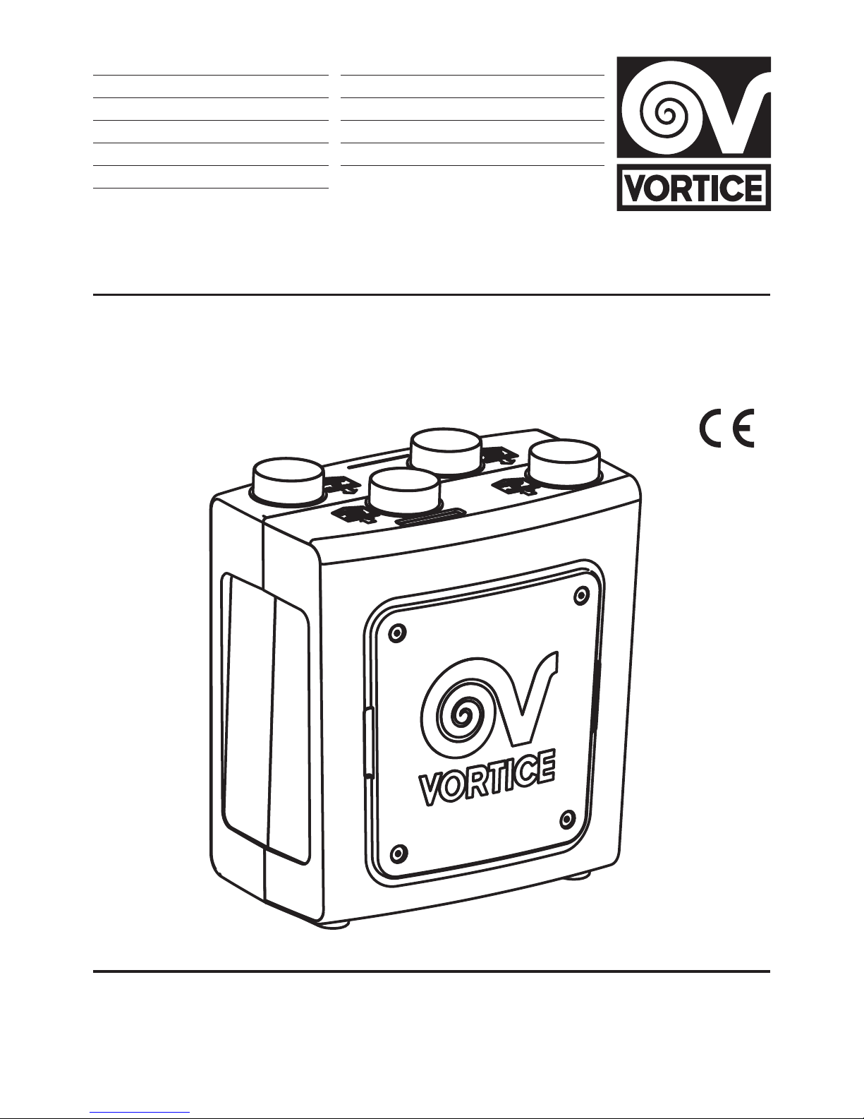
• ATTENTION: to be truly “UK APPENDIX Q” eligible, the
cap supplied with the appliance should be inserted into
the de-frost protection valve inlet, as shown in g.2.
Accessories Supplied
The appliance supplied accessories include:
• a condensation drain pipe;
• a pipette for the connection of the drain pipe;
• 2 lters with F5 level particle retention;
• A silencer, with a standard diameter of 150 mm and
0.5 m in length, to be placed downstream of the
product, on the room intake ducts;
• two metal brackets, on which to mount the apparatus
in a vertical position;
• a radiofrequency (RF) remote control for the initial set
up and subsequent operation of the appliance;
• four supports for horizontal installation of the
appliance.
Installation
The appliance must be installed according to the safety
regulations currently in force in the country of
installation, and the instructions provided by this
manual.
Prerequisites
The appliance must be installed on an internal surface or
wall of the home structurally suited to holding its weight
(at least 200 kg/m2).
The appliance must not be installed in areas where the
temperature may drop below 0°C.
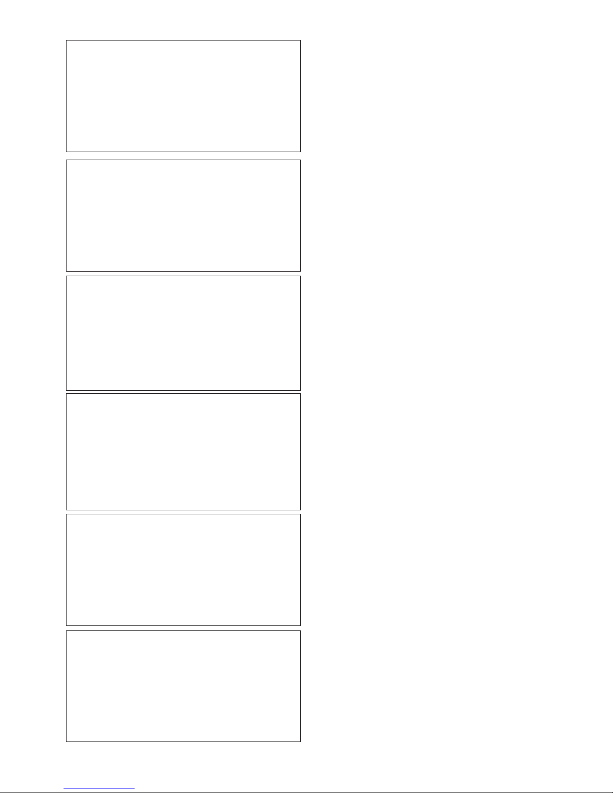
The site chosen for installation must take into account
the position of the power supply cable (1.5.m long) and
the electrical connections that come out of the
underside of the appliance (Fig. 3).
The air distribution ducts must be of the correct size.
The ducts to and from the exterior must be thermally
insulated and not subject to vibrations. The inlet and
outlet ducts, of a standard diameter of 150 mm, must be
secured to the corresponding spigots of the appliance
by means of clips or other suitable fastening systems.
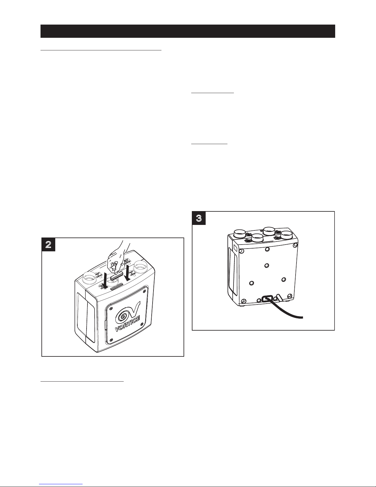
In order to optimize acoustic levels a silencer must be
mounted on the air feed into the home (g.4).
3
2
24
ENGLISH
Page 7
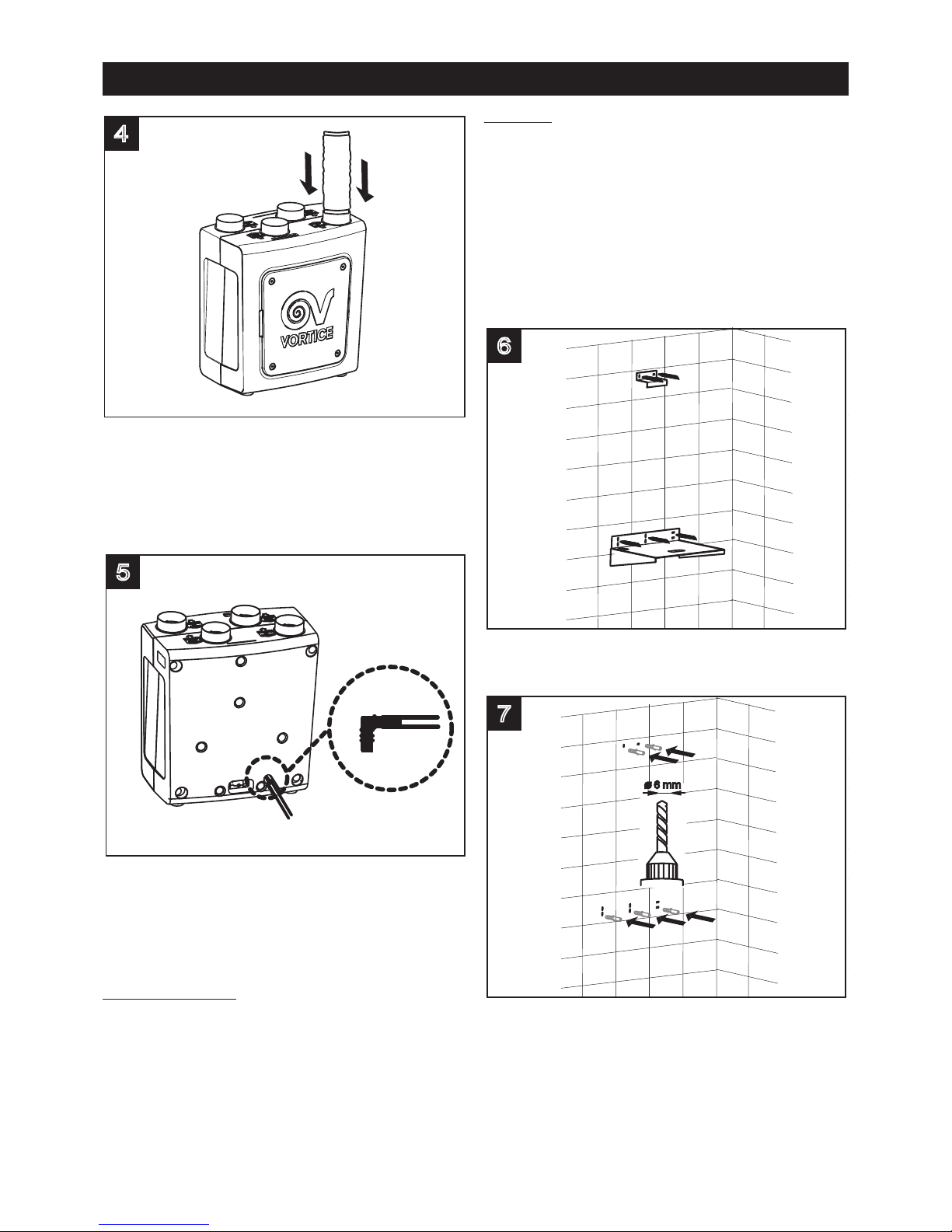
During the course of its normal functioning,
condensation collects on the bottom of the apparatus.
In order to draw it away the small piping provided must
be xed to the attachment on the underside of the
appliance (g.5), and connected to a drainpipe. (for
instructions please see the Assembly paragraph).
The appliance must be easily accessible in case of
servicing/maintenance. In particular a free space of at
least 50 cm must be left in front of the front panel, to
facilitate cleaning and replacement of the heat
exchanger and lters.
Checks on delivery
Check the appliance on delivery, to detect any faults
before proceeding with installation. More specically:
before removing it from the packaging, make sure that
the name and description shown on the box are correct;
when the appliance has been removed from the
packaging, check that there is no visible damage then
make sure that the condensate discharge pipe is
present along with the instruction manual.
Assembly
The appliance comes equipped with two metal brackets
for vertical wall mounting and 4 supports for horizontal
positioning. The equipment required for the fastening of
the brackets is however not provided.
Establish the exact position where the apparatus is to
be located, bearing in mind the installation
requirements.
Vertical mounting on brackets
Fix the brackets to the wall, using appropriate wall
anchors (g.6,7,8).
7
6
5
4
25
ENGLISH
Page 8
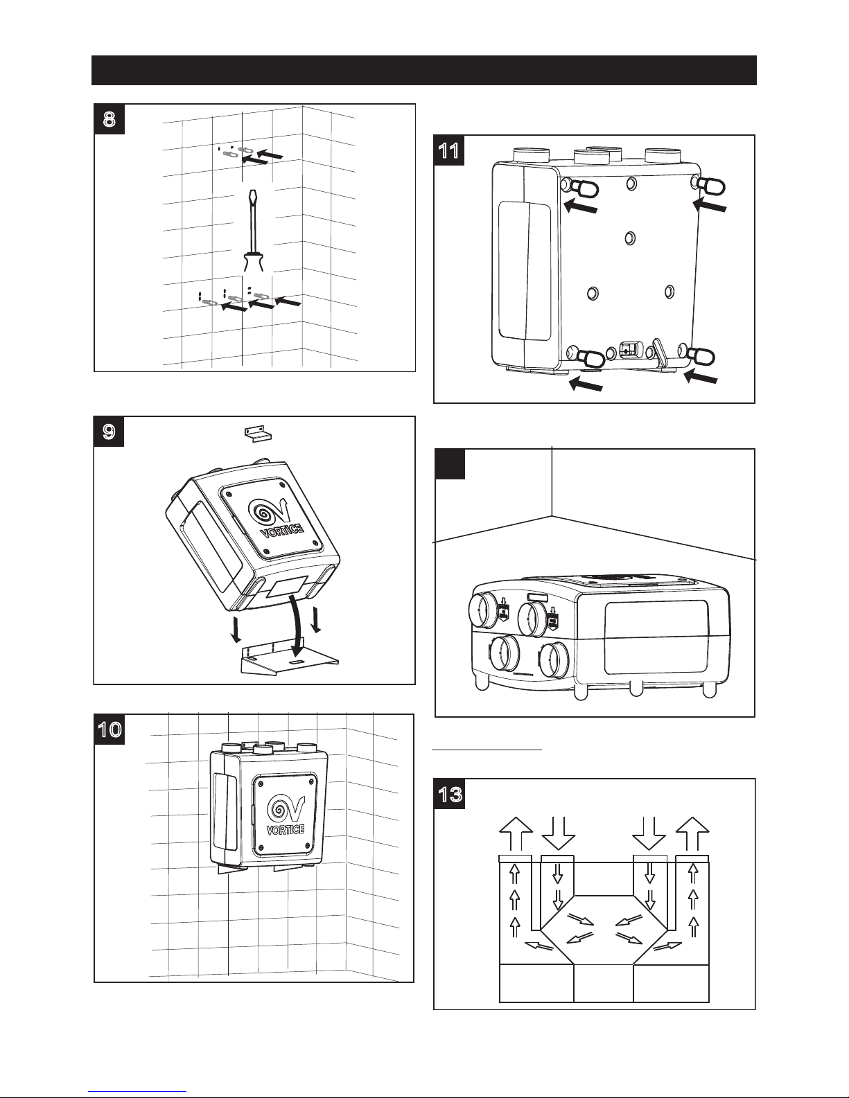
Mount the apparatus on the brackets (g.9,10)
Horizontal assembly on supports
Fix the supports to the appliance (g.11).
Position the appliance on the location surface (g.12).
Duct connections
(g.13)
13
EXTRACT
TO
EXTERNAL
SUPPLY
FROM
EXSTERNAL
EXTRACT
FROM
INTERNAL
SUPPLY
TO
INTERNAL
12
11
10
9
8
26
ENGLISH
Page 9
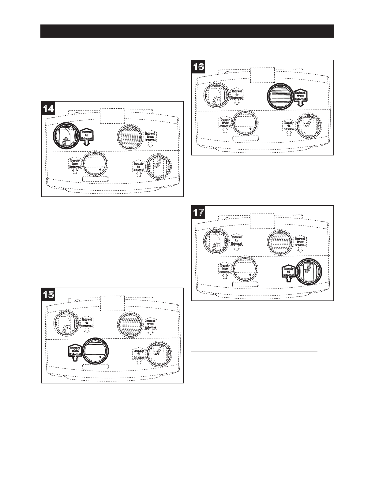
The appliance’s connecting spigots have a standard
diameter of 150 mm . Rigid or exible ducts may be
connected to these inlet and outlet spigots. Each
connection is labelled to specify the direction of the air
ow, as per the following gures.
Stale air flow towards the outside (extract to
external) (g.14)
This outlet is used to expel the stale air outside once it
has been processed by the heat exchanger. The duct to
which the outlet is to be connected must be thermally
insulated (to avoid the formation of condensate on its
inside and outside parts), and equipped with devices to
dampen any vibration. If the terminal is on a roof it is
mandatory to use a suitable device designed to avoid
the formation of condensation and rain water
inltrations.
Fresh air intake from the outside (supply from
external) (g.15)
This inlet is used to supply the air from outside; the duct
must be thermally insulated and provided with devices
capable of dampening any vibration. If the terminal is on
a roof it is mandatory to use a suitable device designed
to avoid the formation of condensation and rain water
inltrations.
Stale air flow extractor from the home (extract from
internal) (g.16)
This inlet is used to introduce the air extracted from
within the house into the appliance. The duct requires
thermal insulation.
Clear air inlet into the home
(supply to internal) (g.17)
This outlet is used to introduce external air into the
home, following treatment in the heat exchanger. In
order to guarantee the optimum level of acoustic
comfort, the silencer provided must be xed to this
outlet.
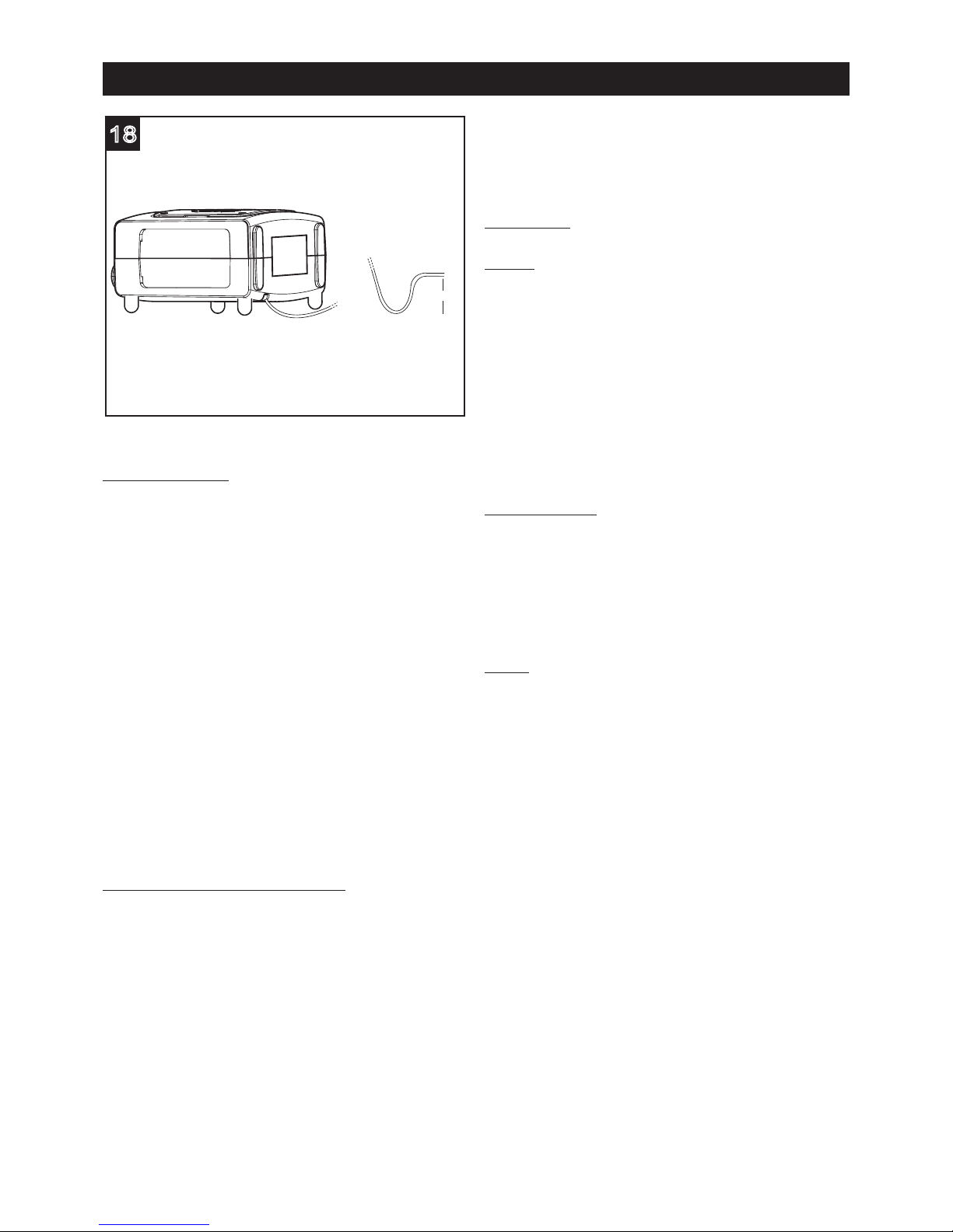
Connection of the condensation draining tube
The connection point for this tube is located on the
underside of the appliance. The condensation drainage
can be achieved by connecting a exible tube, supplied
with the appliance, with an internal diameter of
approximately 19 mm. To avoid the formation of air
locks a siphon must be created with the tube, as shown
in the g.18. Cut the tube end diagonally.
The condensation drainage can also be routed to the
home drainage system.
17
16
15
14
27
ENGLISH
Page 10
Initial setting
To satisfy REGULATORY obligations in force in the
country in which the appliance is installed, the installer
must set the Vmin and Vmax values (Vmed, which can
be selected in MAN mode, will follow on from the Vmin
and Vmax values) during installation, on the basis of the
system specications (length and type of pipes, number
of bends, etc.).
These settings can be implemented by the installer
during the initial startup stage, using the remote control
provided. As well as the speed settings, the initial
conguration also includes adjustment of the air intake
and outlet grilles to and from the rooms.
The initial factory set values for the CO2 and RH
parameter thresholds are OFF and 90%.
In this situation, the appliance does not cut in at all, in
any way.
During this initial conguration process, the installer
should set the values for these thresholds to ensure that
the appliance cuts in as described below.
Appliance/remote control coupling
Before using the remote control, it must be initialised.
This activity should be entrusted to the installer (for
remote controls sold separately), or carried out during
production (for remote controls sold with the appliance).
The procedure is as follows:
a- shut off power for at least 30 sec;
b- restore power;
c- carry out the procedure below within 60 sec.
While the remote control is off, press and hold the
ENTER key for at least 3 seconds: the appliance will
synchronise with the remote control. The remote control
will emit a short but continuous sound signal to conrm
that it has synchronised with the appliance.
When each remote control has been synchronised, the
operational settings implemented up to that point will
automatically be transferred from the remote to the
appliance.
NOTE The complete procedure is described on the
remote control instruction booklet.
Function
Motors
The appliance is equipped with:
Two brushless three phase motors, specically
designed to guarantee very low energy consumption
thanks to their high efciency, which drive two
centrifugal fans with reverse blades provided with high
air ow efciency which respectively extract the stale
and damp air from the service rooms (kitchens,
bathrooms, washrooms, etc), and introduce fresh
external air into the living rooms (sitting rooms, dining
rooms, bedrooms, etc).
A stepper motor, which operates the by-pass and defrosting valves.
Heat Exchanger
The two air ows, the intake and extract, meet in the
appliance, (without ever actually coming into direct
contact, in order not to jeopardize the quality of the
incoming air), inside the heat exchanger, where the
warm outgoing/extracted air yields its heat to the cold
incoming/infed air, thus minimizing the temperature
variation in the dwelling.
Valves
A valve system performs the summer by-pass and
automatic frost protection functions of the heat
exchanger.
By-pass: the purpose of the bypass is to ventilate the
dwelling without heat transfer. The opening of the bypass valves enables the direct introduction of external
air, without it passing through the exchanger. The ow of
air extracted from the house continues to pass through
the exchanger.
In the appliance the by-pass valve opening can take
place in two ways:
Manual, by pressing the MODE / SUMMER button on
the remote control;
Automatic, when the appliance operates in AUTO
mode. In this second case, the valve opens by way of
T
ext
> 15°C if one of the following conditions applies:
• if T
int
> T
set
: T
ext
≤ T
int
or
• if T
int
≤ T
set
: T
ext
> T
int
(T
set
= temperature previously set using the remote
control)
The by-pass valve closes automatically in the other
cases.
Frost protection: The appliance is tted with an
automatic valve system that allows cold air from outside
to mix with warm air in the room where the unit is
installed.
18
60 mm
28
ENGLISH
Page 11

The combined action of this valve and the automatic
adjustment of the airows extracted from and entering
the rooms prevents the formation of frost on the heat
exchanger; this device consists of a valve which allows
the incoming cold air to mix with the warmer air from the
room in which the appliance is installed.
The frost protection procedure on the appliance works
as follows:
the valve begins to open automatically; at the same
time, the air intake fan increases in speed so as to
increase airow.
If this action is insufcient, the outside air intake fan
speed is reduced, to mimimise the amount of heat
needed to heat it up.
If even this action is insufcient, the extractor fan for the
warm air from inside increases its speed, to increase the
heat contribution available, while the intake fan remains
at minimum speed.
Lastly, if even this measure should be insufcient when
faced with particularly bad external climate conditions,
in the absence of an optional heating element, the air
intake fan stops completely and the valve is closed,
while the stale air extractor fan continues operating.
After a certain period of time, the air intake fan starts
again at minimum speed, the valve re-opens and the
external conditions are checked again; if in the
meantime the temperature exceeds the threshold limit,
the actions described above take place in reverse order.
If atmospheric conditions in the room are beyond the
potential of the above-mentioned system, the (optional)
heating element situated upstream of the heat recovery
unit in the fresh air duct automatically cuts in for the
precise time dictated by the appliance and thus ensures
that the aim is achieved.
N.B.
The frost protection switching on prevents any change
to the status of the appliance. Any commands made will
not be carried out by the appliance, and the message
“DEF” will be displayed temporarily.
This will remain on the screen for a few seconds and will
then disappear and reappear every 15 minutes for as
long as the heating element is powered by automatic
data updates from the appliance to the remote control.
If a malfunction is detected in the heater, the word “ICE”
will ash on the remote control display and will be
followed by a single beep. Carry out the RESET
procedure. The heating element icon will continue to
ash, to indicate the heater fault. In this case, contact
the Technical Support Centre.
IMPORTANT: make sure that nothing is placed close to
the anti-frost valve, as this could obstruct its normal
operation.
Filters
Two F5 lters, placed inside the inlet and extraction
channels close to the heat exchanger and accessible by
removing the front panel, safeguard it from the
impurities contained in the extracted stale air and avoid
the introduction of polluted air into the dwelling served
by the system.
A further optional lter, of class F7, placed in the internal
duct after the F5 lter, can provide an additional ltering
capability.
The state of lter clogging is constantly monitored by
the system, completely automatically. The need for
maintenance/replacement is signalled, both visually and
acoustically, on the remote control.
Sensors
The appliance is equipped with three temperature
sensors, one relative humidity sensor, which integrates a
further temperature sensor, and a CO2sensor. More
specically, if the relative humidity, CO
2
and
temperature sensors detect values above the threshold
levels, the appliance operation adapts automatically, to
restore normal environmental conditions or at least in
line with those set.
IMPORTANT
Before the appliance will work correctly, the CO2/RH(%)
sensor needs an average of 1 hour for auto-calibration
purposes.
29
ENGLISH
Page 12
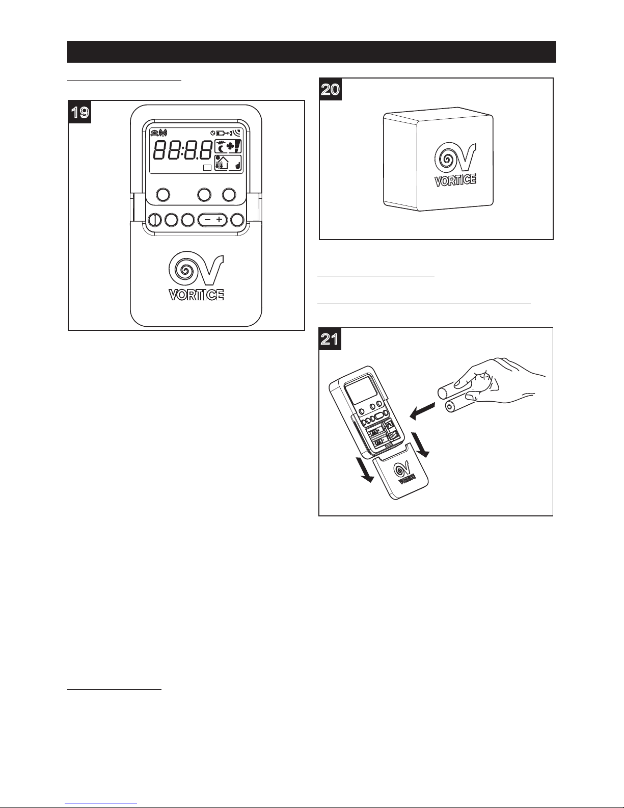
Remote control provided
(g.19)
All the functions of the appliance are managed through
the radiofrequency (RF) remote control. The functions
assigned to the various keys are the following:
(To see their use check the “Instruction for use”
paragraph):
• setting the initial values of Minimum and Maximum
Speed (to be performed by the Installer);
• enable/disable further variations to minimum and
maximum speed settings (for installer only).
• setting the mode of operation: Manual, Summer, Auto;
• setting the appliance operating speed, in the Manual
Mode;
• setting temperature limits, relative humidity and CO
2
concentration in served premises.
• enabling and disabling (to be performed by the
Installer) the operating options available, by
introducing a pre-established and un-changeable
sequence of keys, that will force the appliance to
operate, continuously, in the AUTO mode; the user
can only set the TIMER function and change the time
or day of the week;
• setting the TIMER;
• display of the temperature, relative humidity and CO
2
concentration values in the served dwelling
• display of the time and date;
• display of the clogged state of the lters (a condition
highlighted by an acoustic warning);
• display of the code for any appliance malfunction.
Additional RF device
An additional radiofrequency (RF) device, including a
connection cable is available as an option, and allows
the control of the apparatus even if the position chosen
for its installation is screened from radio waves.
(g.20)
Instruction for use
Instructions on how to use the remote control:
Insert the batteries (g.21);
21
20
DISPLAY TIMER MODE
SET NEXT ENTER
19
CO2(ppm) RH(%)
Mo Tu We Th Fr Sa Su
AUTO
BP
°C
F
30
ENGLISH
Page 13

ON/OFF button (g.22)
Enables the appliance to be turned on and off. The
command is performed only if the button is pressed for
at least 0.5 seconds. With the appliance off the time and
day of the week are displayed. This function may be
disabled. On turning the appliance on the AUTO mode
is activated at a speed of V
min
.
SET button (g.23)
Sets the following parameters. To move from one
parameter/eld to the next, press NEXT.
Time/day setting (g.23a):
• press SET to view the parameter;
• set the value of the flashing field with the + and - keys;
the sequence will be: HOURS, MINUTES, DAY.
Temperature setting (g.23b)
:
• to view the parameter, press: SET and NEXT (several
times);
• set the value of the flashing field with the + and - keys;
the sequence will be: C/F (unit of measurement, °C for
degrees Celsius, F for degrees Fahrenheit), internal T
value (from 15°C to 30°C, in steps of 1°C).
Relative humidity setting (g.23c)
:
• to view the parameter, press: SET and NEXT (several
times);
• set the value of the flashing field with the + and - keys
(from 40% to 90%, in steps of 5%).
RH(%)
23c
23b
°C
23a
23
DISPLAY TIMER MODE
SET
NEXT ENTER
Su
AUTO
22
DISPLAY
TIMER MODE
SET NEXT ENTER
Su
AUTO
31
ENGLISH
Page 14

Maximum CO2concentration setting (ppm) (Fig. 23d):
• to view the parameter, press: SET and NEXT (several
times);
• set the value of the flashing field with the + and - keys
(from 500 ppm to 3000 ppm, in steps of 50 ppm, or
OFF: no CO2monitoring).
Speed V
min
setting (g.23e):
V
min
setting (g.23e):
• to view the parameter, press: SET and NEXT (several
times);
• set the value of the flashing field with the + and - keys
(from 0 to 69, in steps of 1).
Speed V
max
setting (g.23f):
• to view the parameter, press: SET and NEXT (several
times);
• set the value of the flashing field with the + and - keys
(from Vmin+10 to 99, in steps of 1).
DISPLAY button (g.24)
During normal operation, the following information will
appear on the remote control display when the
appliance is switched on:
the time;
the day of the week;
the operating mode: (AUTO, MAN, BP);
the operating speed: (Min, Max, Mid (the latter in MAN
mode only)).
Press and hold the DISPLAY key for half a second
repeatedly to view the following system parameters in
sequence:
outdoor temperature (g.24a)
during normal operation, detected by the temperature
sensor located in the house outlet duct, before the heat
exchanger;
24a
°C
24
DISPLAY
TIMER MODE
SET NEXT ENTER
Su
AUTO
23f
23e
CO2(ppm)
23d
32
ENGLISH
Page 15

indoor temperature (g.24b)
during normal operation, detected by the temperature
sensor located in the intake duct, coming from the
rooms served, before the heat exchanger;
Current humidity display (g.24c)
(detected by the sensor located in the house outlet duct,
before the heat exchanger);
CO
2
percentage display (g.24d)
(detected by the CO2sensor placed in the home air inlet
shaft, before the heat exchanger).
Residual operating time at Vmax
,(g.24e)
depending on preset Timer duration (see TIMER button)
Other information displayed automatically, depending
on the conditions:
Excess CO
2
threshold warning (see “Warning/error
signals")
Value set during initial conguration of Min and Max
Speed (values from 00 to 69, 10 to 99: only during the
installer set up stage)
Clockface symbol
: if the Timer function is set (see
“TIMER button”)
Clogged lters
(see “Warning/error signals”)
Battery charge low (see “Warning/error signals”)
System malfunction
(see “Warning/error signals”
TIMER button (g.25)
It forces the device to operate at Max Speed for 10 min
(press key for 0.5 sec), 20 min (press twice), 30 min
(press three times), or continuosly (press four times).
Pressing the key for a fth time (OFF) restores operation
at the previously set speed, unless over-ridden by the
sensors.
25
DISPLAY
TIMER
MODE
SET NEXT ENTER
Su
AUTO
24e
CO2(ppm)
24d
RH(%)
24c
24b
°C
33
ENGLISH
Page 16

The display will also show (g.25a):
• The TIMER icon;
• The duration set (10,20,30,CO;
If the programming time has elapsed (or if you press the
TIMER key ve times repeatedly until OFF), the
appliance will go back to the previously set function
mode.
MODE button (g.26)
Used to select one of the available operating modes
(MAN, BP, AUTO). Press the key to switch between
modes.
AUTO (g.26a)
:
the operating speed is automatically set by the system,
depending on the environmental conditions detected by
the sensors; if necessary the by-pass and frost
protection valves are activated automatically;
Bypass function activation is indicated by the ashing
"BP" icon on the display.
MAN (g.26b)
:
the operating speed is decided by the user (the CO
2
and relative humidity sensors can still trigger a shift to
Max speed if necessary);
BP (g.26c):
this forces the opening of the by-pass valve, irrespective
of the actual desired internal, desired or external
temperature values.
The shift from one operating mode to the other is
achieved by pressing the MODE button for at least 0.5
seconds
NEXT, - +, ENTER buttons (g.27)
Already described in other parts of this document.
27
DISPLAY
TIMER
MODE
SET NEXT ENTER
Su
AUTO
Su
26c
BP
Su
26b
Su
26a
AUTO
26
DISPLAY
TIMER
MODE
SET NEXT ENTER
Su
AUTO
25a
34
ENGLISH
Page 17

Adjusting motors individually (to be performed by the
installer) (g. 28a, 28b, 28c, 28d)
Use the following key sequence:
DISPLAY --> SET --> DISPLAY --> TIMER
to enable the option of setting the revs at minimum
speed and maximum speed for each motor (delivery and
extraction);
• set the value of the ashing eld with the + and - keys
(from 0 to 69, in steps of 1);
• press NEXT to move on to the next parameter; the
sequence will be: delivery motor minimum speed L1,
delivery motor maximum speed H1, extraction motor
minimum speed L2, extraction motor maximum speed
H2.
Repeat the key sequence to return to the simultaneous
control of both motors.
Disabling certain commands
(by the Installer)
To satisfy the requirements of some specic application
certain functions accessible through the remote control
may be disabled by the installer. In this case the
appliance will operate in AUTO mode only: the user
can only set the TIMER function and change the time or
day of the week using the SET button to set the TIMER
and display:
the actual temperature of the stail air, before the heat
exchanger;
the relative humidity percentage of the stail air, before
the heat exchanger;
the CO2concentration of the stail air, before the heat
exchanger;
the TIMER setting.
Pressing the other buttons, will be considered an
accidental event and will cause any action.
Prevention of changes to V
min
and V
max
speed
The installer can prevent others from making changes to
the maximum and minimum speed settings once he has
made the initial settings.
Warning/error signals
• When the CO2 limit is exceeded, an alarm condition is
generated which lights up the CO2 symbol on the
remote control. The appliance starts running at
maximum speed until the concentration of CO2 drops
below the limit value.
• When the batteries are exhausted, an icon
ashes on the remote control unit accompanied by a
sound signal (series of double beeps). When the
batteries are replaced, the sound signal stops and the
icon switches off.
• The dirty lters condition is indicated by a sound
signal (a series of beeps lasting 5 seconds) and the
corresponding icon will ash on the display. This
signal stops when lter cleaning takes place.
• The clogged lters condition is indicated by a sound
signal (a series of beeps lasting 5 seconds) and the
corresponding icon will ash on the display. In this
situation, the appliance automatically stops the
motors and opens the by-pass valve, to guarantee a
minimal air exchange. This signal stops when lter
cleaning takes place.
Malfunctions are indicated by error codes (ER01, ER02,
28d
28c
28b
28a
35
ENGLISH
Page 18

etc...) on the display and by a series of double beeps.
These warnings persist until normal appliance operating
conditions have been restored. Malfunctions will be
indicated as follows:
ER01: by-pass/de-frosting valve blocked
ER02: motor driving outside air intake fan blocked
ER03: motor driving stale air exhaust fan blocked
ER04: remote control not receiving signals from
appliance
ER05: replace the lters
ER06: temperature sensor in the outdoor fresh air intake
duct, upstream of the exchanger, not active
ER07: temperature sensor in the outdoor fresh air intake
duct, downstream of the exchanger, not active
ER08: temperature sensor in the stale air outlet duct
leaving the household, downstream of the exchanger,
not active
ER09: Relative Humidity sensor in the stale air outlet
duct leaving the household, upstream of the exchanger,
not active
ER10: CO2sensor in the stale air outlet duct leaving the
household, upstream of the exchanger, not active
ER12: outdoor temperature higher than the limit value
ER14: indoor temperature higher than the limit value.
N.B.
It should be noted that error signals (ER01, ER02 and
ER03, ER12, ER14 codes) caused by critical appliance
malfunctions will cause the appliance to stop working
until the problem has been resolved. In this case, the
beep will sound for 30 seconds; after this time it will
stop and an error message will remain on the display. In
other cases, once a problem has been signalled, the
appliance continues to run in the mode set previously.
The beep will sound for 5 seconds; after this time it will
stop and an error message will remain on the display.
Under these circumstances, the user will not be able to
change the operating mode (e.g. MAN or BP).
Reset error code
To stop the error code from being displayed (if the
remote control has not been disabled) press the
following keys one after the other: DISPLAY --> “-” -->
DISPLAY --> “+”.
After the RESET, the appliance starts running in AUTO
mode, in line with the standard initial parameters, only if
the problem causing the error has been resolved.
Similarly, if the appliance power supply has been cut off,
when it is restored the appliance will resume operation
in AUTO mode, in accordance with the standard initial
parameters.
Fuse
The appliance has 2 A fuse tted in series with the
power supply cable. (g.29)
In the event of repeated fuse failures, the appliance
should be checked by a trained electrician.
Maintenance/Cleaning
Filters
The periodical cleaning and maintenance of the lters is
left to the user. The lters must be kept clean to ensure
a correct and healthy operation of the appliance.
It is advisable to replace the lters once a year. To
access the lters follow the instructions below:
switch off the appliance (ON/OFF button);
wait 15 seconds;
disconnect the appliance from the mains power
supply;
extract the filters from the appliance (g.30,31,32);
30
29
36
ENGLISH
Page 19

clean the filters using a vacuum cleaner; it is preferable
to replace the lters after a few cleanings and in any
case at least once a year;
reinstall the filters (g.33,34,35);
In case of prolonged inactivity of the appliance we
recommend removing the lters, to prevent the risk of
being damaged, due to the possible formation of
condensation.
Heat exchanger
The heat exchanger does not usually require regular
cleaning. The frequency of cleaning is determined by
the level of air pollution (in input and output from the
home) and the state of efciency of the lters.
The heat exchanger should in any case be replaced
every 6 years, even if the lters have been subjected to
regular maintenance.
To access the exchanger follow the instructions below:
disconnect the appliance from the mains power
supply;
35
34
33
32
31
37
ENGLISH
Page 20

extract the exchanger (g.36,37,38)
clean the exchanger;
reinstall the exchanger (g.39,40,41)
41
40
39
38
37
36
38
ENGLISH
Page 21

Replacement of the remote control batteries
open the battery compartment cover (fig.42);
insert 2 AA type batteries ensuring that the polarities
shown on the bottom of the compartment are complied
with; replace the battery compartment cover.
Important information concerning
the environmentally compatible
disposal
IN CERTAIN EUROPEAN UNION COUNTRIES THIS
PRODUCT DOES NOT FALL WITHIN THE
REQUIREMENTS OF THE NATIONAL LAWS
IMPLEMENTING DIRECTIVE WEEE, AND IN THESE
COUNTRIES THE PRODUCT IS NOT SUBJECT TO
SEPARATE DISPOSAL OPERATIONS AT THE END OF
ITS WORKING LIFE.
This product conforms to EU Directive2002/96/EC.
This appliance bears the symbol of the
barred waste bin. This indicates that, at
the end of its useful life, it must not be
disposed of as domestic waste, but must
be taken to a collection centre for waste
electrical and electronic equipment, or returned to a
retailer on purchase of a replacement.
It is the user's responsibility to dispose of this appliance
through the appropriate channels at the end of its useful
life. Failure to do so may incur the penalties established
by laws governing waste disposal.
Proper differential collection, and the subsequent
recycling, processing and environmentally compatible
disposal of waste equipment avoids unnecessary
damage to the environment and possible related
healthrisks, and also promotes recycling of the materials
used in the appliance.
For further information on waste collection and disposal,
contact your local waste disposal service, or the shop
from which you purchased the appliance.
Manufacturers and importers fulfil their responsibilities
for recycling, processing and environmentally
compatible disposal either directly or by participating in
collective systems.
42
BATTERIES
NOT
INCLUDED
39
ENGLISH
Page 22

40
ENGLISH
Table 1.1 A
Room Minimum intermittent extract rate Continuous rate
Minimum high rate Minimum low rate
Kitchen 30 l/s (adjacent to hob); Total extract rate
or 60 l/s elsewhere 13 l/s must be at least
Utility room 30 l/s 8 l/s
the whole building
Bathroom 15 l/s 8 l/s
ventilation rate in
Sanitary Accomodation 6 l/s
Table 1.1B
Table 1.1 B
Number of bedrooms in dwelling
1 2 3 4 5
Whole building ventilation rate (l/s) 13 17 21 25 29
Minimum value in any dwelling of 0,3 l/s per m
2
oor area
BUILDING REGULATIONS DOCUMENT F1 2006
CONTINUOUS MECHANICALSUPPLY & EXTRACT
VENTILATION WITH HEAT RECOVERY
A continuous balanced mechanical central supply and extract system to
be positioned in loft or cupboard space. An integral heat exchanger
recovers a large percentage of heat energy that would have otherwise
been lost. In employing this type of system, there is no need to install
background ventilators in the dwelling.
CONTINUOUS SUPPLY AND EXTRACT
1 Determine the whole building ventilation rate from Table 1.1B
Allow for inltration by subtracting
- for multi storey dwellings: 0.04 x gross internal volume of dwelling
heated space (m
3
)
- for single storey dwellings: 0.06 x gross internal volume of dwelling
heated space (m
3
)
2 Calculate the whole dwelling extract rate at maximum operation by
adding the individual room rates for ‘minimum high rate’ from Table 1.1A
3 The required air ow rates as as follows:
Maximum Extract Rate (boost) is the greater step of 1 and 2 above.
The Minimum individual room extract rates sholuld be at least those
given in Table 1.1A for minimum high rate
Minimum air supply rate should be at least the whole building
ventilation rate in 1 above.
4 No Background ventilators are required with System 4
In addition, the minimum ventilation rate should not be less than 0.3 l/s per m2internal oor area (this includes each oor, e.g.
for a two-storey building, add the ground and rst oor areas).
This is based on two occupants in the main bedroom and a single occupant in all other bedrooms. This should be used as the
default value. If a greater level of occupance is expected, then add 4 l/s per occupant.
SYSTEM 4
BATHR OOM
BED ROO M
HEAT REC OVE RY
UNI T
KIT CHE N
LIV ING
ROO M
Page 23

Overensstemmelse med
bygningsreglementet
Den nyeste lovgivning angående begrænsningen af
energiforbruget medfører krav om overholdelse af en
række betingelser til ydelsen fra og energiforbruget ved
ventilationsapparater.
I særdeleshed kræves det i 2006-udgaven af det britiske
bygningsreglement “UK Building Regulations Document
F1”, i afsnittet “System 4 Continuos mechanical extract
with heat recovery (MVHR)”, at der sikres en
minimumværdi for den maksimale kapacitet i hvert
“vådrum” (for køkkener 13 l/s, for vaskerum og baderum
8 l/s, for toiletrum 6 l/s).
Den garanterede mindsteværdi for minimumkapaciteten
beregnes derimod ud fra antallet af soveværelser i
boligen ved at sammenlægge kapaciteten (udtrykt i l/s),
som ndes i tabellen “1.1b”. Den samlede kapacitet fra
den beregning må ikke ligge under 0,3 l/s pr. m2 af det
samlede boligareal (hvor alle etager tælles med). Til den
værdi, som er anvendt i hypotesen med 2 beboere i det
første soveværelse og 1 i hvert af de efterfølgende, skal
der tillægges yderligere 4 l/s for hver ekstra beboer i
soveværelserne, samt endnu en faktor til kompensation
for tab og indtrængen af luft.
Beskrivelse og brug
VORT PROMETEO PLUS HR 400 (herefter kaldet
“apparatet”) er et centraliseret og meget effektivt
ventilationssystem med genindvinding af varme. Det
kan monteres vandret (med de medfølgende
understøtninger) og lodret (på gulvet eller på væggen
med de metalholdere, apparatet er forsynet med).
Ved normal drift udsuges den tunge, dårlige luft fra
køkkenet, baderum, vaskerum og spisekamre. Samtidig
ledes frisk luft udefra ind i soveværelser og forskellige
opholdsrum. Værdierne for den nødvendige
luftkapacitet kan ndes i gældende national lov. I
Storbritannien gælder: UK “Building Regulations
Document F1”.
Ved normal drift er der stort set overensstemmelse
mellem de samlede voluminer af udsuget og indsuget
luft. Luftind- og udtagene er helt separate og passende
ltrerede. I vinterhalvåret yttes varmen fra luftudtaget til
luftindtaget med ca. 95% effektivitet. Den kondens, der
opstår i processen, og som opsamles indvendigt i
apparatet, skal derefter ledes ud i det fri.
Apparatet sikrer en støjsvag og effektiv
ventilation/udsugning af luft fra huset, hvor den “dårlige”
luft fjernes fra alle vådrum, og der skabes en permanent
luftstrøm via apparatet gennem alle boligens tørre rum.
Luften ledes via apparatet ind i en effektiv varmeveksler,
hvor varmen fra den udsugede luft overføres til den
friske luft i indsugningen, før den ledes ud i boligens
rum.
Temperaturintervaller
Temperaturintervallet for ekstern luft (det er
temperaturen på den friske luft, der suges ind i boligen
inden varmeveksleren og dermed uopvarmet)
kompatibelt med korrekt funktion af apparatet ligger
mellem - 30°C og + 50°C (temperaturer < - 30°C vises
med ikonet for det eksterne termometer, der blinker på
fjernbetjeningen. Temperaturer > +50°C vises med et
fejlsignal, og i så fald standser apparatet).
Temperaturintervallet for intern luft (det er temperaturen
på den luft, der suges ud af boligen inden
varmeveksleren og dermed uafkølet) kompatibelt med
korrekt funktion af apparatet ligger mellem + 10°C og +
50°C (ved interne temperaturer over denne værdi
standser apparatet og udsender en fejlkode).
Garanti og ansvar
Garanti
Garantien på apparatet gælder i 2 år fra købsdatoen.
Garantien dækker ikke:
Omkostninger til montering/afmontering.
Skader, der efter Vortice Elettrosocialis skøn skyldes
ukorrekt eller uagtsom brug af apparatet.
Skader, der skyldes reparationer eller forsøg på
reparationer foretaget af tredjemand uden autorisation
fra Vortice.
Ansvar
Apparatet er fremstillet til “balancerede
ventilationssystemer”. Enhver anden brug, der ikke på
forhånd er diskuteret med en ekspert fra Vortice, kan
blive regnet som ukorrekt. I så fald kan Vortice ikke
holdes ansvarlig for eventuelle fejl eller defekter.
Vortice påtager sig ikke ansvaret for fejl grundet:
Ukorrekt brug af apparatet.
Normalt slid på apparatet.
Manglende overholdelse fra brugerens side af
anvisningerne i brugervejledningen.
96
DANSK
Page 24

• Følg sikkerhedsanvisningerne for at undgå skader
på brugeren.
• Brug ikke apparatet til andet, end hvad er angivet i
disse anvisninger.
• Efter at have fjernet emballagen fra produktet, skal det
kontrolleres, at det er uden synlige skader: I tilfælde af
tvivl skal man straks kontakte en faguddannet tekniker
eller et Vortice-servicecenter.
• Efterlad ikke dele af emballagen inden for børns og
funktionshæmmedes rækkevidde.
• Brugen af ethvert elektrisk apparat gør det nødvendigt
at overholde visse grundlæggende regler, her i blandt:
Rør ikke ved apparatet med våde eller fugtige hænder.
Rør aldrig apparatet barfodet.
• Dette apparat er ikke beregnet til at blive brugt af
personer (herunder børn), der er fysisk, sensorisk eller
mentalt funktionshæmmede, eller som ikke har
erfaring med eller viden om apparatet, medmindre de
overvåges eller oplæres i brugen af apparatet af en
person med ansvar for deres sikkerhed. Børn skal
overvåges for at sikre, at de ikke leger med apparatet.
• Brug ikke apparatet i nærheden af brandfarlige stoffer
eller dampe såsom alkohol, insektdræbende midler,
benzin og lignende.
• Anbring apparatet uden for børns og
funktionshæmmedes rækkevidde, når det frakobles
strømforsyningen og ikke længere skal bruges.
• Foretag ikke nogen form for ændringer på apparatet.
• Anvisningerne på vedligeholdelse skal følges for at
forhindre skader og/eller unødigt slid på apparatet.
• Udsæt ikke apparatet for vind og vejr (regn, sol osv.).
• Anbring ikke genstande på apparatet.
• Den indvendige rengøring af apparatet må kun udføres
af sagkyndigt personale.
• Kontrollér regelmæssigt apparatets tilstand. Hvis der
findes defekter, må apparatet ikke bruges, og der skal
rettes henvendelse til et autoriseret Vortice
servicecenter.
• I tilfælde af funktionsfejl og/eller defekter, skal der
straks rettes henvendelse til et autoriseret Vortice
servicecenter. Bed altid om originale reservedele fra
Vortice, hvis apparatet skal repareres.
• Hvis ledningen eller stikket bliver beskadiget skal de
udskiftes så hurtigt som muligt. Dette skal ske på et
autoriseret Vortice kundecenter.
• Hvis apparatet falder ned eller bliver stødt, skal det
straks kontrolleres på et autoriseret Vortice
servicecenter.
• Installation af apparatet skal udføres af sagkyndigt
personale.
• Apparatet skal være monteret på en måde, der
garanterer, at der ikke under normale driftsbetingelser
kan befinde sig mennesker i nærheden af bevægelige
dele eller dele under spænding.
• I tilfælde af:
afmontering af apparatet med dertil egnet værktøj,
udtagning af varmeveksleren og
udtagning af motorenheden,
skal apparatet afbrydes og kobles fra
strømforsyningen.
• Produktet skal tilsluttes en strømforsyning, som er
udført i overensstemmelse med gældende regler.
• Til installationen skal der anvendes en topolet afbryder
med en kontaktåbning på mindst 3 mm.
• Slut kun apparatet til strømforsyningen/stikkontakten,
hvis spændingen i anlægget/stikkontakten passer til
apparatets maksimale effekt. Hvis det ikke er tilfældet,
skal man straks kontakte faguddannet personale.
• Sluk hovedafbryderen til anlægget, når:
Der registreres en funktionsfejl.
Det besluttes at foretage udvendig vedligeholdelse.
Det besluttes ikke at anvende apparatet i kortere eller
længere perioder.
• Apparatet må ikke bruges til at aktivere vandvarmere,
varmeapparater og lignende, og det må ikke udlede
luft i varmtvandsrør, der er forbundet med disse
apparater.
• Apparatet skal udlede luft i en enkelt rørledning direkte
ud i det fri.
• Den udsugede luft skal være ren (altså uden fedtstoffer,
sod, kemiske og korrosive stoffer eller brændbare og
eksplosive blandinger).
• Apparatets ind- og udsugningsåbninger må aldrig
tildækkes eller tilstoppes, og luften skal altid kunne
strømme frit.
• Forsyningsnettets elektriske specifikationer skal svare
til specifikationerne på typepladen A (fig.1).
A
1
Advarsel:
dette symbol angiver, at det er nødvendigt,
at tage forholdsregler for at undgå at beskadige
apparatet
!
Pas på:
dette symbol angiver, at det er nødvendigt,
at tage forholdsregler for at undgå læsioner af
brugeren
!
97
DANSK
Page 25

Struktur og tilbehør
Apparatet består primært af følgende dele:
• Hylster i to dele, der omfatter
tilslutningsmekanismerne til indsugningsrørene og
danner et vandtæt hylster om de interne dele og
varmeveksleren.
• De interne fremføringsrør, der sørger for fordelingen af
luftowene og maksimerer varmeisoleringen og
minimerer tabene.
• Varmeveksleren af plastmateriale og af typen med
modsatrettet ow, hvis specielle morfologi sikrer en
meget høj effektivitet af termisk udveksling (op til
95%).
• De to motorer, af typen brushless med tre faser og
monteret på antivibrationsbeslag, der aktiverer
svinghjulene.
• Skridtmotoren, der styrer bypassventilen og
frostbeskyttelsesventilen.
• Den elektroniske enhed, der styrer forsyningen,
betjeningen og styringen af apparatet.
• Følerne (temperatur, relativ fugtighed og CO2), på
basis af hvilke systemets elektronik automatisk
bestemmer funktionsmetoden.
Medfølgende tilbehør
Standardtilbehøret til apparatet omfatter:
• Et rør til udledning af kondens.
• Et rør til forbindelse til udledningsrøret.
• 2 ltre med ltergrad F5.
• En lyddæmper med normal diameter på 150 mm og
længde på 0,5 m, der skal anbringes efter produktet
på rørene til rummene.
• To metalholdere til lodret montering af apparatet.
• En fjernbetjening med radiofrekvens (RF) til
startkongurationen samt efterfølgende styring af
apparatet.
• Fire understøtninger til den vandrette montering af
apparatet.
Installation
Apparatet skal installeres i henhold til gældende
sikkerhedsregler i anvendelseslandet samt til
anvisningerne i denne håndbog.
Krav
Apparatet skal monteres på en overade eller på
boligens indre vægge, der er i stand til at bære dets
vægt (bæreevne mindst 200 kg/m2)
Apparatet må ikke monteres i lokaler, hvor temperaturen
kan falde til under 0°C.
I forbindelse med det valgte monteringssted skal der
tages hensyn til placeringen af strømkablet med en
længde på 1,5 m samt til de elektriske tilslutninger, der
ndes nederst på apparatets ene side (g. 2).
Rørene til kanalerne skal have de korrekte mål.
Rørene fra og ud til det fri skal være termisk isolerede og
må ikke udsættes for vibrationer
Ind- og udsugningsrørene med en nominel diameter på
150 mm skal være fastgjort til de tilhørende åbninger på
apparatet med spændebånd eller andre passende
tætlukkende anordninger.
For at opnå en så støjsvag drift som muligt, skal den
medfølgende lyddæmper monteres på røret, der sender
luft ud i boligen (g. 3).
Under normal drift opsamles der kondens på bunden af
apparatet, og derfor er det nødvendigt at montere det
lille medfølgende rør på tilslutningen i bunden af
apparatet (g. 4), så kondensen kan udledes i et aøb
(se Montering vedrørende funktionen).
3
2
98
DANSK
Page 26

Apparatet skal være let tilgængeligt i forbindelse med
service og vedligeholdelse. Især skal man sørge for, at
der er mindst 50 cm fri plads i forbindelse med
frontpanelet, så det er let at foretage rengøring og skift
af varmeveksleren og ltrene.
Kontrol ved leveringen
Kontrollér apparatet ved leveringen for at opdage
eventuelle fejl, inden apparatet installeres. I
særdeleshed:
Det skal kontrolleres, inden apparatet tages ud af
emballagen, om navnet og beskrivelsen på kassen er
korrekte.
Når apparatet er taget ud af emballagen, skal det
kontrolleres, om der er synlige skader, samt om kassen
indeholder det lille rør til udledning af kondensvand og
brugervejledningen.
Montering
Apparatet er forsynet med to metalholdere til lodret
montering på væg samt 4 understøtninger til vandret
montering. Derimod medfølger der ingen
fastgørelsesanordninger til brug for monteringen.
Bestem den nøjagtige placering til apparatet under
hensyntagen til installationskravene.
Lodret montering på holdere
Fastgør holderne til væggen ved hjælp af passende
rawlplugs (g. 5,6,7)
7
6
5
4
99
DANSK
Page 27

Montér apparatet på holderne (g. 8,9).
Vandret montering på understøtninger
Sæt understøtningerne på apparatet (g.10).
Anbring apparatet på den endelige plads (g.11).
Tilslutning af rørene
(g.12)
Apparatets tilslutninger har en nominel indvendig
diameter på 150 mm. Til apparatets åbninger kan der
tilsluttes både stive rør og exslanger. I det følgende er
alle tilslutninger illustreret med en gur, der også
specicerer, hvorfra luftowet kommer og skal sendes
hen.
Udsugning
af dårlig luft
mod det fri
Indsugning
af frisk luft
udefra
Udsugning
af dårlig luft
fra boligen
Tilførsel
af frisk luft
til boligen
11
9
8
100
DANSK
Page 28

Udsugning af dårlig luft mod det fri
(extract to external) (g.13)
Denne åbning anvendes til udsugning til det fri af dårlig
luft, der allerede er blevet behandlet i varmeveksleren.
Det rør, som aøbet skal sluttes til, skal være termisk
isoleret (for at undgå dannelsen af kondens på inder- og
ydersider) og være forsynet med vibrationsdæmpere.
Hvis aøbet sker fra taget, er det obligatorisk at
anvende et passende system til forhindring af dannelsen
af kondens samt indtrængen af regnvand.
Indsugning af frisk luft udefra
(supply from external). (g.14)
Denne åbning anvendes til indsugning af luft fra det fri.
Det tilhørende rør skal være termisk isoleret og være
forsynet med vibrationsdæmpere. Hvis indsugningen
sker fra taget, er det obligatorisk at anvende et
passende system til forhindring af dannelsen af kondens
samt indtrængen af regnvand.
Udsugning af dårlig luft fra boligen
(extract from internal) (g.15)
Denne åbning anvendes til at lede luften fra det indre af
boligen til apparatet. Røret skal være termisk isoleret.
Tilførsel af frisk luft til boligen
(supply to internal) (g.16)
Denne åbning anvendes til tilførsel af frisk luft til boligen,
der allerede er blevet behandlet i varmeveksleren. For at
sikre en så støjsvag drift som muligt, skal den
medfølgende lyddæmper monteres på dette rør.
Tilslutning af udledningsrøret.
Tilslutningspunktet bender sig forneden på apparatet.
Udledningen af kondensvandet kan ske ved at tilslutte
en medfølgende exledning med en indvendig diameter
på ca. 19 mm. For at hindre at der dannes luftbobler,
skal der laves en vandlås med røret som vist på gur 17.
Skær røret over på skrå.
Udledningen af kondens kan også ske til boligens
aøbssystem.
101
DANSK
Page 29

Startkonfiguration
For at overholde gældende BESTEMMELSER i det land,
hvor apparatet installeres er det obligatorisk ved
installationen at indstille værdierne Vmin og Vmax
(Vmed, der kan vælges i funktionen MAN, følger af
værdierne Vmin og Vmax), i forhold til anlæggets
specikationer (længde og type af rør, antal bøjninger
mv.).
Denne indstilling foretages af installatøren i startfasen
med den medfølgende fjernbetjening. I forbindelse med
indstillingen af hastighederne skal man ligeledes
regulere åbningen af indsugnings- og tilførselsrørene til
og fra de tilkoblede rum i boligen.
Den oprindelige fabriksindstilling af tærskelværdien for
parametrene CO2og UR er OFF og 90%.
I denne situation aktiveres apparatet overhovedet ikke.
I forbindelse med den første konguration skal
installatøren indstille disse tærskelværdier for at sikre, at
apparatet aktiveres som beskrevet i det følgende.
Sammenkobling af apparat/fjernbetjening
Før brugen skal alle fjernbetjeninger aktiveres. Denne
opgave varetages af installatøren (for fjernbetjeninger
solgt uafhængigt at apparatet) eller under produktionen
(for fjernbetjeninger solgt sammen med apparatet).
Proceduren omfatter følgende skridt:
a.. frakobl forsyningen i mindst 30 sek.
b.. tilkobl atter forsyningen.
c.. foretag inden for 60 sek. den nedenfor beskrevne
procedure.
Mens fjernbetjeningen er slukket, holdes tasten ENTER
nede i mindst 3 sekunder. Nu kobles apparatet til
fjernbetjeningen. Sammenkoblingen bekræftes med et
lydsignal (BIP lyder i kort tid) fra selve fjernbetjeningen.
Når en fjernbetjening kobles til, sker der automatisk
også overførsel fra fjernbetjeningen til apparatet af de
hidtil foretagne funktionsindstillinger.
N.B. Hele forløbet er beskrevet i instruktionsbogen
på fjernbetjeningen.
Funktion
Motorer
Apparatet er udstyret med:
To brushless motorer med tre faser, der er specikt
fremstillet til at sikre meget lavt forbrug takket være den
høje effektivitet. De aktiveres af to centrifugale
ventilatorhjul med bagudvendte vinger og stor aeraulisk
effektivitet, der henholdsvis udsuger den dårlige og
fugtige luft fra brugsrum (køkkener, baderum, vaskerum
osv.) og indsuger frisk luft udefra til beboelsesrum (stuer,
spisestuer, soveværelser osv.)
En skridtmotor, der driver bypassventilen og
frostbeskyttelsesventilen.
Varmeveksler
De to luftow, ind og ud, mødes i apparatet (uden dog
nogen sinde at være i direkte kontakt for ikke at forringe
indsugningsluftens kvalitet), i varmeveksleren, hvor den
varme luft fra ind- og udsugning afgiver varme til den
kolde luft i ind- og udsugning for på den måde at
minimere temperaturvariationer i de tilkoblede rum.
Ventiler
Et ventilsystem udfører funktionerne med bypass om
sommeren og frostbeskyttelse af varmeveksleren.
Bypass: formålet med bypass er at ventilere boligen
uden overførsel af varme. Åbningen af bypassventilen
tillader direkte indtag af den frie luft, uden at den skal
passere gennem varmeveksleren. Luftowet udledt fra
boligen fortsætter derimod med at passere gennem
varmeveksleren.
I apparatet kan åbningen af bypassventilen ske på to
måder:
Manuel, ved at trykke på tasten MODE / SUMMER på
fjernbetjeningen.
Automatisk, når apparatet fungerer i automatisk
funktion. I så fald sker åbningen af ventilen ved T
est
>
15°C, når en af følgende betingelser indtræffer:
• hvis T
int
> T
set
og T
est
= T
int
eller
• hvis T
int
= T
set
og T
est
> T
int
(T
set
= temperatur tidligere indstillet via fjernbetjening)
Bypassventilen lukkes automatisk i de andre tilfælde.
Frostbeskyttelse: Apparatet har en automatisk
mekanisme, der består af en ventil, der tillader
blandingen af kold luft udefra med den varmere luft fra
installationsstedet.
Funktionen af denne anordning og den samtidige
automatiske tilpasning af mængden af luft, der udsuges
fra og indsuges til de tilkoblede rum, forhindrer
rimdannelse på varmeveksleren. Anordningen består af
en ventil, der tillader blandingen af kold luft udefra med
den varmere luft fra installationsstedet. Processen for
frostbeskyttelsen af apparatet kan opsummeres som
følger:
60 mm
102
DANSK
Page 30

Ventilen begynder automatisk at åbne sig. Samtidig
øger ventilatoren, der suger luft ind fra det fri, sin
hastighed for at sikre den størst mulige luftkapacitet.
I tilfælde af at dette skulle være utilstrækkeligt,
begynder hastigheden på ventilatoren med indsugning
af frisk luft at mindskes for at minimere tilførsel af varme
til nødvendig opvarmning af luften.
Hvis dette skulle være utilstrækkeligt, øges hastigheden
af ventilatoren, der leder varm luft ud fra boligen, for at
øge tilførslen af tilgængelig varme, mens
indsugningsventilatoren forbliver på minimumhastighed.
Hvis også dette skulle være utilstrækkeligt i forbindelse
med meget kolde klimaforhold, og i fravær af ekstra
varmelegeme, standser ventilatoren for indsugning af
frisk luft, og ventilen lukker, mens ventilatoren med
udledning af dårlig luft i det fri forbliver i drift.
Efter et stykke tid genstarter indsugningsventilatoren
ved minimumhastighed, ventilen genåbnes, og de
udendørs forhold kontrolleres atter. Hvis temperaturen i
mellemtiden er steget til over det kritiske punkt, starter
de oven for beskrevne handlinger i omvendt rækkefølge.
På steder, hvor særligt strenge klimaforhold overstiger
dette systems kapacitet, sikrer den automatiske
tænding, der er fastsat automatisk af apparatet til den
absolut nødvendige tid, af det elektriske varmelegeme
(ekstraudstyr) placeret i indsugningsrøret til frisk luft før
varmeindvindingsapparatet, under alle
omstændigheder, at formålet opnås.
NB:
Aktiveringen af frostbeskyttelsen blokerer for ændring af
apparatets status. Eventuelle kommandoer sendt til
apparatet udføres ikke, men de medfører en midlertidig
visning af meddelelsen “DEF”.
Angivelsen forbliver på displayet i nogle få sekunder, og
derefter forsvinder den, men den vises atter, såfremt
betingelserne for aktivering af det elektriske
varmelegeme vedvarer, hvert 15. minut i forbindelse
med den automatiske opdatering af data fra apparatet til
fjernbetjeningen.
Hvis der registreres en fejl i opvarmerens funktion, viser
fjernbetjeningens display det blinkende ord “ICE”
efterfulgt af et enkelt BIP. Foretag en RESET-procedure.
Hvis ikonet for varmelegemet stadig blinker, betyder det
en fejl på opvarmeren. I så fald kontaktes
Servicecenteret.
VIGTIGT: Sørg for, at der ikke er placeret nogen
genstande ved frostbeskyttelsesventilen, da de ville
kunne hindre dens korrekte funktion.
Filtre
To ltre F5, der er placeret i tilførsels- og
udsugningskanalen i nærheden af varmeveksleren, og
som kan nås ved at fjerne frontpanelet, beskytter mod
de urenheder, der ndes i den dårlige, udledte luft og
forhindrer indsugning af forurenet luft til de tilkoblede
rum.
Et ekstra valgfrit lter, i klasse F7, er placeret i
tilførselsrøret efter lteret F5 og giver ekstra
ltreringskapacitet.
Filtrenes tilstopningsgrad overvåges konstant af
systemet, og det sker helt automatisk. Behov for
vedligeholdelsesindgreb/udskiftning signaleres på
fjernbetjeningen både visuelt og akustisk.
Følere
Apparatet er udstyret med tre temperaturfølere, en føler
for relativ fugtighed, der indeholder endnu en
temperaturføler, samt en føler for CO2. Når følerne for
relativ fugtighed og CO2og temperatur registrerer
værdier over tærskelværdierne, tilpasser apparatets
funktion sig automatisk for at genoprette de normale
betingelser i rummene eller under alle omstændigheder
de ønskede betingelser.
NB:
For at sikre korrekt funktion af føleren for CO2/RH(%)
har apparatet behov for en periode med selvlæring af
omkring 1 timers varighed.
103
DANSK
Page 31

Medfølgende fjernbetjening
(g.18)
Alle apparatets funktioner styres med en fjernbetjening
med radiofrekvens (RF). Funktionerne i de forskellige
taster er følgende: (for yderligere oplysninger om brugen
se afsnittet “Betjening”):
• Indstilling af startværdierne for Minimumhastighed og
Maksimumhastighed (installatørens opgave).
• Aktivering og deaktivering af muligheden for yderligere
ændringer af Minimumhastighed og
Maksimumhastighed (installatørens opgave).
• Indstilling af funktionsmåde: Manuel, BP, Auto.
• Indstilling af funktionshastighed for apparatet i manuel
funktion.
• Indstilling af tærskler for temperatur, relativ fugtighed
og koncentration af CO2i de tilkoblede rum.
• Aktivering og deaktivering (installatørens opgave) af
de tilgængelige funktionsmuligheder gennem
indføring af en foruddeneret sekvens af taster, der
ikke kan ændres, og som tvinger apparatet til at
fungere uden kontinuitet i AUTO-funktion. Brugeren
kan udelukkende foretage indtastning til TIMERfunktionen og ændring af tid / ugedag.
• Indstilling af TIMEREN
• Visning af værdierne for temperatur, relativ fugtighed
og koncentration af CO2i de tilkoblede rum.
• Visning af dato og tid.
• Visning af ltrenes tilstopningsgrad (denne tilstand
angives også med et lydsignal).
• Visning af koden ved en eventuel fejlfunktion i
apparatet.
Ekstra RF-mekanisme
En ekstra kombineret radiofrekvensmodtager og sender (RF), inklusive kabel og tilgængelig som
ekstraudstyr, giver mulighed for styring af apparatet
også i tilfælde, hvor det valgte installationssted er
afskærmet for radiobølger.
(g.19)
Betjening
Betjening af fjernbetjeningen
Sæt batterierne i (g. 20).
DISPLAY TIMER MODE
SET NEXT ENTER
CO2(ppm) RH(%)
Mo Tu We Th Fr Sa Su
AUTO
BP
°C
F
104
DANSK
Page 32

Tasten ON/OFF (g. 21)
Tænder og slukker for apparatet. Kommandoen udføres
kun, hvis tasten holdes nede i mindst 0,5 sekunder. Når
apparatet er slukket, viser displayet stadig tiden og
ugedagen. Denne funktion kan blokeres. Når apparatet
tændes, aktiveres hastigheden V
min
i AUTO-funktion.
Tasten SET (g. 22)
Giver mulighed for indstilling af nedenstående
parametre. Skiftet fra en parameter til den næste sker
ved at trykke på tasten NEXT.
Parameter tid/dag (g. 22a):
• Få vist parameteren ved at trykke på tasten SET.
• Indstil værdien i det blinkende felt ved at trykke på
tasterne + og -. Sekvensen er: TIME, MINUTTER,
DAG.
Parameteren temperatur (g. 22b)
:
• Få vist parameteren ved at trykke på tasterne: SET, og
NEXT (ere gange).
• Indstil værdien i det blinkende felt ved at trykke på
tasterne + og -. Sekvensen er: C/F (måleenhed, °C for
grader Celsius, F for grader Fahrenheit), T-værdien
internt (fra 15°C til 30°C, i trin af 1°C).
Parameteren relativ fugtighed (g. 22c):
• Få vist parameteren ved at trykke på tasterne: SET, og
NEXT (ere gange).
• Indstil værdien i det blinkende felt ved at trykke på
tasterne + og - (fra 40% til 90%, i trin af 5%).
RH(%)
°C
DISPLAY
TIMER
MODE
SET
NEXT ENTER
Su
AUTO
DISPLAY
TIMER
MODE
SET NEXT ENTER
Su
AUTO
105
DANSK
Page 33

Parameteren for den maksimalt tilladte koncentration af
CO2 (ppm) (g. 22d):
• Få vist parameteren ved at trykke på tasterne: SET, og
NEXT (ere gange).
• Indstil værdien i det blinkende felt ved at trykke på
tasterne + og - (fra 500 ppm til 3000 ppm, i trin af 50
ppm, eller på OFF: ingen kontrol af CO2).
Parameteren V
min
(g. 22e):
• Få vist parameteren ved at trykke på tasterne: SET, og
NEXT (ere gange).
• Indstil værdien i det blinkende felt ved at trykke på
tasterne + og - (fra 0 til 69 i trin af 1).
Parameteren V
max
(g. 22f):
• Få vist parameteren ved at trykke på tasterne: SET, og
NEXT (ere gange).
• Indstil værdien i det blinkende felt ved at trykke på
tasterne + og - (fra Vmin +10 til 99 i trin af 1).
Tasten DISPLAY (g. 23)
Under normal funktion viser fjernbetjeningens display
følgende oplysninger ved tænding af apparatet:
tiden
dagen
funktionsmetoden: (AUTO, MAN, BP)
driftshastigheden
: (Min,Max,Mid (sidstnævnte kun i
funktionen MAN))
Tasten DISPLAY gør det muligt i sekvens at få vist (via
gentagne tryk på mindst 0,5 sek.) de følgende
parametre i systemet:
Udvendig temperatur (g. 23a)
Under normal funktion registreres den af
temperaturføleren placeret i tilførselskanalen fra boligen
inden varmeveksleren.
Indvendig temperatur (g. 23b)
°C
°C
DISPLAY
TIMER
MODE
SET NEXT ENTER
Su
AUTO
22f
CO2(ppm)
106
DANSK
Page 34

Under normal funktion registreres den af
temperaturføleren placeret i indsugningskanalen fra
boligens brugsrum inden varmeveksleren.
Den aktuelle værdi for relativ fugtighed
(g. 23c)
(registreret af føleren placeret i tilførselskanalen fra
boligen inden varmeveksleren).
Procenten af CO
2
(g. 23d)
(registreret af føleren placeret i tilførselskanalen fra
boligen inden varmeveksleren)
Resterende tid med funktion ved V
max
(g. 23e)
hvis den er indstillet med Timer (10, 20, 30, CO: se
tasten TIMER).
Andre oplysninger vises automatisk på displayet under
forskellige betingelser:
Alarm for overskridelse af tærskelværdien for CO
2
(se
“Signaler for alarmer/fejl”)
Minimumhastighed
(værdi fra 00 til 69: kun i
indstillingsfasen foretaget af installatøren)
Maksimumhastighed (værdi fra 10 til 99: kun i
indstillingsfasen foretaget af installatøren)
Symbolet for ur
: Hvis der er indstillet Timer (se “tasten
TIMER”)
Filtrenes tilstopningsgrad
(se “Signaler for alarmer/fejl”)
Aadede batterier
(se “Signaler for alarmer/fejl”)
Fejltilstande
(se “Signaler for alarmer/fejl”)
Tasten TIMER (g. 24)
Giver mulighed for at tvinge apparatet til at fungere ved
Vmax i 10 min (et tryk på tasten i 0,5 sek.), 20 min (to
tryk på tasten), 30 min (tre tryk på tasten), eller uendeligt
(re tryk på tasten). Ved endnu et femte tryk (OFF) på
tasten vender apparatet tilbage til at fungere ved den
tidligere indstillede hastighed med forbehold for følernes
anderledes krav. Samtidig viser displayet (g. 24a):
• Ikonet for TIMER.
• Den indstillede varighed (10, 20, 30, CO).
Når programmeringstiden er udløbet (eller der trykkes 5
gange i sekvens på tasten TIMER, frem til OFF), vender
apparatet tilbage til at fungere i den tidligere indstillede
funktion.
DISPLAY
TIMER
MODE
SET NEXT ENTER
Su
AUTO
CO2(ppm)
RH(%)
23c
107
DANSK
Page 35

Tasten MODE (g. 25)
Giver mulighed for at vælge de tilgængelige
funktionsmåder (MAN, BP, AUTO). Det er nødvendigt at
trykke på tasten for at gå fra en måde til den næste.
AUTO
: (g. 25a)
Funktionshastigheden indstilles automatisk af systemet
i forhold til omgivelsernes tilstand, som registreres af
følerne. Efter behov aktiveres bypassventilen og
frostbeskyttelsesventilen automatisk. Aktiveringen af
funktionen Bypass angives af det blinkende ikon "BP"
på displayet.
MAN
: (g. 25b)
Indstillingen af funktionshastigheden er brugerens
opgave (føleren for CO2styrer dog overgangen til V
max
,
når det er nødvendigt).
BP
: (g. 25c)
Bypassventilen åbnes i forhold til værdierne af den reelle
indendørstemperatur, den ønskede
indendørstemperatur og udendørstemperaturen.
Tasterne NEXT, -+, ENTER (g. 26)
Disse er allerede beskrevet andetsteds i vejledningen.
Reguleringsmåde for en enkelt motor
(foretages af
installatøren) (g.27a, 27b, 27c, 27d)
Tryk på følgende taster i rækkefølge:
DISPLAY --> SET --> DISPLAY --> TIMER
For at aktivere muligheden for at indstille følgende for
hver motor (i tilførsel og udsugning): antallet af
omdrejninger ved min. hastighed og ved maks.
hastighed.
• Indstil værdien i det blinkende felt ved at trykke på
tasterne + og - (fra 0 til 69 i trin af 1).
• Tryk på NEXT for at gå videre til den næste parameter.
Sekvensen er: tilførselsmotoren min. hastighed L1,
tilførselsmotoren maks. hastighed H1,
udsugningsmotoren min. hastighed L2,
udsugningsmotoren maks. hastighed H2.
Gentag tastesekvensen at vende tilbage til den
samtidige kontrol af begge motorer.
DISPLAY
TIMER
MODE
SET
NEXT
ENTER
Su
AUTO
Su
BP
Su
Su
AUTO
DISPLAY
TIMER
MODE
SET NEXT ENTER
Su
AUTO
108
DANSK
Page 36

Blokering af nogle kommandoer (gøres af
installatøren)
For at leve op til kravene fra nogle specikke
programfunktioner er det muligt, at nogle af
funktionerne i fjernbetjeningen blokeres. I så fald
fungerer apparatet i AUTO: Brugeren har udelukkende
mulighed for at ændre tid/ugedag ved hjælp af tasten
SET, at indstille TIMEREN og få vist:
Den reelle temperatur på den dårlige luft før
varmeveksleren.
Procenten af relativ fugtighed i den dårlige luft før
varmeveksleren.
Koncentrationen af CO2i den dårlige luft før
varmeveksleren.
Den foretagne indstilling af TIMEREN.
Et tryk på andre taster bliver opfattet som utilsigtede og
giver ingen reaktion.
Blokering af variation af V
min
og V
max
Installatøren har mulighed for at blokere for yderligere
ændringer af værdierne for
Minimumhastighed/Maksimumhastighed efter den
indledende indstilling.
Signaler for alarm/fejl
• Overskridelsen af tærsklen for CO2genererer en
alarmtilstand, hvor symbolet CO2tænder på
fjernbetjeningen. Apparatet begynder at virke ved den
maksimale hastighed, indtil værdien for CO2 falder
under tærskelværdien.
• Aadede batterier signaleres på fjernbetjeningen ved,
at ikonet blinker , og der lyder et signal (sekvens
af dobbelte BIP). Når batterierne er udskiftet, afbrydes
lydsignalet, og ikonet slukker.
• Snavsede ltre signaleres med et lydsignal (sekvens af
BIP med en varighed af 5 sek.) samt med, at det
tilhørende ikon blinker på displayet . Denne
signalering afbrydes, når der foretages
vedligeholdelse/rengøring af ltrene.
• Tilstoppede ltre signaleres med et lydsignal (sekvens
af BIP med en varighed af 5 sek.) samt med, at det
tilhørende ikon tænder permanent på displayet .
I denne situation sørger apparatet for automatisk at
standse motorerne og åbne bypassventilen for at sikre
en minimumluftudskiftning. Denne signalering
afbrydes, når der foretages vedligeholdelse/rengøring
af ltrene.
Signaleringerne af fejl består af visning på displayet af
den tilhørende kode (ER01, ER02 osv…) samt af et
lydsignal (sekvens af dobbelte BIP). Disse signaleringer
fortsætter, indtil den almindelige funktion af apparatet er
genoprettet, eller til det afbrydes. Fejlfunktioner angives
som:
ER01 : bypass-/frostbeskyttelsesventil blokeret
ER02 : blokering af motoren til ventilatoren til indtag
af frisk luft udefra
ER03 : blokering af motoren til ventilatoren til
udledning af dårlig luft i det fri
ER04 : fjernbetjeningen modtager intet signal fra
27d
27c
109
DANSK
Page 37

apparatet
ER05: ltrene skal udskiftes
ER06 : temperaturføleren i røret til indsugning af frisk
luft udefra før varmeveksleren er ikke aktiv
ER07 : temperaturføleren i røret til indsugning af frisk
luft udefra efter varmeveksleren er ikke aktiv
ER08 : temperaturføleren i røret til udledning af dårlig
luft fra boligen efter varmeveksleren er ikke aktiv
ER09 : føleren for relativ fugtighed i røret til udledning
af dårlig luft fra boligen før varmeveksleren er ikke aktiv
ER10 : føleren for CO2i røret til udledning af dårlig luft
fra boligen før varmeveksleren er ikke aktiv
ER12 : temperaturen i det fri er højere end
grænseværdien
ER14 : den interne temperatur er højere end
grænseværdien
NB
I særdeleshed vil signalering af fejl (koderne ER01, ER02
og ER03, ER12, ER14), der vedrører kritiske fejl i
apparatet, få det til at standse, indtil de pågældende
problemer er afhjulpet. I de tilfælde varer lydsignalet i 30
sek. Når den tid er gået, ophører signalet, og displayet
viser fortsat fejlen. I de andre tilfælde fortsætter
apparatet med at fungere i den indstillede funktion efter
signalering af problemet. Lydsignalet varer kun 5 sek.
Når den tid er gået, ophører signalet, og displayet viser
fortsat fejlen. I disse tilfælde kan brugeren ikke ændre
funktionsmåden (f.eks. MAN eller BP).
Reset af fejlmeddelelse
For at fjerne visningen af fejlkoden (hvis der ikke er
foretaget en deaktiveringsprocedure med
fjernbetjeningen) skal man trykke på følgende taster.
DISPLAY --> “-” --> DISPLAY --> “+”.
Efter RESET begynder apparatet kun at fungere i AUTOfunktionen i henhold til de indledende
standardparametre, hvis problemet, der har genereret
fejlen, er blevet fjernet.
Tilsvarende vil apparatet, i forbindelse med en eventuel
strømafbrydelse, genoptage funktionen i AUTO-funktion
i henhold til de oprindelige standardparametre, når
strømmen vender tilbage.
Sikring
Apparatet er forsynet med en sikring på 2 A, der er
monteret i forbindelse med strømforsyningskablet. (g.
28).
I tilfælde af gentagne fejl på sikringen skal apparatet
efterses af faguddannet personale.
Vedligeholdelse / rengøring
Filtre
Den regelmæssige rengøring og vedligeholdelse af
ltrene påhviler brugeren. Filtrene skal holdes rene for at
sikre korrekt og sundhedsmæssigt forsvarlig funktion af
apparatet.
Det anbefales at udskifte ltrene en gang om året. For at
få adgang til ltrene gøres følgende:
Sluk for apparatet (tasten ON/OFF).
Vent 15 sekunder.
Kobl apparatet fra strømforsyningen.
Tag filtrene ud af apparatet (g. 29,30,31)
110
DANSK
Page 38

Rengør filtrene med støvsugeren. Det anbefales at
udskifte ltrene efter et par rengøringer eller under alle
omstændigheder en gang om året.
Sæt filtrene på plads igen (g. 32,33,34)
I forbindelse med længerevarende stilstand af apparatet
anbefales det at fjerne ltrene for at hindre, at de
udsættes for skader fra eventuel dannelse af kondens.
Varmeveksler
Som standard har varmeveksleren ikke behov for
regelmæssig rengøring. Frekvensen afhænger af graden
af luftforurening (ved boligens luftindtag og -udtag) samt
ltrenes effektivitetsgrad.
Varmeveksleren bør udskiftes hvert 6. år, også selv om
der er foretaget regelmæssig vedligeholdelse af ltrene.
For at få adgang til varmeveksleren følges disse
anvisninger:
111
DANSK
Page 39

Kobl apparatet fra strømforsyningen.
Tag varmeveksleren ud (g. 35,36,37).
Rengør varmeveksleren.
Genmontér varmeveksleren (g. 38,39,40).
112
DANSK
Page 40

Udskiftning af batterierne i fjernbetjeningen
Åbn låget til batterirummet (g. 41).
Indsæt 2 batterier af typen AA, og sørg for at overholde
den polaritet, der er angivet i bunden. Luk låget til
batterirummet.
Vigtige oplysninger om miljørigtig
bortskaffelse
I NOGLE EU-LANDE HØRER DETTE PRODUKT IKKE
IND UNDER ANVENDELSESOMRÅDET FOR DEN
NATIONALE LOVGIVNING, DER HAR INDARBEJDET
DIREKTIVET WEEE, OG DET ER DERFOR IKKE
OBLIGATORISK AT BORTSKAFFE PRODUKTET PÅ
EN GENBRUGSSTATION.
Dette produkt er i overensstemmelse med EU-direktiv
2002/96/EF.
Skraldespanden med kryds over angiver,
at produktet efter brugsperioden ikke må
bortskaffes sammen med
husholdningsaffaldet, men skal bringes til
et genbrugscenter for elektrisk og
elektronisk udstyr eller returneres til leverandøren i
forbindelse med køb af et nyt, tilsvarende apparat.
Brugeren er ansvarlig for korrekt bortskaffelse af
apparatet og kan ved undladelse straffes i henhold til
gældende lovgivning.
En korrekt aflevering af apparatet med henblik på
senere genbrug, behandling og miljørigtig bortskaffelse
medvirker til at undgå negative indvirkninger på miljøet
og folkesundheden og fører til genbrug af de forskellige
materialer, apparatet er fremstillet af.
For yderligere oplysninger om de tilgængelige
indsamlingsformer kan man henvende sig til den lokale
myndighed, der står for affaldshåndtering, eller til den
forretning hvor apparatet er købt.
Producenter og importører lever op til deres ansvar for
miljørigtig genbrug, behandling og bortskaffelse både
direkte og i forbindelse med deltagelse i fælles
ordninger.
Batterier
medfølger
ikke
113
DANSK
 Loading...