

Page 1
Libretto istruzioni
Instruction booklet
Notice d’emploi et d’entretien
Betriebsanleitung
Manual de instrucciones
AIR DOOR LA
COD. 5471.084.190
VORTICE LATAM S.A.
3er Piso, Oficina 9-B, Edificio Meridiano
Guachipelín, Escazú, San José
PO Box 10-1251
Tel +506 2201 6242; Fax +506 2201 6239
COSTA RICA
info@vortice-latam.com
16/3/2015
VORTICE ELETTROSOCIALI S.p.A.
Strada Cerca, 2 - frazione di Zoate
20067 TRIBIANO (MI)
Tel. (+39) 02-90.69.91
Fax (+39) 02-90.64.625
ITALIA
Page 2

rima di usare il prodotto leggere attentamente
P
e istruzioni contenute nel presente libretto.
l
Vortice non potrà essere ritenuta responsabile
er eventuali danni a persone o cose causati
p
al mancato rispetto delle indicazioni di seguito
d
elencate, la cui osservanza assicurerà invece la
durata e l’affidabilità, elettrica e meccanica,
Conservare sempre questo libretto istruzioni.
dell’apparecchio.
Indice IT
Descrizione ed impiego . . . . . . . . . . . . . 4
Sicurezza . . . . . . . . . . . . . . . . . . . . . . . . . 4
Dimensioni . . . . . . . . . . . . . . . . . . . . . . . . 5
Installazione . . . . . . . . . . . . . . . . . . . . . . . 5
Utilizzo . . . . . . . . . . . . . . . . . . . . . . . . . . . 8
Manutenzione/pulizia . . . . . . . . . . . . . . . . 8
Informazione importante per lo
smaltimento ambientalmente compatibile. . 9
Table of Contents EN
Read these instructions carefully
before operating the appliance.
Vortice is not liable for damage or injury
resulting from failure to follow the instructions
given below. Following the instructions ensures
long service life and overall electrical and
mechanical reliability, of the appliance.
Keep this instruction booklet in a safe place.
Avant d'utiliser le produit, lire attentivement les
instructions contenues dans cette notice.
La société Vortice ne pourra être tenue pour
responsable des dommages éventuels causés
aux personnes ou aux choses par suite du non-
respect desinstructions ci-dessous.
Le respect de toutes les indications reportées
dans ce livret garantira une longue durée de vie
ainsi que la fiabilité électrique et mécanique de
l'appareil.
Conserver toujours ce livret d'instructions.
Description and use . . . . . . . . . . . . . . . 10
Safety . . . . . . . . . . . . . . . . . . . . . . . . . . . 10
Dimensions. . . . . . . . . . . . . . . . . . . . . . . 11
Installation . . . . . . . . . . . . . . . . . . . . . . . 11
Operation . . . . . . . . . . . . . . . . . . . . . . . . 14
Maintenance/cleaning. . . . . . . . . . . . . . . . . . 14
Important information regarding
eco-compatible disposal . . . . . . . . . . . . . . . . 15
Index FR
Description et mode d'emploi . . . . . . . 16
Sécurité . . . . . . . . . . . . . . . . . . . . . . . . . 16
Dimensions. . . . . . . . . . . . . . . . . . . . . . . 17
Installation . . . . . . . . . . . . . . . . . . . . . . . 17
Mode d'emploi . . . . . . . . . . . . . . . . . . . . 20
Entretien/nettoyage . . . . . . . . . . . . . . . . . . . . 20
Information importante pour éliminer
l’appareil en respectant l’environnement . 21
2
Page 3
Vor Installation und Anschluss dieses Produkts
müssen die vorliegenden Anleitungen
aufmerksam durchgelesen werden.
Vortice kann nicht für Personen- oder Sachschä-
elektrische und mechanische Zuverlässigkeit des
den zur Verantwortung gezogen
werden, die auf eine Nichtbeachtung der Hin-
weise in dieser Betriebsanleitung
zurückzuführen sind. Befolgen Sie alle Anwei-
sungen, um eine lange Lebensdauer sowie die
Geräts zu gewährleisten.
Diese Betriebsanleitung ist gut aufzubewahren.
Inhaltsverzeichnis DE
Beschreibung und Gebrauch . . . . . . . . 22
Sicherheit . . . . . . . . . . . . . . . . . . . . . . . . 22
Abmessungen. . . . . . . . . . . . . . . . . . . . . 23
Installation . . . . . . . . . . . . . . . . . . . . . . . 23
Gebrauch . . . . . . . . . . . . . . . . . . . . . . . . 26
Wartung / Reinigung . . . . . . . . . . . . . . . . . . . 26
Wichtige Information für die
umweltgerechte Entsorgung. . . . . . . . . . . . . 27
Índice ES
Antes de usar el producto, leer atentamente estas
instrucciones. Vortice no se hace responsable de los
eventuales daños ocasionados a personas o cosas
como resultado del incumplimiento de las reglas y
advertencias de este manual. Seguir estas
instrucciones para asegurar la duración y fiabilidad
eléctrica y mecánica del aparato.
Guardar siempre este manual de instrucciones.
Descripción y uso . . . . . . . . . . . . . . . . . 28
Seguridad . . . . . . . . . . . . . . . . . . . . . . . . 28
Dimensiones. . . . . . . . . . . . . . . . . . . . . . 29
Instalación . . . . . . . . . . . . . . . . . . . . . . . 29
Uso . . . . . . . . . . . . . . . . . . . . . . . . . . . . . 32
Mantenimiento / Limpieza . . . . . . . . . . . . . . 32
Información importante sobre eliminacion
respetuosa con el medio ambiente . . . . . . . 33
3
Page 4
ITALIANO
Descrizione ed impiego
L’apparecchio da lei acquistato è una barriera d’aria a
temperatura ambiente, appartenente alla famiglia AIR
OOR.
D
o scopo di questo tipo di apparecchi è creare una
L
arriera d’aria in corrispondenza di porte o aperture in
b
generale, che separi zone a differenti temperature,
impedendo il trasferimento termico da una all’altra,
ed evitando allo stesso tempo di porre limitazioni
all’accesso di persone o cose.
Tali apparecchi sono studiati per l’impiego
nell’industria, dove è richiesta separazione climatica
tra i reparti, (magazzini e reparti produttivi), negli
uffici, negli ospedali e laboratori, negli ambienti di
ristorazione e accoglienza, nei bar e ristoranti, nei
negozi in genere.
La famiglia AIR DOOR si compone dei seguenti
modelli, con portata d’aria crescente:
AD900
AD1200
AD1500
Tutti i modelli sono provvisti di due velocità e di
telecomando, che gestisce tutte le funzioni:
accensione, velocità minima, velocità massima,
spegnimento.
Sicurezza
Attenzione:
questo simbolo indica che è necessario
!
prendere precauzioni per evitare danni all’utente
• Non usare questo prodotto per una funzione
differente da quella esposta nel presente libretto.
• Dopo aver tolto il prodotto dall’imballo, assicurarsi
della sua integrità; nel dubbio rivolgersi subito ad un
Centro Assistenza Tecnica autorizzato Vortice. Non
lasciare parti dell’imballo alla portata di bambini o
persone diversamente abili.
• L’uso di qualsiasi apparecchio elettrico comporta
l’osservanza di alcune regole fondamentali, tra le
quali:
- non toccarlo con mani bagnate o umide;
- non toccarlo a piedi nudi;
- non consentirne l’uso a bambini o persone
diversamente abili non sorvegliate.
• Questo apparecchio non è da intendersi adatto
all'uso da parte di persone (inclusi bambini) con
ridotte capacità fisiche, sensoriali o mentali, o
comunque prive di esperienza e conoscenza, a
meno che siano supervisionate o preventivamente
istruite riguardo al suo uso da persona responsabile
della loro sicurezza. I bambini dovrebbero essere
supervisionati per assicurarsi che non giochino con
l'apparecchio.
• Riporre l’apparecchio lontano da bambini e da
persone diversamente abili nel momento in cui si
decide di scollegarlo dalla rete elettrica e di non
utilizzarlo più.
• Non utilizzare l’apparecchio in presenza di sostanze
o vapori infiammabili come alcool, insetticidi,
4
enzina, ecc.
b
Non impiegare in ambienti con atmosfere
•
otenzialmente esplosive.
p
• La pulizia interna del prodotto deve essere eseguita
esclusivamente da personale qualificato.
Avvertenza:
questo simbolo indica che è necessario
!
prendere precauzioni per evitare danni al prodotto
• Non apportare modifiche di alcun genere
all’apparecchio.
• L’installazione dell’apparecchio deve essere
eseguita da personale professionalmente qualificato
• Verificare periodicamente l’integrità
dell’apparecchio. In caso di imperfezioni non
utilizzarlo e contattare subito un Centro Assistenza
Tecnica autorizzato Vortice.
• L’impianto elettrico a cui è collegato l’apparecchio
deve essere conforme alle norme vigenti.
• L’apparecchio deve essere correttamente collegato
ad un impianto di messa a terra.
• Collegare l’apparecchio alla rete di
alimentazione/presa elettrica solo se la portata
dell’impianto/presa è adeguata alla sua potenza
massima. In caso contrario rivolgersi subito a
personale professionalmente qualificato.
• E’ necessario inserire sull’alimentazione
dell’apparecchio una protezione magnetotermica
adeguata.
• Per l’installazione è necessario prevedere un
interruttore onnipolare con distanza di apertura dei
contatti uguale o superiore a 3 mm.
• Non coprire e non ostruire le griglie di entrata e
uscita dell’aria.
• Se l’apparecchio cade o riceve forti colpi farlo
verificare subito presso un Centro di Assistenza
Tecnica autorizzato Vortice.
• In caso di cattivo funzionamento e/o guasto
dell'apparecchio, spegnerlo immediatamente,
rivolgersi subito ad un Centro di Assistenza
autorizzato Vortice e richiedere, per l’eventuale
riparazione, l'uso di ricambi originali Vortice
• Selezionare la posizione di ingresso dell’aria fresca
lontano da fonti inquinate.
• I dati elettrici della rete devono corrispondere con
quelli riportati sulla targa dati elettrici presente
sull’apparecchio.
Page 5
5 5
Esterno
Interno
Entrata aria
Uscita aria
4 4
3 3
G
E
F
A
B
C
D
2 2
1 1
ITALIANO
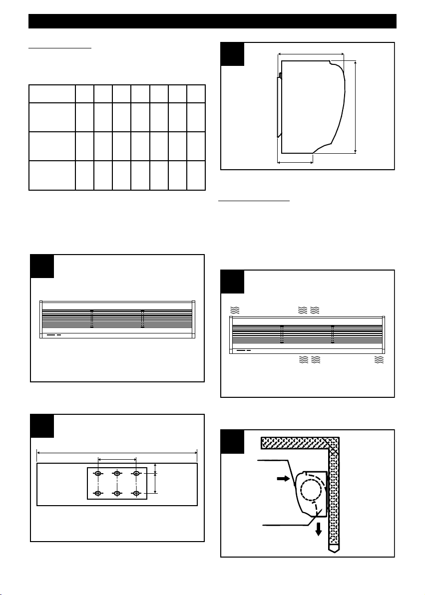
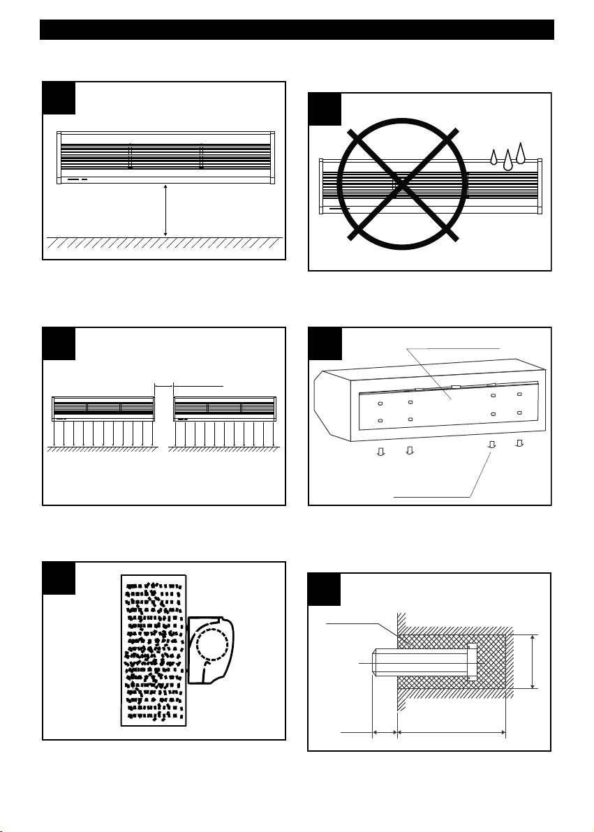
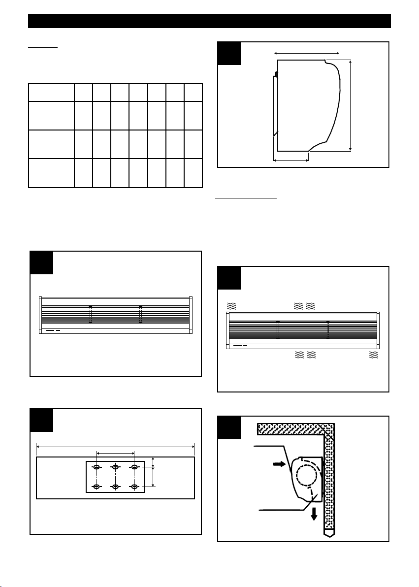
Dimensioni
Tabella, fig.1, 2, 3.
MODEL A B C D E F G
AD900
AD1200
AD1500
900 440 42 90 190 105 220
1200 440 42 90 190 105 220
1500 840 42 90 190 105 220
Installazione
Avvertenze
Durante l’installazione dell’apparecchio è necessario
tenere presenti le avvertenze riportate nel seguito:
• installare l’apparecchio in un luogo protetto per
garantirne la sicurezza ed evitarne l’oscillazione (fig.
4);
• installare l’apparecchio sempre all’interno di una
stanza (fig. 5);
5
Page 6
Calcestruzzo
13-15
mm
70 mm
Ø 40-50 mm
Piastra di montaggio
Vite di fissaggio
9 9
8 8
7 7
20 ~ 40 mm
6 6
>2,3 m
ITALIANO
installare l’apparecchio a non meno di 2,3 m dal
•
uolo (fig. 6);
s
• se l’accesso è più ampio dell’apparecchio, si
raccomanda di installare due o più unità in parallelo;
in questo caso è necessario lasciare uno spazio di
20-40 mm tra un’unità e l’altra (fig.7);
Non installare l’apparecchio in luoghi ove possa
•
ssere raggiunto da acqua, vapori, gas esplosivi o
e
orrosivi. (fig.9);
c
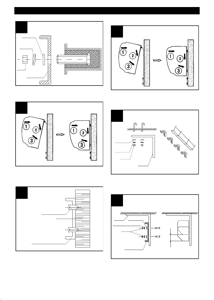
Montaggio
Rimuovere la piastra di montaggio svitando le viti
fissate sul retro del corpo centrale (fig.10);
• non lasciare spazi tra l’apparecchio e la parete. In
caso di installazione a soffitto utilizzare le staffe
(NON in dotazione). (fig. 8);
6
A Montaggio su parete in calcestruzzo
Fissare i bulloni nella posizione adeguata (stabilire
la posizione per mezzo della piastra di montaggio
e versare il cemento nei fori per i bulloni). Fig.11.
Quando il cemento si è solidificato posizionare la
piastra di montaggio, utilizzando la rondella e il
dado come indicato in fig.12.
Page 7
Max 10 cm
Piastra di
montaggio
Rondella
Rondella elastica
Dado
Staffa
&
'
&
Rondella
Rondella
elastica
Dado
Staffa
Vite per legno
Piastra di montaggio
Rondella
Rondella
e
lastica
Dado
Piastra di
montaggio
ITALIANO
Applicare il corpo centrale all’estremità più alta
della piastra di montaggio ed agganciarlo come
indicato in fig.13.
pplicare il corpo centrale come già descritto (fig.15)
A
C Montaggio a soffitto
Fissare le staffe per soffitto come indicato nella
fig.16.
B Montaggio su parete in legno
Fissare la piastra di montaggio nella posizione
adeguata con viti filettate: fig. 14.
Posizionare la piastra di montaggio sulle staffe
utilizzando i bulloni annessi, come illustrato in
fig.17. La posizione della piastra di montaggio può
essere regolata al massimo di 10 cm.
7
Page 8
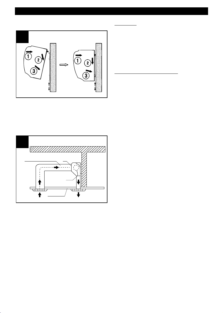
Soffitto
Condotto aria
In
Out
ITALIANO
pplicare il corpo centrale come già descritto.
A
fig.18)
(
C Montaggio al di sopra del soffitto
(controsoffitto)
Fissare la barriera d’aria eseguendo lo stesso
procedimento dell’installazione su parete in
calcestruzzo.
Effettuare i collegamenti delle tubazioni secondo
quanto riportato in fig.19.
Utilizzo
Le funzioni dell’apparecchio sono attivabili tramite il
telecomando in dotazione; esse sono, in sequenza:
N->velocità massima->velocità minima->OFF.
O
opo l’attivazione dell’apparecchio regolare la griglia
D
i uscita dell’aria per direzionare nel modo desiderato
d
il getto d’aria.
Manutenzione/pulizia
Prima di effettuare qualsiasi operazione di pulizia o
manutezione spegnere l’apparecchio e scollegarlo
dalla rete di alimentazione.
Non utilizzare prodotti chimici quali petrolio, benzene,
o diluenti per pulire l’apparecchio.
Non introdurre acqua o liquidi all’interno del motore
dell’apparecchio.
N.B. Nel caso di installazione a soffitto e
controsoffitto le prestazioni dell’apparecchio
potrebbere essere differenti da quelle dichiarate.
8
Page 9
ITALIANO
Informazione importante per lo
smaltimento ambientalmente
compatibile
IN ALCUNI PAESI DELL'UNIONE EUROPEA
UESTO PRODOTTO NON RICADE NEL CAMPO
Q
I APPLICAZIONE DELLA LEGGE NAZIONALE DI
D
RECEPIMENTO DELLA DIRETTIVA RAEE E
QUINDI NON È IN ESSI VIGENTE ALCUN OBBLIGO
DI RACCOLTA DIFFERENZIATA A FINE VITA.
Questo prodotto è conforme alla Direttiva
EU2002/96/EC.
Il simbolo del bidone barrato
riportato sull’apparecchio indica
che il prodotto, alla fine della
propria vita utile, dovendo essere
trattato separatamente dai rifiuti
domestici, deve essere conferito in
un centro di raccolta differenziata
per apparecchiature elettriche ed
elettroniche oppure riconsegnato al rivenditore al
momento dell’acquisto di una nuova apparecchiatura
equivalente.
L’utente è responsabile del conferimento
dell’apparecchio a fine vita alle appropriate strutture di
raccolta, pena le sanzioni previste dalla vigente
legislazione sui rifiuti.
L’adeguata raccolta differenziata per l’avvio
successivo dell’apparecchio dismesso al riciclaggio,
al trattamento e allo smaltimento ambientalmente
compatibile contribuisce ad evitare possibili effetti
negativi sull’ambiente e sulla salute e favorisce il
riciclo dei materiali di cui è composto il prodotto.
Per informazioni più dettagliate inerenti i sistemi di
raccolta disponibili, rivolgersi al servizio locale di
smaltimento rifiuti o al negozio in cui è stato effettuato
l’acquisto.
I produttori e gli importatori ottemperano alla loro
responsabilità per il riciclaggio, il trattamento e lo
smaltimento ambientalmente compatibile sia
direttamente sia partecipando ad un sistema collettivo
9
Page 10
ENGLISH
Description and use
You have purchased a room temperature air curtain,
which is part of the AIR DOOR family.
he aim of this type of appliance is to create a curtain
T
f air across doors or openings in general, in order to
o
eparate zones of different temperatures, by
s
preventing heat transfers between them without
limiting people or objects in terms of access.
These appliances are designed for industrial use,
where climatic separation between departments is
required (warehouses and production sites), in
offices, hospitals and laboratories, in the catering and
hospitality sector, and in bars, restaurants and shops
in general.
The AIR DOOR family consists of the following
models, in order of airflow:
AD900
AD1200
AD1500
All models have two speeds and a remote control
which controls all functions: power on/off, minimum
speed and maximum speed.
Safety
Warning:
this symbol indicated the need to
!
take precautions to prevent the user from harm
• Do not use this appliance for functions other than
those described in this booklet.
• After removing the appliance from its packaging,
make sure that it is complete and undamaged. If in
doubt contact a Vortice authorised technical
support centre. Do not leave packaging within reach
of children or disabled persons.
• Certain fundamental rules must be observed when
using any electrical appliance:
- never touch appliances with wet or damp hands;
- never touch appliances while barefoot;
- do not allow the unit to be operated by
unsupervised children or disabled persons.
• This appliance should not be perceived as suitable
for use by persons (including children) with reduced
physical, sensory or mental capacities, or in any
case lacking the necessary experience and skills,
unless supervised or previously instructed in its
operation by an individual who is responsible for
their safety. Children must always be supervised to
ensure that they do not play with the appliance.
• Place the appliance well away from children and
disabled persons when it is to be disconnected
from the electricity supply and no longer used.
• Do not use the appliance where there are
inflammable substances and vapours (alcohol,
insecticides, petrol, etc.).
• Do not use in potentially explosive environments.
• Internal cleaning of the appliance must only be
carried out by qualified personnel.
Caution:
this symbol indicates that care must
!
be taken to avoid damaging the appliance
Do not make modifications of any kind to this
•
appliance.
• The appliance must be installed by a professionally
qualified technician.
• Regularly inspect the appliance for visible defects. If
any faults are found, do not operate the appliance;
contact your Vortice authorised technical support
centre immediately.
• The mains power supply to which the units are
connected must comply with current laws.
• The appliance must be connected to an efficient
earthing system.
• The electrical power supply/socket to which the
appliance is to be connected must be able to
provide the maximum electrical power required by
the appliance. If it cannot do so, contact a
professionally qualified technician.
• The appliance power supply should include a
thermomagnetic protection device.
• A multi-pole switch must be used to install the
appliance. The gap between the switch contacts
must be no less than 3 mm.
• Do not cover or obstruct the air inlet or outlet grilles.
• Should the appliance be dropped or suffer a heavy
blow, have it checked immediately by your Vortice
authorized technical support centre.
• If the appliance does not function correctly or
develops a fault, switch it off immediately and
contact a Vortice authorised technical support
centre. Ensure that only genuine original Vortice
spares are used for any repairs.
• Position the fresh air inlet well away from sources of
pollution.
• Specifications for the power supply must
correspond to those on the appliance's electrical
data plate.
10
Page 11
5 5
External
Internal
Air inlet
Air outlet
4 4
3 3
G
E
F
A
B
C
D
2 2
1 1
ENGLISH
Sizes
Table, fig.1, 2, 3.
MODEL A B C D E F G
AD900
AD1200
AD1500
900 440 42 90 190 105 220
1200 440 42 90 190 105 220
1500 840 42 90 190 105 220
Installation
Caution
During appliance installation, take account of the
warnings provided below:
• Install the appliance in a sheltered place to
guarantee its safety and prevent it from oscillating
(fig.4).
• Always install the appliance inside the room (fig. 5);
11
Page 12

Concrete
13-15
mm
70 mm
Ø 40-50 mm
Mounting plate
Fixing screw
9 9
8 8
7 7
20 ~ 40 mm
6 6
>2,3 m
ENGLISH
install the appliance at least 2.3 m from the floor.
•
fig. 6);
(
• If the access area is larger than the appliance, we
recommend installing two or more units in parallel;
in this case, leave a gap of 20-40 mm between one
unit and the other (fig.7);
do not install the appliance in places where it could
•
ome into contact with water, vapours, explosive
c
ases or corrosive substances (fig.9);
g
Mounting
Remove the mounting plate by loosening the screws
fixed to the back of the central body (fig.10).
• do not leave gaps between the appliance and the
wall. In case of ceiling installation, use the brackets
(NOT included) (fig. 8);
12
A Mounting on concrete walls
Fix the bolts in the right position (establish this
position using the mounting plate and pour the
cement into the bolt holes) (fig.11).
When the cement has hardened, position the
mounting plate using the washer and nut as
indicated in the fig.12.
Page 13

Max 10 cm
Fixing
plate
Washer
Elastic washer
Nut
Bracket
&
'
&
Washer
Elastic
washer
Nut
Bracket
Wood screw
Fixing plate
Washer
Elastic
w
asher
Nut
Fixing
plate
ENGLISH
Apply the central body to the uppermost part of the
mounting plate and hook it on as indicated in the
fig.13.
pply the central body as described before (fig.15).
A
C Mounting on the ceiling
Fix the ceiling brackets in place, as indicated in the
fig.16.
B Mounting on wooden walls
Fix the mounting plate in the right position using
threaded screws (fig.14).
Position the mounting plate on the brackets using
the attached bolts, as illustrated in the fig.17. The
position of the mounting plate can be adjusted by
a maximum of 10 cm.
13
Page 14

Ceiling
Air duct
In
Out
ENGLISH
pply the central body as described before (fig.18).
A
C Mounting above the ceiling (false ceiling)
Fix the air curtain in place using the same
installation procedure as for concrete walls.
Connect the pipes as shown in the fig.19.
Operation
The appliance functions can be activated using the
remote control; these are, in order:
N->maximum speed->minimum speed->OFF.
O
fter activating the appliance, adjust the air outlet
A
rille to direct the jet of air as desired.
g
Maintenance/cleaning
Before carrying out any type of cleaning or
maintenance work, turn the appliance off and unplug
it from the power supply.
Do not use chemicals such as petroleum, benzene or
thinners to clean the appliance.
Do not let water or liquids enter the appliance motor.
NOTE: if mounting on the ceiling or above the ceiling,
appliance performance could vary with respect to the
stated values.
14
Page 15

ENGLISH
Important information on ecocompatible disposal
N CERTAIN EUROPEAN UNION COUNTRIES THIS
I
PRODUCT DOES NOT FALL WITHIN THE
REQUIREMENTS OF THE NATIONAL LAWS
IMPLEMENTING DIRECTIVE RAEE, AND IN THESE
COUNTRIES THE PRODUCT IS NOT SUBJECT TO
SEPARATE DISPOSAL OPERATIONS AT THE END
OF ITS WORKING LIFE.
This product complies with European Directive
2002/96/EC.
At the end of its useful life, the
product, marked with the crossed
out wheeled bin, must be
disposed of separately from urban
waste. It must be taken to a
differentiated disposal centre for
electrical and electronic
appliances or be returned to the retailer when a new
equivalent appliance is bought.
Subject to current legislation on waste disposal, the
user is legally responsible for taking the appliance at
the end of its useful life to a suitable disposal centre.
Appropriate differentiated waste collection for
subsequent recycling, treatment and environmentfriendly disposal of discarded equipment helps to
prevent possible negative environmental and health
effects and encourages recycling of the component
materials of the equipment.
For further information about available waste disposal
systems, contact your local waste disposal service or
the shop where you bought the product.
The manufacturers and importers comply with their
responsibility for recycling, treating, and
environmentally compatible disposal of waste both
directly and collectively.
15
Page 16

FRANCAIS
Description et mode d'emploi
L’appareil que vous venez d'acheter est un rideau
d'air à température ambiante qui appartient à la
amme des AIR DOOR.
g
es rideaux d'air servent à former une barrière
L
hermique au niveau des portes et des ouvertures afin
t
d'éviter le transfert de chaleur entre deux espaces à
des températures différentes, sans générer
d'obstacle à la circulation des personnes et des
objets.
Ils ont été étudiés pour l'industrie, quand une
séparation thermique est nécessaire entre certains
locaux (magasins et production), pour les bureaux,
les hôpitaux et les laboratoires, les salles de
restauration et d'accueil, les bars, les restaurants et
les commerces.
La gamme des AIR DOOR se compose des modèles
suivants, par débit d'air croissant :
AD900
AD1200
AD1500
Tous les modèles ont deux vitesses et sont munis
d'une télécommande qui gère l'ensemble de leurs
fonctions : mise en marche, vitesse minimale, vitesse
maximale, extinction.
Sécurité
Attention:
ce symbole indique la nécessité de prendre
quelques précautions pour la sécurité
!
de l‘utilisateur
• Ne pas utiliser cet appareil pour une fonction autre
que celle qui est indiquée dans le livret.
• Contrôler l'intégrité de l'appareil après l'avoir sorti
de son emballage : dans le doute, s'adresser
immédiatement à un Service après-vente agréé
Vortice. Placer les éléments de l'emballage hors de
portée des enfants ou des personnes handicapées.
• L'utilisation des appareils électriques implique le
respect de quelques règles fondamentales
notamment :
- ne pas toucher l'appareil avec les mains mouillées
ou humides
- ne pas toucher l'appareil pieds nus
- en interdire l'emploi aux enfants ou aux personnes
handicapées sans surveillance.
• Cet appareil ne doit pas être utilisé par des enfants
ou des personnes atteintes d'un handicap
physique, sensoriel ou mental ou inexpérimentées,
sauf sous la surveillance d'une personne
responsable de leur sécurité ou en suivant ses
instructions. Surveiller les enfants et veiller à ne pas
les laisser jouer avec l'appareil.
• Stocker l'appareil hors de portée des enfants et des
personnes handicapées quand il a été mis hors
tension et qu'on ne souhaite plus l'utiliser.
• Ne pas utiliser l'appareil à proximité de substances
ou de vapeurs inflammables (alcool, insecticide,
essence, etc.).
• Ne pas utiliser l'appareil en atmosphère explosive.
• Le nettoyage interne de l'appareil doit être confié
16
xclusivement à un professionnel qualifié.
e
Ne pas modifier l'appareil.
•
Avertissement:
ce symbole indique la nécessité de prendre
!
quelques précautions pour la sécurité
du produit
L'installation de l'appareil doit être réalisée par un
•
technicien qualifié.
• Contrôler régulièrement l'intégrité de l'appareil. Si
son état n'est pas satisfaisant, ne pas l'utiliser et
contacter immédiatement un Service après-vente
agréé Vortice.
• L'installation électrique à laquelle l'appareil est
raccordé doit être conforme aux normes en vigueur.
• L'appareil doit être relié à une installation efficace
de mise à la terre.
• Ne brancher l'appareil au réseau d'alimentation/à la
prise électrique que si la puissance de l'installation
ou de la prise est adaptée à sa puissance maximale.
Dans le cas contraire, s'adresser immédiatement à
un technicien qualifié.
• Il est nécessaire d'installer une protection magnétothermique adaptée sur l'alimentation électrique de
l'appareil.
• Dans ce but, prévoir un interrupteur omnipolaire
ayant une distance d'ouverture entre les contacts
supérieure ou égale à 3 mm.
• Ne pas couvrir ni obstruer les bouches d'aspiration
et de refoulement d'air.
• Si l'appareil tombe ou reçoit des coups violents, le
faire vérifier immédiatement par un Service aprèsvente agréé Vortice.
• En cas de disfonctionnement et/ou de panne,
éteindre immédiatement l'appareil et s'adresser à
un Service après-vente agréé Vortice. Exiger
l'emploi de pièces détachées d'origine pour toute
réparation.
• Sélectionner une entrée d'air frais à l'abri de toute
source de pollution.
• Les données électriques du réseau doivent
correspondre à celles qui sont inscrites sur la
plaquette appliquée sur l'appareil.
Page 17

5 5
Extérieur
Intérieur
Entrée d'air
Sortie d'air
4 4
3 3
G
E
F
A
B
C
D
2 2
1 1
FRANCAIS
Dimensions
Tableau, fig.1, 2, 3.
MODEL A B C D E F G
AD900
AD1200
AD1500
900 440 42 90 190 105 220
1200 440 42 90 190 105 220
1500 840 42 90 190 105 220
Installation
Avertissement
Pendant l'installation de l'appareil, suivre les
consignes ci-dessous:
• Installer l'appareil dans un endroit protégé où il soit
en sécurité, sans risque de déséquilibre (fig.4).
• Toujours installer l'appareil à l'intérieur d'une pièce
(fig. 5).
17
Page 18

Concrètes
13-15
mm
70 mm
Ø 40-50 mm
Plaque de montage
Vis de fixation
9 9
8 8
7 7
20 ~ 40 mm
6 6
>2,3 m
FRANCAIS
Installer l’appareil à 2,3 m du sol minimum (fig. 6).
•
• Si l'accès concerné est plus large que l'appareil, il
est recommandé d'installer deux unités ou plus en
parallèle. Dans ce cas, laisser un espace de 20-40
mm entre les unités (fig.7).
Ne pas installer l'appareil dans un local où il pourrait
•
tre exposé à l'eau, à des vapeurs, à des gaz
ê
xplosifs ou corrosifs (fig.9).
e
Montage
Ôter la plaque de montage et les vis fixées à l'arrière
du corps central (fig.10).
• Ne pas laisser d'espace entre l'appareil et le mur.
Pour une installation au plafond, utiliser des
attaches (qui NE SONT PAS fournies avec
l'appareil) (fig. 8).
18
A Montage sur un mur en béton
Fixer les boulons dans la position adéquate (définir
cette position à l'aide de la plaque de montage).
Verser du ciment dans les trous des boulons
(fig.11.)
Quand le ciment s'est solidifié, positionner la
plaque de montage avec la rondelle et l'écrou
comme le montre la fig.12.
Page 19

Max 10 cm
Plaque de
montage
Rondelle
Rondelle elastique
Ecrou
Staffa
&
'
&
Rondelle
Rondelle
elastique
Ecrou
Etrier
Vis à bois
Plaque de montage
Rondelle
Rondelle
é
lastique
Ecrou
P
laque de
montage
FRANCAIS
Appliquer le corps central de l’appareil sur
l'extrémité la plus haute de la plaque de montage
et l'accrocher comme le montre la fig.13.
ppliquer le corps central de l'appareil comme le
A
ontre la fig.15.
m
C Montage au plafond
Fixer les attaches pour plafond comme le montre la
fig. 16.
B Montage sur une cloison en bois
Fixer la plaque de montage dans la position
adéquate avec des vis filetées (fig. 14).
Positionner la plaque de montage sur les étriers en
utilisant les boulons joints, comme le montre la
figure suivante. La position de la plaque de
montage est réglable sur 10 cm max (fig.17).
19
Page 20

Plafond
Conduit d'air
In
Out
FRANCAIS
ppliquer le corps central de l'appareil en suivant
A
es instructions données plus haut (fig.18).
l
C Montage dans un faux-plafond
Fixer le rideau d'air en suivant la même procédure
d'installation que pour les murs en béton.
Raccorder les tubes comme le montre la fig. 19
Mode d’emploi
Les fonctions de l'appareil s'activent avec la
télécommande de série dans l'ordre suivant :
N->vitesse maximale ->vitesse minimale ->OFF.
O
près avoir mis l'appareil en marche, régler la grille de
A
ortie d'air pour diriger le débit dans le sens souhaité.
s
Entretien/Nettoyage
Avant toute opération de nettoyage ou d'entretien,
éteindre l'appareil et débrancher la prise du réseau
électrique.
Ne pas utiliser de produit chimique, de pétrole,
d'essence ou de diluant pour nettoyer l'appareil.
Ne pas introduire d'eau ou de liquide dans le moteur
de l'appareil.
N.B. Quand l'appareil est posé au plafond ou dans un
faux-plafond, ses performances peuvent être
différentes de celles qui sont indiquées sur la
plaquette.
20
Page 21

FRANCAIS
Information importante pour
éliminer l’appareil en respectant l’environnement
DANS CERTAINS PAYS DE L’UNION
UROPÉENNE, CET APPAREIL N’ENTRE PAS
E
ANS LE CHAMP DE TRANSPOSITION DE LA
D
DIRECTIVE DEEE, IL N’EXISTE DONC AUCUNE
OBLIGATION DE COLLECTE DIFFÉRENCIÉE À LA
FIN DE SON CYCLE DE VIE.
Cet appareil est conforme à la Directive
EU2002/96/EC.
Le symbole du bidon barré
apposé sur l’appareil indique que,
lors de sa mise au rebut, il doit
être traité séparément des
déchets domestiques et remis à
un centre de collecte différenciée
pour équipements électriques et
électroniques ou au revendeur, lors de l’achat d’un
nouvel appareil.
L’utilisateur est responsable de la remise de l’appareil
à la fin de son cycle de vie aux structures de collecte
appropriées, sous peine des sanctions prévues par la
loi en matière de traitement des déchets.
La collecte différenciée, en permettant de recycler
l’appareil, de le retraiter et de l’éliminer en respectant
l’environnement, contribue à éviter la pollution du
milieu et ses effets sur la santé et favorise la
réutilisation des matériaux qui le composent.
Pour plus d’informations sur les systèmes de collecte
existants, s’adresser au service local d’élimination
des déchets ou au magasin dans lequel l’appareil a
été acheté.
Les producteurs et les importateurs satisfont à leurs
obligations environnementales en matière de
recyclage, de traitement et d’élimination des déchets,
directement ou en participant à un système collectif.
21
Page 22

DEUTSCH
Beschreibung und Gebrauch
Bei dem von Ihnen erworbenen Gerät handelt es sich
um einen Luftschleier mit Raumtemperatur der
erätefamilie AIR DOOR.
G
iese Geräte dienen zur Schaffung einer Barriere aus
D
trömender Luft an Türen oder in Eingangsbereichen
s
im Allgemeinen, mit der Luftmassen unterschiedlicher
Temperatur voneinander getrennt werden, um deren
Austausch zu verhindern und gleichzeitig das
ungehinderte Passieren von Personen und
Gegenständen zu ermöglichen.
Diese Geräte wurden für den Einsatz in der Industrie
entwickelt, wo die klimatische Trennung der
Abteilungen (Lager und Produktionsabteilungen)
erforderlich ist, aber auch in Büroräumen, in
Krankenhäusern und Labors, in Gastronomie- und
Empfangsbereichen, in Cafés und Restaurants sowie
in Läden im Allgemeinen.
Die Gerätefamilie AIR DOOR setzt sich aus den
folgenden Modellen mit steigender Leistung
zusammen:
AD900
AD1200
AD1500
Alle Modelle verfügen über zwei
Geschwindigkeitsstufen und Fernbedienung, mit der
sämtliche Funktionen gesteuert werden können:
Einschaltung, Mindestgeschwindigkeit,
Höchstgeschwindigkeit, Ausschaltung.
Sicherheit
Achtung:
dieses Symbol zeigt Vorsichtsmaßnahmen an
!
um Schäden am Bediener zu vermeiden
• Dieses Gerät darf nur für den in der vorliegenden
Anleitung angegebenen Verwendungszweck
eingesetzt werden.
• Das Gerät nach dem Auspacken auf
Transportschäden oder andere Mängel untersuchen
und im Zweifelsfall sofort den VorticeVertragskundendienst verständigen. Das
Verpackungsmaterial nicht in Reichweite von
Kindern oder Personen lassen, die sich damit
schaden könnten.
• Beim Einsatz von Elektrogeräten jeder Art müssen
einige Grundregeln stets beachtet werden, wie
unter anderem:
- Nicht mit nassen oder feuchten Händen berühren;
- nicht barfuß berühren;
- Nicht unbeaufsichtigt von Kindern oder Personen,
die sich damit schaden könnten, benutzen lassen.
• Dieses Gerät ist nicht für den Gebrauch durch
Personen (einschließlich Kinder) mit
eingeschränkten körperlichen, sensorischen oder
geistigen Fähigkeiten bzw. fehlender Erfahrung und
Kenntnis bestimmt, es sei denn er erfolgt unter
Aufsicht oder Anweisung hinsichtlich der
Verwendung des Geräts durch eine für ihre
Sicherheit verantwortliche Person. Kinder sollten
beaufsichtigt werden, um sicherzustellen, dass sie
nicht mit dem Gerät spielen.
22
Das Gerät außerhalb der Reichweite von Kindern
•
nd Personen, die sich damit schaden könnten,
u
ufbewahren, wenn es vom Stromnetz getrennt und
a
nicht mehr benutzt werden soll.
• Das Gerät nicht in der Nähe entflammbarer
ubstanzen oder Dämpfe wie Alkohol, Insektizide,
S
Benzin usw. verwenden.
• Nicht in explosionsgefährdeten Bereichen
verwenden.
Das Geräteinnere darf nur von qualifiziertem
•
Fachpersonal gereinigt werden.
• Keine Änderungen am Gerät vornehmen.
Hinweis:
dieses Symbol zeigt Vorsichtsmaßnahmen an
!
um Schäden am Gerät zu vermeiden
• Die Installation des Geräts darf nur durch
qualifiziertes Fachpersonal erfolgen.
• Regelmäßig den einwandfreien Zustand des Geräts
überprüfen. Bei festgestellten Mängeln das Gerät
nicht benutzen und sofort den VorticeVertragskundendienst aufsuchen.
• Die elektrische Anlage, an die das Gerät
angeschlossen wird, muss den geltenden
Vorschriften entsprechen.
• Das Gerät muss korrekt geerdet werden.
• Das Gerät nur dann an das Stromnetz/an die
Steckdose anschließen, wenn die Stromfestigkeit
der Anlage/Steckdose für die maximale
Geräteleistung geeignet ist. Sollte dies nicht der Fall
sein, sofort qualifiziertes Fachpersonal hinzuziehen.
• An der Zuleitung des Geräts muss ein geeigneter
thermomagnetischer Schutzschalter eingebaut
werden.
• Bei der Installation ist ein allpoliger Schalter mit
einer Kontaktöffnungsweite von mindestens 3 mm
vorzusehen.
• Die Ansaug- und Ausblasgitter des Geräts stets
freihalten.
• Fällt das Gerät hinunter oder wurde es starken
Stößen ausgesetzt, muss es sofort vom VorticeVertragskundendienst überprüft werden.
• Bei Betriebsstörungen und/oder defektem Gerät
sofort den Vortice-Vertragskundendienst aufsuchen
und für eine eventuelle Reparatur die Verwendung
von Vortice-Originalersatzteilen verlangen.
• Die Position des Zulufteintritts muss fern von
verschmutzten Quellen gewählt werden.
• Die elektrischen Daten der Netzversorgung müssen
den Daten des am Gerät angebrachten
Typenschilds entsprechen.
Page 23

5 5
Extern
Intern
Lufteinlass
Luftaustritt
4 4
3 3
G
E
F
A
B
C
D
2 2
1 1
DEUTSCH
Abmessungen
Tabelle, Abb.1, 2, 3.
MODEL A B C D E F G
AD900
AD1200
AD1500
900 440 42 90 190 105 220
1200 440 42 90 190 105 220
1500 840 42 90 190 105 220
Installation
Hinweis
Während der Installation des Geräts sind die
folgenden Hinweise zu beachten:
• Das Gerät an einem geschützten Ort installieren, um
seine Sicherheit und stabile Position zu garantieren
(Abb. 4).
• Das Gerät immer im Rauminnern installieren (Abb.
5).
23
Page 24

Beton
13-15
mm
70 mm
Ø 40-50 mm
Montageplatte
Befestigungsschraube
9 9
8 8
7 7
20 ~ 40 mm
6 6
>2,3 m
DEUTSCH
Das Gerät auf mindestens 2,3 m Höhe vom Boden
•
nstallieren (Abb. 6).
i
• Wenn der Eingangsbereich größer als das Gerät ist,
sollten unbedingt zwei oder mehr Geräte parallel
installiert werden; in diesem Fall muss zwischen
den Geräten jeweils ein Freiraum von 20-40 mm
gelassen werden (Abb. 7).
Das Gerät nicht an Orten installieren, an denen es
•
asser, Dämpfen, explosiven oder korrosiven
W
asen ausgesetzt ist (Abb. 9).
G
Montage
Die Schrauben an der Rückseite des mittleren
Geräteteils lösen und die Montageplatte entfernen
(Abb.10);
• Keinen Freiraum zwischen Gerät und Wand lassen.
Bei Installation an der Decke die Haltebügel
verwenden (NICHT im Lieferumfang enthalten)
(Abb. 8).
24
A Montage an einer Betonwand
Die Mutterschrauben in der passenden Position
befestigen (die Position mithilfe der Montageplatte
bestimmen und den Zement in die Öffnungen für
die Mutterschrauben füllen) (Abb.11).
Sobald der Zement erhärtet ist, die Montageplatte
anbringen; dazu die Unterlegscheibe und die
Page 25

Max 10 cm
Montageplatte
Scheibe
Federscheibe
Nuss
Bügel
&
'
&
Scheibe
Federscheibe
Nuss
Steigbügel
Holzschraube
Montageplatte
Scheibe
Feders
cheibe
Nuss
Montageplatte
DEUTSCH
utter wie nachstehend abgebildet verwenden
M
Abb.12).
(
Das mittlere Geräteteil am obersten Ende der
Montageplatte anbringen und wie abgebildet
einhängen (Abb.13).
as mittlere Geräteteil wie bereits beschrieben
D
nbringen (Abb.15).
a
C Deckenmontage
Die Deckenhalterungen wie nachstehend
abgebildet befestigen (Abb. 16).
B Montage an einer Holzwand
Die Montageplatte mit Schrauben in der
passenden Position befestigen (Abb. 14).
Die Montageplatte mithilfe der beiliegenden
Mutterschrauben an den Halterungen positionieren
wie nachstehend abgebildet. Die Position der
Montageplatte kann um max. 10 cm verstellt
werden (Abb.17).
25
Page 26

Decke
Luftkanal
In
Out
DEUTSCH
as mittlere Geräteteil wie bereits beschrieben
D
nbringen (Abb. 18).
a
C Montage über der Decke (Zwischendecke)
Den Luftschleier befestigen. Dazu genauso
vorgehen wie bei der Installation an der
Betonwand.
Die Rohre wie unten abgebildet verbinden
(Abb.19).
Gebrauch
Die Funktionen des Geräts können mit der
Fernbedienung aktiviert werden, und zwar der
eihenfolge: ON->Höchstgeschwindigkeit-
R
Mindestgeschwindigkeit->OFF.
>
ach der Aktivierung des Geräts das Ausblasgitter so
N
einstellen, dass der Luftstrahl in die gewünschte
Richtung gelenkt wird.
Wartung/Reinigung
Prima di effettuare qualsiasi operazione di pulizia o
manutezione spegnere l’apparecchio e scollegarlo
dalla rete di alimentazione.
Non utilizzare prodotti chimici quali petrolio, benzene,
o diluenti per pulire l’apparecchio.
Non introdurre acqua o liquidi all’interno del motore
dell’apparecchio.
Hinweis
Bei Installation an Decke oder Zwischendecke
könnten die Leistungen des Geräts von den Angaben
abweichen.
26
Page 27

DEUTSCH
Wichtige information für die
umweltgerechte Entsorgung
IN EINIGEN EU-LÄNDERN GELTEN FÜR DIESES
PRODUKT NICHT DIE VORGABEN DER
UROPÄISCHEN RICHTLINIE ÜBER ELEKTRO-
E
ND ELEKTRONIK-ALTGERÄTE (WEEE-
U
RICHTLINIE) UND DEMNACH BESTEHT IN DIESEN
LÄNDERN AUCH KEINE PFLICHT FÜR DIE
MÜLLTRENNUNG BEI DER ENTSORGUNG DES
GERÄTES.
Dieses Gerät entspricht der EG-Richtlinie
2002/96/EG.
Das Symbol mit der
durchgestrichenen Abfalltonne am
Gerät bedeutet, dass das Gerät
nach seiner Aussonderung nicht
im Haushaltsmüll entsorgt werden
darf, sondern an einer
Sammelstelle für Elektro- und
Elektronikgeräte oder beim Kauf
eines gleichwertigen Neugerätes beim Händler
abzugeben ist.
Der Benutzer hat Sorge zu tragen, dass das Gerät
nach seiner Aussonderung an einer geeigneten
Sammelstelle abgegeben wird.Ein Nichtbeachten
dieser Vorschrift ist gemäß der geltenden
Abfallordnung strafbar.
Das geeignete Sortieren von Abfall und nachfolgende
Recyceln des aussortierten Gerätes zur
umweltverträglichen Entsorgung trägt zum Schutz von
Umwelt und Gesundheit bei und dient der
Wiederverwendung der recyclingfähigen Materialien,
aus denen das Gerät besteht.
Für detailliertere Informationen bezüglich der
verfügbaren Sammelsysteme wenden Sie sich an Ihre
örtliche Behörde oder an den Händler, bei dem Sie
das Gerät gekauft haben.
Die Hersteller und Importeure kommen ihrer
Verpflichtung zum umweltfreundlichen Recycling,
Verarbeiten und Entsorgen sowohl direkt als auch
durch Teilnahme an einem Kollektivsystem nach.
27
Page 28

ESPAÑOL
Descripción y uso
El aparato que usted ha comprado es una barrera de
aire a temperatura ambiente perteneciente a la familia
e las AIR DOOR.
d
a función de este tipo de aparato es crear una
L
arrera de aire en coincidencia con puertas o
b
aberturas en general, para separar zonas de distinta
temperatura, impidiendo la transferencia térmica de
una zona a otra, sin obstaculizar el acceso de
personas o cosas.
Estos aparatos están diseñados para emplearse en la
industria, donde es necesaria la separación climática
entre distintas divisiones (almacenes y fábricas),
como así también en oficinas, hospitales,
laboratorios, comedores y locales de recepción,
bares y restaurantes, tiendas en general.
La familia de las AIR DOOR incluye los siguientes
modelos, con caudales de aire crecientes:
AD900
AD1200
AD1500
Todos los modelos tienen dos velocidades y un
mando a distancia para gestionar todas las
funciones: encendido, velocidad mínima, velocidad
máxima, apagado.
Seguridad
Atención:
este simbolo indica precauciones que sirven
!
para evitar daños al usuario
• No emplear el producto con fines distintos de
aquellos previstos en este manual.
• Una vez extraído el producto del embalaje,
comprobar su integridad: en caso de duda,
contactar inmediatamente con un Centro de
Asistencia Técnica autorizado Vortice. No dejar el
embalaje al alcance de niños o personas con
discapacidad.
• El empleo de cualquier aparato eléctrico implica el
cumplimiento de algunas reglas fundamentales,
entre las que destacamos:
- no tocarlo con las manos mojadas o húmedas;
- no tocarlo con los pies descalzos;
- no permitir que los niños o las personas con
discapacidad lo utilicen sin ser vigiladas.
• Este aparato no es adecuado para el uso por parte
de niños o de personas con capacidades físicas,
sensoriales o psíquicas reducidas, o carentes de la
experiencia y los conocimientos necesarios para
utilizarlo, salvo bajo la vigilancia y las instrucciones
de una persona responsable de su seguridad. No
permitir que los niños jueguen con el aparato.
• Guardar el aparato lejos del alcance de los niños y
de personas discapacitadas en el momento en que
se decida desconectarlo de la red eléctrica y no
utilizarlo más.
• No utilizar el aparato cerca de sustancias o vapores
inflamables como alcohol, insecticidas, gasolina,
etc.
• No utilizar el aparato en ambientes explosivos.
28
La limpieza interna del aparato tiene que ser
•
fectuada por personal cualificado.
e
Advertencia:
este simbolo indica precauciones que sirven
!
para evitar daños en el producto
• No aportar al aparato modificaciones de ningún
ipo.
t
• El aparato debe ser instalado por personal
profesional cualificado.
• Verificar periódicamente la integridad del aparato.
En caso de anomalías, no emplear el aparato;
ponerse en contacto inmediatamente con un
Centro de Asistencia Técnica autorizado Vortice.
• La instalación eléctrica a la que se ha de conectar
el aparato debe ser conforme con las normas
vigentes.
• El aparato se ha de conectar a una toma de tierra.
• Conectar el aparato a la red de alimentación
eléctrica o a una toma de corriente sólo si la
capacidad de la instalación o la toma es adecuada
a su potencia máxima. En caso contrario, recurrir
inmediatamente a personal profesional cualificado.
• Es necesario instalar en la alimentación del aparato
una protección magnetotérmica adecuada.
• La instalación requiere un interruptor omnipolar con
distancia de apertura entre los contactos igual o
superior a 3 mm.
• No cubrir ni obstruir las rejillas de entrada y salida
del aire.
• Si el aparato se cae o recibe un golpe fuerte, llevarlo
inmediatamente a un Centro de Asistencia Técnica
autorizado Vortice.
• Si el aparato no funciona correctamente o se avería,
apagarlo de inmediato y contactar con un Centro de
Asistencia Técnica autorizado Vortice. En caso de
reparación, exigir el empleo de repuestos originales
Vortice.
• Seleccionar un punto de entrada del aire fresco que
se encuentre lejos de fuentes contaminantes.
• Los datos eléctricos de la red deben coincidir con
aquellos indicados en la placa de datos eléctricos
del aparato.
Page 29

5 5
Externo
Interno
Entrada de aire
Salida de aire
4 4
3 3
G
E
F
A
B
C
D
2 2
1 1
ESPAÑOL
Dimensiones
Tabla, fig.1, 2, 3.
MODEL A B C D E F G
D900
A
900 440 42 90 190 105 220
AD1200
AD1500
1200 440 42 90 190 105 220
1500 840 42 90 190 105 220
Instalación
Advertencias
Para instalar el aparato es necesario tener en cuenta
las siguientes advertencias:
• Instalar el aparato en un lugar protegido para
garantizar la seguridad y evitar la oscilación (fig. 4);
• Instalar el aparato en el interior de una habitación
(fig. 5);
29
Page 30

Cemento
13-15
mm
70 mm
Ø 40-50 mm
Placa de montaje
Tornillo de fijación
9 9
8 8
7 7
20 ~ 40 mm
6 6
>2,3 m
ESPAÑOL
Instalar el aparato a no menos de 2,3 m del suelo.
•
fig. 6).
(
• Si el acceso es más amplio que el aparato, instalar
dos o más unidades en paralelo; en este caso es
necesario dejar un espacio de 20-40 mm entre las
unidades (fig.7).
No instalar el aparato en lugares donde pueda
•
aber agua, vapores, gases explosivos o corrosivos
h
fig.9).
(
Montaje
Sacar la placa de montaje desenroscando los
tornillos fijados en la parte posterior del cuerpo
central (fig.10);
• No dejar espacio entre el aparato y la pared. En
caso de instalación de techo, utilizar soportes (NO
en dotación) (fig. 8).
30
A Montaje sobre pared de hormigón
Fijar los pernos en la posición adecuada
(establecer la posición por medio de la placa de
montaje y verter el cemento en los orificios para los
pernos) Fig.11.
Cuando el cemento se haya solidificado, poner la
placa de montaje utilizando la arandela y la tuerca
Page 31

Max 10 cm
Placa de
montaje
Rondana
Rondana elastica
Nuez
Estribo
&
'
&
Rondana
Rondana
elastica
Nuez
Estribo
Madera tornillo
Placa de montaje
R
ondana
R
ondana
elastica
N
uez
Placa de
montaje
ESPAÑOL
omo se indica en la fig.12.
c
Aplicar el cuerpo central al extremo superior de la
placa de montaje y engancharlo como se indica en
la fig.13.
plicar el cuerpo central como se indica en la fig.15.
A
C Montaje de techo
Fijar los soportes de techo como se indica en la
figura siguiente (fig.16).
B Montaje sobre pared de madera
Fijar la placa de montaje en la posición adecuada
con tornillos: fig. 14.
Poner la placa de montaje sobre los soportes
utilizando los pernos suministrados como se indica
en la figura siguiente. La posición de la placa de
montaje se puede ajustar como máximo 10 cm
(fig.17).
31
Page 32

Tec h o
Conducto de aire
In
Out
ESPAÑOL
plicar el cuerpo central como se describió
A
nteriormente (fig.18).
a
C Montaje dentro del cielorraso
Fijar la barrera de aire siguiendo el mismo
procedimiento que para la instalación sobre pared
de hormigón.
Efectuar las conexiones de los tubos como se
indica en la fig.19.
Uso
Las funciones del aparato se pueden activar con el
mando a distancia y son las siguientes:
N->velocidad máxima->velocidad mínima->OFF.
O
ig.20
F
na vez activado el aparato, regular la rejilla de salida
U
del aire para orientar el chorro de aire como se desee.
Mantenimiento/limpieza
Antes de realizar cualquier operación de limpieza o
mantenimiento hay que apagar y desconectar el
aparato de la red de alimentación.
No utilizar productos químicos como petróleo,
gasolina o diluyentes para limpiar el aparato.
No introducir agua o líquidos en el motor del aparato.
NOTA En caso de instalación de techo y en
cielorraso, las prestaciones del aparato podrían
resultar diferentes de los valores declarados.
32
Page 33

ESPAÑOL
Información importante sobre
eliminación respetuosa con el
medio ambiente
EN ALGUNOS PAÍSES DE LA UNIÓN EUROPEA
STE PRODUCTO NO ESTÁ INCLUIDO EN EL
E
ÁMBITO DE APLICACIÓN DE LA LEY NACIONAL
QUE TRASPONE LA DIRECTIVA RAEE Y, POR LO
TANTO, NO EXISTE OBLIGACIÓN ALGUNA DE
RECOGIDA SELECTIVA AL FINALIZAR SU VIDA
ÚTIL.
Este producto cumple los requisitos de la Directiva
EU2002/96/EC.
El símbolo del contenedor de
basura tachado, que hay sobre el
aparato, indica que no puede ser
eliminado con los desechos
domésticos al finalizar su vida útil.
Se ha de llevar a un punto
derecogida selectiva para
aparatos eléctricos o electrónicos
o entregar al proveedor durante la compra de un
aparato equivalente.
El usuario deberá llevar el aparato a un punto de
recogida selectiva para su eliminación, de lo contrario
se aplicarán las sanciones previstas por las normas
sobre eliminación de desechos.
La recogida selectiva para la reutilización, tratamiento
y eliminación respetuosa con el medio ambiente del
aparato ayuda a evitar los efectos sobre el medio
ambiente y la salud y favorece el reciclaje de los
materiales que componen el producto.
Para más información sobre los sistemas de
eliminación disponibles, contactar con el servicio local
de eliminación de desechos o con la tienda que
vendió el aparato.
Los fabricantes y los importadores cumplen con su
responsabilidad de recuperación, tratamiento y
eliminación respetuosa con el medio ambiente
directamente o participando a un sistema colectivo.
La Vortice S.p.A. si riserva il diritto di apportare tutte le varianti migliorative ai prodotti in corso di vendita.
Vortice S.p.A. reserves the right to make improvements to products at any time and without prior notice.
La société Vortice S.p.A. se réserve le droit d'apporter toutes les variations afin d'améliorer ses produits en cours de commercialisation.
Die Firma Vortice S.p.A. behält sich vor, alle eventuellen Verbesserungsänderungen an den Produkten des Verkaufsangebots vorzunehmen.
Vortice se reserva el derecho de incorporar todas las mejoras necesarias a los productos en fase de venta.
Page 34

Para ejercer la garantía , el Cliente debe completar y devolver a VORTICE LATAM ,
dentro de los 8 días posteriores a la compra , la "Parte 2 " de la Garantía , la
dirección y en la forma prevista en esta parte . La "Parte 1 " de la tarjeta de garantía
debe ser conservada y presentada, junto con el documento
scal (factura o recibo)
expedida por el vendedor en el momento de la compra, al Servicio Post-Venta de
Vortice Latam , que realizará el trabajo de garantía . Los servicios prestados en
garantía no amplían el período de garantía.
The “Part 1” must be attached to the appliance when it needs to be returned for
servicing.
ATTENTION Guarantee is only valid if all details are completed correctly.
FECHA DE ENVÍO
Mailing date
__________________
EMPAQUE
_________________
PRUEBA
SELLO DEL DISTRIBUIDOR
name and address of supplier
GARANTIA - GUARANTEE
PARA SER CONSERVADO
to be retained
AÑOS
YEARS
2
Exclusiones
Esta garantía no cubre:
• Los daños causados por el transporte.
• Defectos o daños derivados del uso incorrecto o inadecuado por parte del cliente.
• Defectos causados por no seguir las advertencias y condiciones de uso, como se indica en el
manual de instrucciones que acompaña al producto.
• Los defectos resultantes de la instalación incorrecta o por una instalación sin cumplir con las
disposiciones de la sección correspondiente del manual de instrucciones.
• Las fallas causadas por una mala conexión a la red eléctrica o tensión de alimentación distinta
a la especi
cada para esta unidad.
Esta garantía no cubre, además, los posibles defectos derivados del mantenimiento o
reparaciones de
cientes realizadas por personal no cali cado o por terceros no autorizados.
1
Page 35

DATOS DEL USUARIO/CUSTOMER DATA
nombre/name _____________________________________________________________
apellido/surname ________________________________________________________
calle/street _____________________________________________________________
código postal/post code ___________________________________________________
ciudad/town ______________________________________________________________
Declaro tener conocimiento de las condiciones de garantía especi
cadas en el
certi
cado en mi poder y autorizo el manejo de mis datos personales.
Firma/signed _____________________________________________________________
(Por favor escriba con letra de molde/please use block letters)
FECHA DE ENVÍO
Mailing date
___________________________________
ARTICULO COMPRADO EN
Date of purchase
_______________________________
SELLO DEL DISTRIBUIDOR
name and address of supplier
2
GARANTIA - GUARANTEE
PARA ENVIAR
DENTRO DE LOS 8 DÍAS POSTERIORES A LA COMPRA
to send (within 8 days from date of purchase)
AÑOS
YEARS
2
Page 36

LATAM AREA
Enviar por favor la garantía a la dirección:
Vortice Latam S.A.
3er Piso, O
cina 9-B
Edi
cio Meridiano
Guachipelín, Escazú
San José, Costa Rica
PO Box 10-1251
Autorizo a Vortice E l e t t r o s o c i a l i
S.p.A. y a los distribuidores de los
productos Vortice a incluir mis datos
en sus listas y comunicarlos a
terceros para el envío de material
publicitario e informativo. En todo
momento, según las leyes vigentes
en mi país, podré tener libre acceso
a mis datos, pedir su modi
cación o
cancelación o bien oponerme a su
utilización escribiendo a la dirección
del revendedor del país donde el
aparato ha sido adquirido.
No autorizo
(marcar si interesa).
OTHER COUNTRIES
Please send the guarantee to the retailer’s
address in the country where the appliance
has been purchased.
I authorise Vortice Elettrosociali
S.p.A. and its local distributors to
include my personal details within
their database and they can use
it through a third party for the
despatch of advertising material. At
any time, in accordance with the
regulations in force within my
country. I can have access to details
and can ask to make changes, or
prohibit the usage of my details.This
will be done by addressing my
request directly to the headquarters
of the local distributor where the
appliance has been bought.
I do not authorize
(please tick here if required).
 Loading...