

Page 1
Operating Instructions and Parts Manual RMV Series Pumps
Firs t Cho ice Wh en Qua lity Matter s
NORTH
AMERICA
High Performance Pumps
Operating Instructions and Parts Manual RMV Series Pumps
Plunger Pumps
Please read and save these instructions. Read carefully before attempting to assemble, install,
operate or maintain the product described. Protect yourself and others by observing all safety
information. Failure to comply with instructions could result in personal injury and/or property
damage! Retain instructions for future reference.
Description
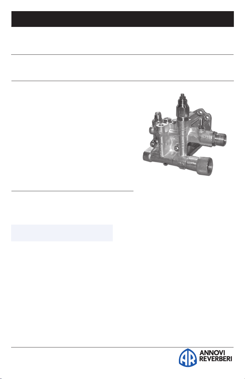
This plunger pump will pump up to 2.5 GPM
at 2500 PSI. It spins at 3400 RPM in a direct
drive system coupled with a gasoline engine.
The matching flange provides convenient
connection to most 3/4” shaft 1.1 - 5.5 HP
engines. The hollow shafted pump includes
a built-in pressure control valve, and
chemical injection system.
RMV 3400 rpm D Version
Model Max GPM Max PSI
RMV2G20D 2.0 2000
RMV2G23B 2.0 2300
RMV2G25D 2.0 2500
RMV2.5G20D 2.5 2000
RMV2.5G23B 2.5 2300
RMV2.5G25D 2.5 2500
Special Note: Use only AR64545 for the XJ/SJ/BK/RMV Series pumps only: Do NOT change
oil. Use oil only to add if low. This oil is a specially formulated synthetic with special
additives for the demands of the XJ, SJ, BK and RMV pump series. No other oil is factory
approved for these pumps, and could result in pump failure.
Form RMV-OM 806
Figure 1 - RMV
Page 2
Firs t Cho ice Wh en Qua lity Matter s
NORTH
AMERICA
Operating Instructions and Parts Manual RMV Series Pumps
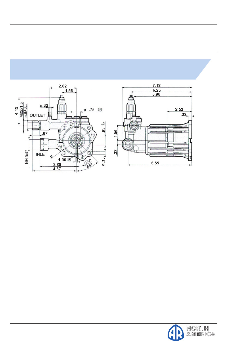
RMV
D version
Hollow shaft pump ø 3/4”
Plunger Pumps
Page 3
Operating Instructions and Parts Manual RMV Series Pumps
Firs t Cho ice Wh en Qua lity Matter s
NORTH
AMERICA
Plunger Pumps
SPRAY NOZZLE CHART
Nozzle 1000 1200 1400 1600 1800 2000 2200 2400 2600 2800 3000 3200 3400 3600 3700 4000 4200 4400 4600 4800 5000
# PSI PSI PSI PSI PSI PSI PSI PSI PSI PSI PSI PSI PSI PSI PSI PSI PSI PSI PSI PSI PSI
2.0 1.00 1.10 1.18 1.26 1.34 1.41 1.48 1.55 1.61 1.67 1.73 1.79 1.84 1.90 1.92 2.00 2.05 2.10 2.14 2.19 2.40
2.25 1.13 1.23 1.33 1.42 1.51 1.59 1.67 1.74 1.81 1.88 1.95 2.01 2.07 2.13 2.16 2.25 2.31 2.36 2.41 2.46 2.52
2.5 1.25 1.37 1.48 1.58 1.68 1.77 1.85 1.94 2.02 2.09 2.17 2.24 2.30 2.37 2.40 2.50 2.56 2.62 2.68 2.74 2.80
2.75 1.38 1.51 1.63 1.74 1.84 1.94 2.04 2.13 2.22 2.30 2.38 2.46 2.54 2.61 2.64 2.75 2.82 2.88 2.95 3.01 3.07
3.0 1.50 1.64 1.77 1.90 2.01 2.12 2.22 2.32 2.42 2.51 2.60 2.68 2.77 2.85 2.89 3.00 3.07 3.15 3.22 3.29 3.35
Operating Instructions and Parts Manual RMV Series Pumps
3.25 1.63 1.78 1.92 2.06 2.18 2.30 2.41 2.52 2.62 2.72 2.81 2.91 3.00 3.08 3.13 3.25 3.33 3.41 3.49 3.56 3.63
3.5 1.75 1.92 2.07 2.21 2.35 2.47 2.60 2.71 2.82 2.93 3.03 3.13 3.23 3.32 3.37 3.50 3.59 3.67 3.75 3.83 3.91
4.0 2.00 2.19 2.37 2.53 2.68 2.83 2.97 3.10 3.22 3.35 3.46 3.58 3.69 3.79 3.85 4.00 4.10 4.20 4.29 4.38 4.47
4.5 2.25 2.46 2.66 2.85 3.02 3.18 3.34 3.49 3.63 3.76 3.90 4.02 4.15 4.27 4.33 4.50 4.61 4.72 4.83 4.93 5.03
5.0 2.50 2.74 2.96 3.16 3.35 3.54 3.71 3.87 4.03 4.18 4.33 4.47 4.61 4.74 4.81 5.00 5.12 5.24 5.36 5.48 5.59
5.5 2.75 3.01 3.25 3.48 3.69 3.89 4.08 4.26 4.43 4.60 4.76 4.92 5.07 5.22 5.29 5.50 5.64 5.77 5.90 6.02 6.15
6.0 3.00 3.29 3.55 3.79 4.02 4.24 4.45 4.65 4.84 5.02 5.20 5.37 5.53 5.69 5.77 6.00 6.15 6.29 6.43 6.57 6.71
6.5 3.25 3.56 3.85 4.11 4.36 4.60 4.82 5.03 5.24 5.44 5.63 5.81 5.99 6.17 6.25 6.50 6.66 6.82 6.97 7.12 7.27
7.0 3.50 3.83 4.14 4.43 4.70 4.95 5.19 5.42 5.64 5.86 6.06 6.26 6.45 6.64 6.73 7.00 7.17 7.34 7.51 7.67 7.83
7.5 3.75 4.11 4.44 4.74 5.03 5.30 5.56 5.81 6.05 6.27 6.50 6.71 6.91 7.12 7.21 7.50 7.69 7.87 8.04 8.22 8.39
8.0 4.00 4.38 4.73 5.06 5.37 5.66 5.93 6.20 6.45 6.69 6.93 7.16 7.38 7.59 7.69 8.00 8.20 8.39 8.58 8.76 8.94
8.5 4.25 4.66 5.03 5.38 5.70 6.01 6.30 6.58 6.85 7.11 7.36 7.60 7.84 8.06 8.18 8.50 8.71 8.91 9.12 9.31 9.50
9.0 4.50 4.93 5.32 5.69 6.04 6.36 6.67 6.97 7.26 7.53 7.79 8.05 8.30 8.54 8.66 9.00 9.22 9.44 9.65 9.86 10.06
9.5 4.75 5.20 5.62 6.01 6.37 6.72 7.05 7.36 7.66 7.95 8.23 8.50 8.76 9.01 9.14 9.50 9.73 9.96 10.19 10.41 10.62
10.0 5.00 5.48 5.92 6.32 6.71 7.07 7.42 7.75 8.06 8.37 8.66 8.94 9.22 9.49 9.62 10.00 10.25 10.49 10.72 10.95 11.18
11.0 5.50 6.02 6.51 6.96 7.38 7.78 8.16 8.52 8.87 9.20 9.53 9.84 10.14 10.44 10.58 11.00 11.27 11.54 11.80 12.05 12.30
12.0 6.00 6.57 7.10 7.59 8.05 8.49 8.90 9.30 9.67 10.04 10.39 10.73 11.06 11.38 11.54 12.00 12.30 12.59 12.87 13.15 13.42
12.5 6.25 6.85 7.40 7.91 8.39 8.84 9.27 9.68 10.08 10.46 10.83 11.18 11.52 11.86 12.02 12.50 12.81 13.11 13.40 13.69 13.98
Gallons Per Minute
13.0 6.50 7.12 7.69 8.22 8.72 9.19 9.64 10.07 10.48 10.88 11.26 11.63 11.99 12.33 12.50 13.00 13.32 13.63 13.94 14.24 14.53
Page 4
Firs t Cho ice Wh en Qua lity Matter s
NORTH
AMERICA
Operating Instructions and Parts Manual RMV Series Pumps
Plunger Pumps
Formulas
Nozzles:
Impact Force (lbs.) = .0526 x GPM x √PSI
Nozzle # = GPM x 4000
√ PSI
GPM= Nozzle # x PSI
√4000
PSI = (GPM/Nozzle #)2 x 4000
Horse Power:
GPM x PSI = Hydraulic HP
1714
GPM x PSI = EBHP
1457
EBHP x 1457 = GPM
PSI
EBHP x 1457 = PSI
GPM
HP loss due to altitude = 3% per 1000 FT
above sea level
Pump Speed and Flow:
Rated GPM = Desired GPM
Rated RPM Desired RPM
Motor Pulley Ø = Pump Pulley Ø
Pump RPM Motor RPM
General Safety Information
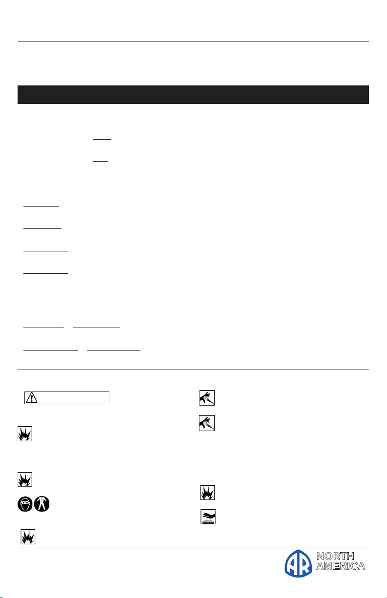
WARNINGS
Gasoline Drive Pumps
The pump is designed to pump nonflammable or non-explosive fluids.
These pumps are intended to pump
clean filtered water only.
Do not operate in or around an
explosive environment.
Always wear safety glasses
or goggles and appropriate
clothing.
Do not alter the pump from the
Conversions
Gallons x 3.785412 = Liters
Gallons x 128 = Oz.
PSI x .06896 = Bar
Bar x 14.5038 = PSI
1 inches = 25.4 millimeters
Liters x .2642 = Gallons (US)
Ft. Lbs. x 1.356 = Newton Meters
Inch Lbs. x .11298 = Newton Meters
Newton Meters x .737562 = Ft. Lbs. (force)
Newton Meters x 8.85 = In. Lbs. (force)
Temperature = 1.8(C° + 17.78) = F°,.555(F°
- 32) = C°
1 U.S. Gallon of freshwater = 8.33 lbs.
1 PSI = 2.31 feet of water
1 PSI = 2.04 inches of mercury
1 Foot of water = .433 PSI
1 Foot of water = .885 inches of mercury
1 Meter of water = 3.28 feet of water
Kilograms x 2.2 = Lbs.
manufacturers design.
Do not allow children to operate
the pump.
Never point the high-pressure
discharge at a person, any part of
the body or animals.
Do not operate gasoline engines in a
confined area; always have adequate
ventilation.
Do not exceed the pump
specifications in speed or pressure.
Maximum water temperature is
140°F.
Page 5
Operating Instructions and Parts Manual RMV Series Pumps
Firs t Cho ice Wh en Qua lity Matter s
NORTH
AMERICA
Plunger Pumps
General Safety Information
(continuted)
All positive displacement plunger
pumps must have a safety relief valve
installed on the discharge side of the
pump, this valve could be either an
unloader or regulator and must be of
adequate flow and pressure for the
pump. (This pump has an unloader
already built in).
Adequate protective guards must
cover all moving parts. Perform
routine maintenance on the pump and
components.
Use only components that are rated
for the flow and pressure of the pump,
this would include hose, fittings, safety
valves, spray guns etc.
Special Features
Wet End
Manifold: Forged Brass: Strength
and no porosity - long life. Higher
hydrostatic pressures - safety. Unloader:
Integral trap pressure, fixed chemical
injector. Simple repair using a cartridge
replacement kit. Bolts: Three bolts,
6mm grade 8.8.
Valves: Ultra Form Cages: Durable,
strong, and long life. Poppets and
Spring: 303 series stainless steel. Valve
Seat: Brass with an external sealing o-
ring on both inlet and discharge valves.
Valve Caps: Machined brass for greater
strength.
Packing and Plungers: Dual seal
system. High Pressure Packing and
Low-Pressure Seals: “U” cup double
lip Buna-N for a good positive seat.
Support and Guides: Special anti-wear
plastic, 1-piece construction to assure
proper plunger alignment, maximize
packing and seal life and prevent
plunger wear and damage. Plungers:
Solid hardened stainless steel, strong
and durable.
Drive End
Bearings: Oversized ball bearing
stabilizes the crankshaft and one needle
style thrust bearing absorbs the plunger
load and assures long radial plate life.
Crankcase: Precision die-cast, with
cooling fins for maximum heat
dissipation. The housing retains the
crankshaft bearing, oil seal and rear
wobble plate bearing support washer.
Crankshaft/Wobble Plate: Precision
die-cat to assure proper stroke, duration
and alignment.
Oil Seals and O-rings: All are
constructed of Buna-N rubber. The oil
seals have stainless steel garder springs
to assure constant tension on the
sealing surface.
Oil Capacity: 2.2 oz.
Ports: Inlet Port: Is supplied with a
standard brass garden hose connection
with inlet strainer. Discharge Port:
Is supplied with 3/8”M connection.
Accessory Ports: All models have a
1/4”F port on the inlet side of the
manifold.
Extra Features
Dyno Proven: All pumps are dyno
tested to assure the theoretical design
meets the actual design.
Valve Design: Each pump series has a
valve design that optimizes its highest
efficiency.
Wet End Repair: Very simple no
special tools required.
Design: Using advanced fluid handling
design programs. Overall pump
efficiency is increased.
Page 6
Firs t Cho ice Wh en Qua lity Matter s
NORTH
AMERICA
Operating Instructions and Parts Manual RMV Series Pumps
Plunger Pumps
Installation
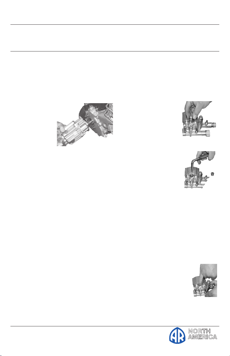
1. Install the shaft key into the keyway
and apply a light coating of antiseize on the engine shaft and key.
2. Align the two key ways and push
the pump completely onto the
engine.
3. Install all
four (4) bolts
and tighten
evenly. (See
figure 2)
4. Install the
appropriate
water inlet and discharge fittings.
5. Connect the water supply hose and
high-pressure discharge hose/spray
gun.
6. Turn on the water supply.
7. Open the spray gun to purge the
system of any air.
8. Start the engine.
9. If necessary adjust the engine speed
and unloader valve.
Figure 2
Service Pumps
Servicing the Valves
Discharge Valves:
Disassembly:
1. Remove the valve
cap (See figure 3).
2. Inspect the valve
cap O-ring for any
damage, replace if
necessary.
3. Using a needle nose
pliers remove the
valve. (See figure 4)
4. Use a small probe to
move the poppet up
and down to assure that
it is functioning properly.
5. Inspect for any debris that may be
lodged between the poppet and
seat.
Figure 3
Figure 4
6. Remove the valve seat O-ring and
inspect for any damage.
Assembly:
1. Install the valve seat
O-ring squarely into the
bottom of the manifold.
(See figure 5)
2. Insert the valve assembly
squarely into the port
pushing it into the O-ring.
Figure 5
Page 7
Operating Instructions and Parts Manual RMV Series Pumps
Firs t Cho ice Wh en Qua lity Matter s
NORTH
AMERICA
Plunger Pumps
Service Pumps (Continued)
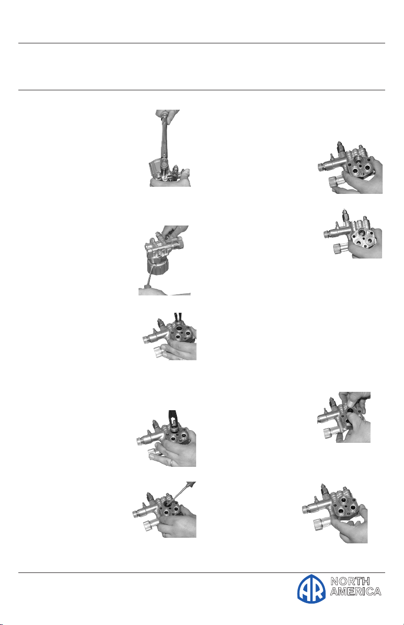
3. Install the valve cap and
torque to the proper
specifications. (See
figure 6)
Inlet Valves:
Disassembly:
1. Remove the manifold.
2. Remove low
pressure seals, insert
screwdriver under
seal lip and lift up.
(See figure 7)
3. Using a reversible
pliers, carefully remove
the packing retainers
(plunger guides). (See
figure 8)
NOTE: You do not want
to damage these so they can be
reused if not worn.
4. Remove the highpressure packing by
pulling straight out
with your finger.
(See figure 9)
5. Pull out the valve
cage/head ring
assembly, valve
poppet, spring and
O-ring.
(See figure 10)
Figure 6
Figure 7
Figure 8
Fig-
Figure 10
6. Inspect for any debris or damage.
7. Remove the valve O-ring.
Assembly:
1. Install the valve seat
O-ring squarely into
the bottom of the
manifold.
(See figure 11)
2. Insert the valve
assembly and push
squarely into the Oring. (See figure 12)
3. Install the high-pressure
packing by placing it into
the cylinder at an angle and then
pushing into place.
NOTE: The point of the “V” or
flat side of the packing is pointed
at you.
4. Lubricate the packing retainer
O-ring with a light film of oil and
install it into the cylinder.
5. Push it completely into
place.(See figure 13)
NOTE: The O-ring
will seat just inside the
manifold and you will hear a
slight pop.
6. Insert the low
pressure seal by
placing it into the
cylinder in at an
angle and pushing it into
place. (See figure 14)
Figure 11
Figure 12
Figure 13
Figure 14
Page 8
Firs t Cho ice Wh en Qua lity Matter s
NORTH
AMERICA
Operating Instructions and Parts Manual RMV Series Pumps
Plunger Pumps
Service Pumps (Continued)
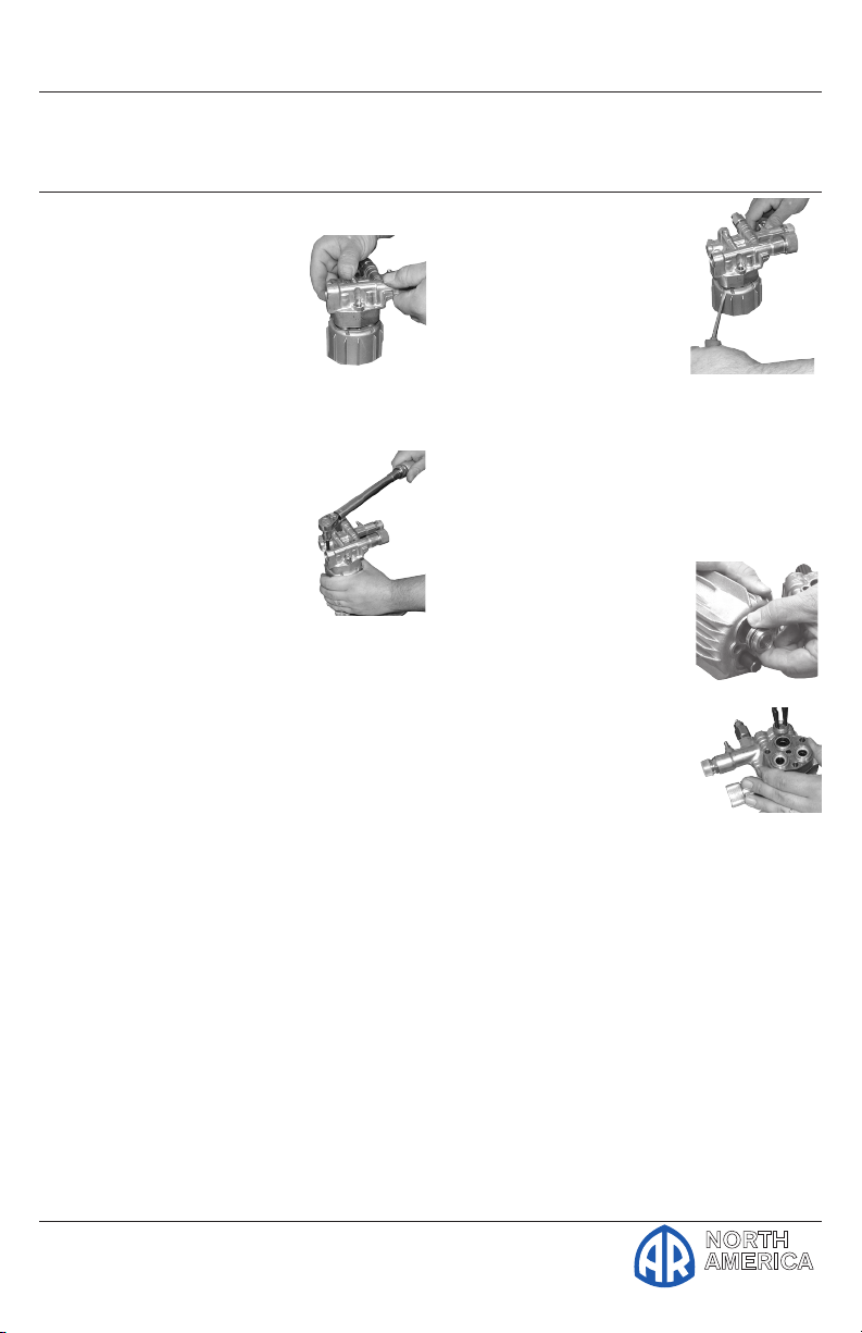
7. Put a thin coat of oil
on the plungers and
packings. (See figure
15)
8. Carefully install the
manifold and torque
the bolt to the proper
specifications. (See figure
16) (See Table C or parts
breakdown)
Valve life is dependant
on many variables. Hard
water, cavitation, corrosion,
chemicals and equipment
care. The valves are a wear item
and need periodic replacement.
Worn O-rings or damaged valves will
cause pressure loss and pulsations.
Servicing the Packings/Seals
Packings:
Disassembly:
To access the water seals for inspection or
replacement, you will first need to remove
the head of the pump.
NOTE: It is important to make note of
the order in which the components of the
packing stack are arranged and facing
during disassembly.
Figure 15
Figure 16
bar and up on the
other pry bar. (See
figure 17)
3. Lift the head up and
away from the body.
NOTE: The packing
stacks will not always
stay in the head of the pump
when it is removed. Sometimes
one or more components of the
packing stack will come out of the
head and stay on the plunger.
4. To remove any
components that
stay on the plungers
simply twist back and
forth while pulling up.
(See figure 18)
5. Remove low pressure
seals insert screwdriver
under seal lip and lift
up. (See Figure 19)
6. Remove the piston guides
from the head by using a reverse
plier (preferably rubber coated)
inserted into the center of the
piston guide.
7. Use a back and forth twisting
motion while pulling up
(clockwise and counterclockwise).
Figure 17
Figure 18
Figure 19
1. Remove the head bolts.
2. Insert small pry bars between the
head and body at opposite corners
and apply pressure down on one pry
8. Another method is to use a twoprong slide hammer puller. Insert
the prongs into the piston guide
allowing the prongs to grab under
the support ring then use the
Page 9
Operating Instructions and Parts Manual RMV Series Pumps
Firs t Cho ice Wh en Qua lity Matter s
NORTH
AMERICA
Plunger Pumps
Service Pumps (Continued)
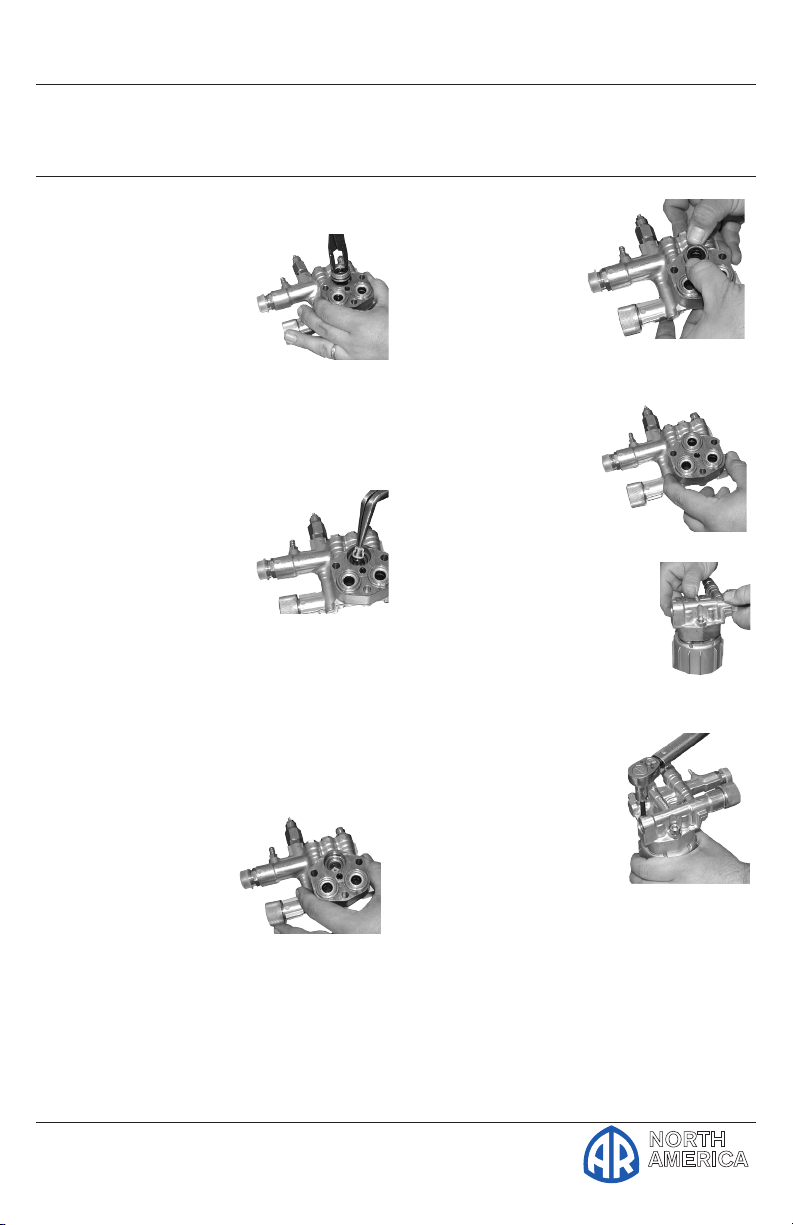
slide hammer to pull
the packing stack up
and out of the head.
(See Figure 20)
NOTE: Damage to
the piston guides and
or the seals may occur during
removal. Inspect carefully before
reusing any components of the
packing stack.
9. Remove the highpressure packing by
pulling straight out
with your finger.
(See Figure 21)
Assembly:
1. Install the high-pressure seal into
the head.
NOTE: It should fit snugly. The
packing support is part of the
valve cage.
2. Place the highpressure seal at an
angle and work it
into the cylinder.
(See Figure 22)
NOTE: The point of the
“V” or flat side of the packing is
pointed at you.
Figure 20
Figure 21
Figure 22
install it into the
cylinder. Push it
completely into
place. (See Figure
23)
NOTE: The O-ring
will seat just inside the
manifold and you will
hear a slight pop.
4. Insert the lowpressure seal by
placing it into the
cylinder in at an
angle and pushing it into
place.
(See Figure 24)
5. Put a thin coat of oil
on the plungers and
packings.
(See Figure 25)
6. Carefully install the
manifold and
torque the bolt
to the proper
specifications.
(See Figure 26)
Valve life is dependant
on many variables. Hard
water, cavitation, corrosion,
chemicals and equipment care. The
valves are a wear item and need
periodic replacement. Worn O-rings
or damaged valves will cause pressure
loss and pulsations.
Figure 23
Figure 24
Figure 25
Fig-
3. Lubricate the packing retainer
O-ring with a light film of oil and
NOTE: Water seals are wear items.
Life of the seals is dependent on
Page 10
Firs t Cho ice Wh en Qua lity Matter s
NORTH
AMERICA
Operating Instructions and Parts Manual RMV Series Pumps
Plunger Pumps
many factors. Water seals should be
replaced when water leak or a loss
of performance is noticed. Prompt
replacement of worn seals will insure
peak operating performance and
trouble free operation. The water
seals and their respective components
sometimes referred to as the packing
stack, will vary slightly between
models. But the constant between
models is that the packing stack will
consist of the following items:
Piston Guides - which usually house
the low-pressure seal
Low-Pressure Seals
Piston Guide O-rings
High-Pressure Seals
Support Rings
Torque Ratings Inch Pounds
(ft.lbs.)
Head 221 (19)
Valve Cap 221 (19)
2. Run a 50% solution of a RV or
non-toxic/biodegradable antifreeze
through the pump.
3. Flush the pump with fresh water
before the next use.
4. In freezing conditions failure to
do this may cause internal pump
damage.
5. For long periods of storage in nonfreezing areas the solution will keep
the seals and O-rings lubricated.
Oil - AR64545 - Container is 4.5 fluid
ounces. Specially formulated for the
demands of the 5XA48 pump. See
parts breakdown.
NOTE: No other oil is factory approved
for this pump. Using any other oil
may result in Drive End Damage.
Winter or Long Time Storage
1. Drain all of the water out of the
pump.
Page 11
Operating Instructions and Parts Manual RMV Series Pumps
Firs t Cho ice Wh en Qua lity Matter s
NORTH
AMERICA
Troubleshooting
Plunger Pumps
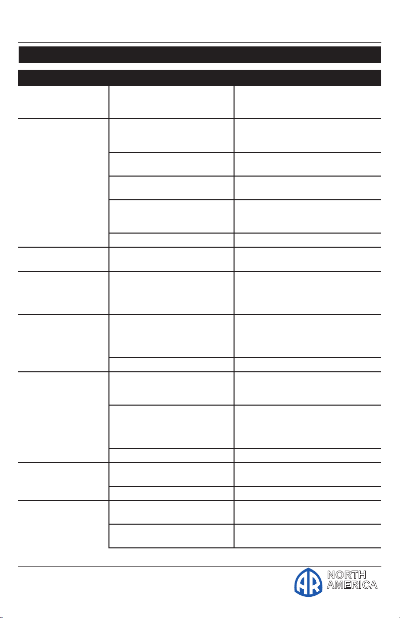
Symptom Possible Cause(s) Corrective Action
Oil leak between
crankcase and pumping section
Frequent or premature failure of the
packing
Pump runs but produces no flow
Pump fails to prime Air is trapped inside pump Disconnect discharge hose from
Pump looses prime,
chattering noise,
pressure fluctuates
Low pressure at
nozzle
Pressure gauge fluctuates
Low pressure 1 Worn nozzle 1 Replace with nozzle of proper
Worn rod oil seals Replace crankcase piston rod
1 Cracked, damaged or worn
plunger
2 Overpressure to inlet
manifold
3 Material in the fluid being
pumped
4 Excessive pressure and/or
temperature of fluid being
pumped
5 Running pump dry 5 Do not run pump without water
Pump is not primed Flood suction then restart pump
1 Air leak in suction hose or
inlet
2 Clogged suction strainer 2 Clean strainer
1 Unloader valve is by-pass-
ing
2 Incorrect or worn nozzle 2 Make sure nozzle is matched
3 Worn packing or valves 3 Replace packing or valves
1 Valves worn or blocked by
foreign bodies
2 Packing worn 2 Replace packing
2 Belt slippage 2 Tighten or replace with correct
seals
1 Replace plungers
2 Reduce inlet pressure
3 Install proper filtration on pump
inlet plumbing
4 Check pressures and fluid inlet
temperature; be sure they are
within specified range
pump. Flood suction hose,
restart pump and run pump until
all air has been evacuated
1 Remove suction line and inspect
it for a loose liner or debris
lodged in hose. Avoid all unnecessary bends. Do not kink hose
1 Make sure unloader is adjusted
property and by-pass seat is not
leaking
to the flow and pressure of the
pump. If the nozzle is worn,
replace
1 Clean or replace valves
size
belt
Page 12
Firs t Cho ice Wh en Qua lity Matter s
NORTH
AMERICA
Operating Instructions and Parts Manual RMV Series Pumps
Troubleshooting (cont.)
Plunger Pumps
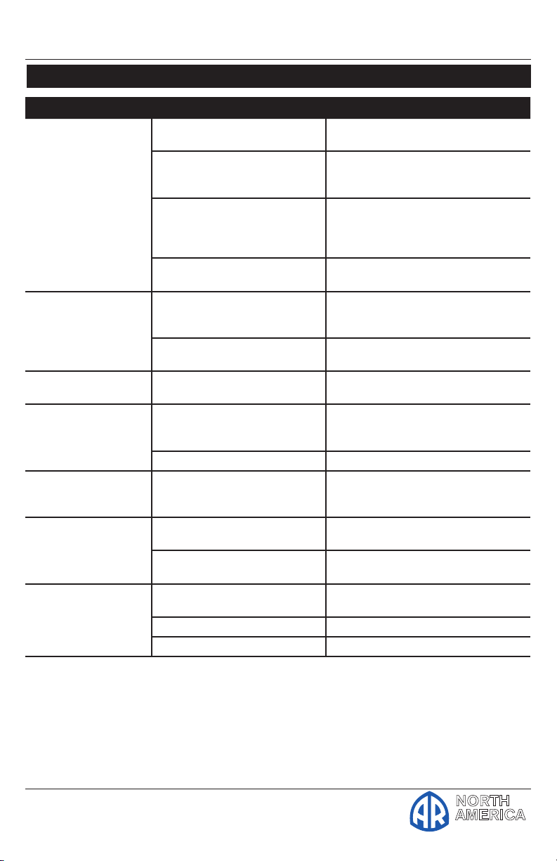
Symptom Possible Cause(s) Corrective Action
Low pressure (cont.) 3 Air leak in inlet plumbing 3 Disassemble, reseal and reas-
4 Relief valve stuck, partially
plugged or improperly
adjusted valve seat worn
5 Worn packing. Abrasive
in pumped in cavitation.
Inadequate water
6 Worn inlet, discharge valve
blocked or dirty
Pump runs extremely
rough, pressure very
low
Water leakage from
under manifold
Slight leak, oil leaking in the area of
crankshaft
Excessive play in the
end of the crankshaft
pulley
Water in crankcase 1 Humid air condensing into
Loud knocking noise
in pump
1 Inlet restrictions and/or air
leaks.
2 Stuck inlet or discharge
valve
Worn packing or cracked
plunger
1 Worn crankshaft seal or
improperly installed oil seal
o-ring
2 Bad bearing 2 Replace bearing
Worn main bearing from
excessive tension on drive
belt
water inside the crankcase
2 Worn packing and/or
cracked plunger
1 Cavitation or sucking air 1 Check water supply is turned on
2 Pulley loose on crankshaft 2 Check key and tighten set screw
3 Broken or worn bearing 3 Replace bearing
semble
4 Clean and adjust relief valve;
check for worn or dirty valve
seats
5 Install proper filter suction at
inlet manifold must be limited to
lifting less than 20 feet of water
or 8.5 psi vacuum
6 Replace inlet and discharge valve
1 Clean out foreign material
2 Replace worn valves
Install new packing or plunger
1 Remove oil seal retainer and
replace damaged 0-ring and/or
seals
Replace crankcase bearing and/or
tension drive belt
1 Change oil intervals
2 Replace packing. Replace
plunger
Page 13
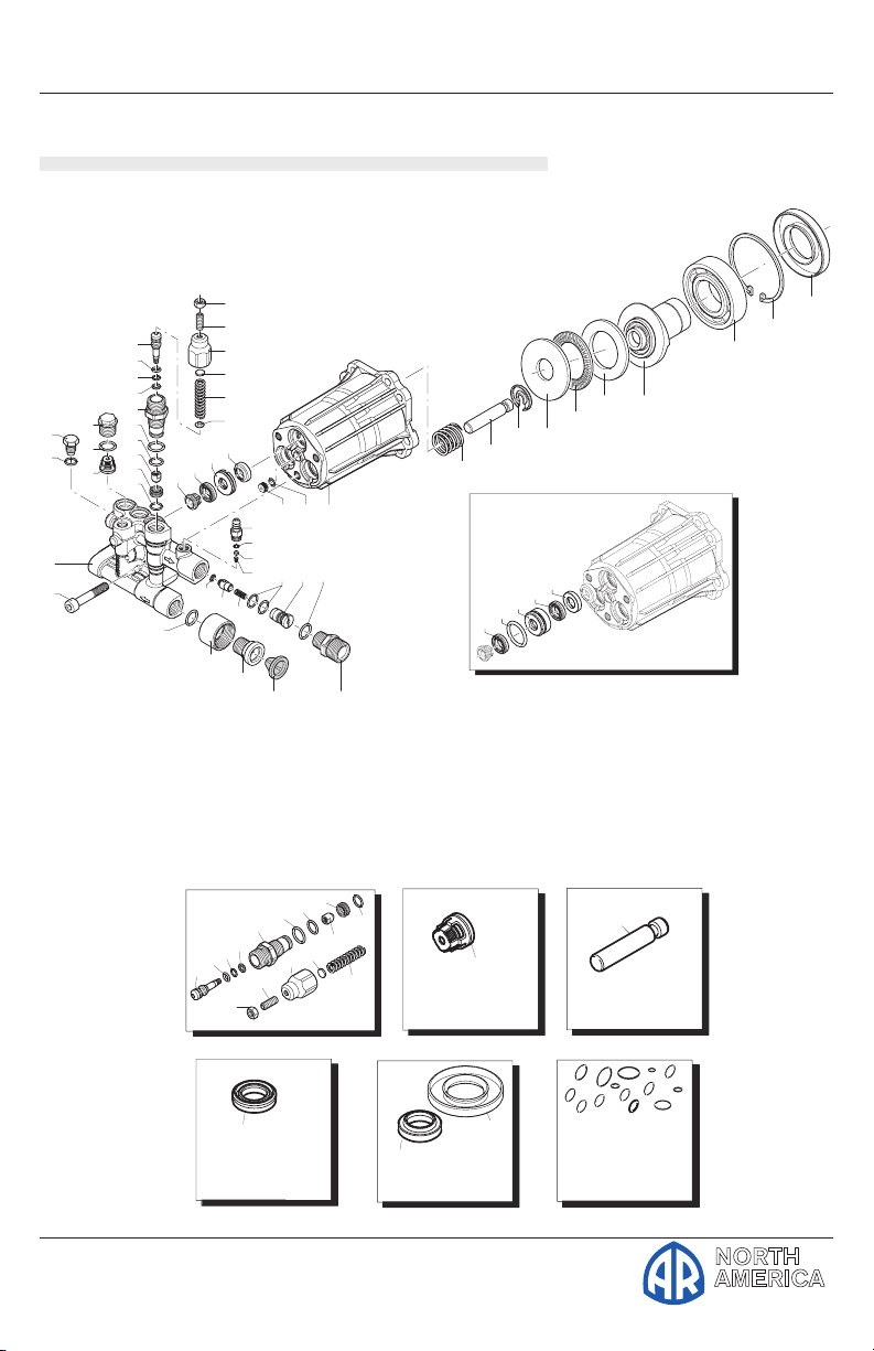
Operating Instructions and Parts Manual RMV Series Pumps
Firs t Cho ice Wh en Qua lity Matter s
NORTH
AMERICA
7
6
8
9
10
11
2
1
20
21
22
23
24
23
32 31 30
34
33
35
39
40 41 58
44
43
42
58
38
37
36
12
13
9
15
16
17
18
19
14
48
49
50 51
52
53
55
56
57
54
46
29
27
25
10
28
25
27
26
25
For
26(6)
Pistons
Kit 2234
44(3)
Valves
Kit 42123
Kit 2233
Pistons
Kit 2234
44(3)
25(3 / 6 )
Oil Seals
Kit 2236
O-Rings
Kit 2237
7(1)
8(1)
11(7)
18(1)
37(1)
40(1)
12(1)
15(1)
57
Pistons
Kit 2234
44(3)
25(3 / 6 )
Oil Seals
Kit 2236
57
26(6)
Pistons
Kit 2234
44(3)
29(3)
Water Seals
Kit 42122
Kit 2235
25(3 / 6 )
Oil Seals
Kit 2236
Valves
Kit 42123
Kit 2233
57
Pistons
Kit 2234
44(3)
Pistons
Kit 2234
44(3)
25(3 / 6 )
Oil Seals
Kit 2236
O-Rings
Kit 2237
7(1)
8(1)
11(7)
18(1)
37(1)
40(1)
12(1)
15(1)
13
Unloader
Kit 42118
9
11
15
12
16
14
22
20
18
24
23(2)
21
17
19
57
RMV
Plunger Pumps
3400 rpm
Repair Kits
Page 14
Firs t Cho ice Wh en Qua lity Matter s
NORTH
AMERICA
Operating Instructions and Parts Manual RMV Series Pumps
Pos. Part # Description Qty. Pos. Part # Description Qty.
Plunger Pumps
1 800220 Head bolt M8x45 (221 in/lbs) 3
2840860 Pump head ml 1
2 2840870 Pump head rn 1
6 2840830 Plug 1
7 600180 O-Ring Ø7.66x1.78 1
8 2840130 Plug (221 in/lbs) 3
9 740290 O-Ring Ø14x1.7 4
10 2849050 Complete valve 6
11 1470210 O-Ring Ø9x1 1
12 2840770 Seat 1
13 2840760 By-pass jet 1
14 820510 O-Ring Ø10.82x1.78 1
15 2840750 Piston guide 1
16 2760210 Ring 1
17 660190 O-Ring Ø6.07x1.78 1
18 2260100 O-Ring Ø6.02x2.62 1
19 2760400 Piston 1
20 1980300 Nut M6 1
21 392840 Grub screw M6x16 1
22 2760480 Handle insert 1
23 1980220 Plate spring 2
24 2760410 Spring 1
25 2200141 Gasket 6
26 770590 O-Ring Ø23.52x1.78 3
2840561 Bushing mr 3
2840090 Bushing ln 3
27
2840550 Bushing 3
28 2840540 Bushing 3
29 1683500 Seal 3
30 2840230 Housing 1
31 480560 O-Ring Ø6.75x1.78 1
32 2840710 Oil plug 1
33 480480 O-Ring Ø4.48x1.78 2
34 1982520 Hose nipple 1
35 1250280 Ball 1
36 1560520 Spring 1
37 1460430 O-Ring Ø4x2.5 1
38 2840350 Jet 1
39 1343580 Spring 1
40 800560 O-Ring Ø8.73x1.78 2
41 2840340 Detergent injector 1
42 2840270 Suction fitting 3/4” NH 1
43 2840390 Suction fitting 1
44 1266330 Filter 1
46 2840400 Outlet fitting 1
48 2840060 Spring 3
49 2840530 Piston 3
50 2840050 Ring 3
51 1980130 Thrust washer 1
52 1980250 Bushing 1
53 1980240 Thrust washer 1
2840900 Hollow shaft mr 1
54
2840730 Hollow shaft ln 1
55 161060 Bearing 1
56 161050 Circlip Øi72 1
57 2840310 Seal 1
58 2840890 O-Ring Ø14x2 2
AR64545 Oil 1
Oil CapaCity 2.2 Oz
Legend
Ø 12 Ø 12 Ø 12 Ø 12
For m For l For r For n
RMV2G20 RMV2.5G20 RMV2G23B RMV2.5G23B
For For
RMV2G25 RMV2.5G25
Page 15
Operating Instructions and Parts Manual RMV Series Pumps
Firs t Cho ice Wh en Qua lity Matter s
NORTH
AMERICA
Plunger Pumps
Torque Specifications in/lbs:(ft/lbs)
Oil Manifold Piston Rear Side Valve Connecting
Capacity (Head) Nut Cover Cover Cap Rods
RMV 2.2 221(19) N/A 221/(19) N/A 221(19) N/A
Limited Warranty
Annovi Reverberi (A.R.) Cam Shaft Plunger Pumps are warranted for a period of
five years and Axial Radial Pumps are warranted for a period of one year to the
original purchaser. Electric Pressure Washers are warranted for a period of one
year to the original purchaser. This is from the date shipped from factory or U.S.
Warehouse. AR, ArrowLine and GF accessories are warranted for a period of
90 days.
Warranty covers manufacturing defects or workmanship; that may develop
under normal use and service in a manner up to the directions and usage
recommended by the manufacturer.
Warranty does not apply to misuse or when pump or accessory is altered or used
in excess of recommended speeds, pressures, temperatures or handling fluids
not suitable for pump or accessory material construction. Warranty does not
apply to normal wear (such as but not limited to: seals/packings, valves, plungers
and sealing o-rings), freight damage, freezing damage or damage caused by
parts or accessories not supplied by AR North America, Inc.
Liability of manufacturer for warranty is limited to repair or replacement of parts
only at the option of the manufacturer when such products are found to be of
original defect or workmanship at the time it was shipped from factory. This
warranty is in lieu of all other warranties, expressed or implied, including any
warranty of merchantability and of any and all other obligations or liabilities on
the part of the manufacturers or equipment.
Warranty returns
Items returned for warranty consideration must have a Returned
Merchandise Authorization (RMA) number. All unauthorized returns
will be refused and shipped back to sender. Please fax requests to:
763-398-2009 or e-mail to [email protected].
 Loading...