

Page 1
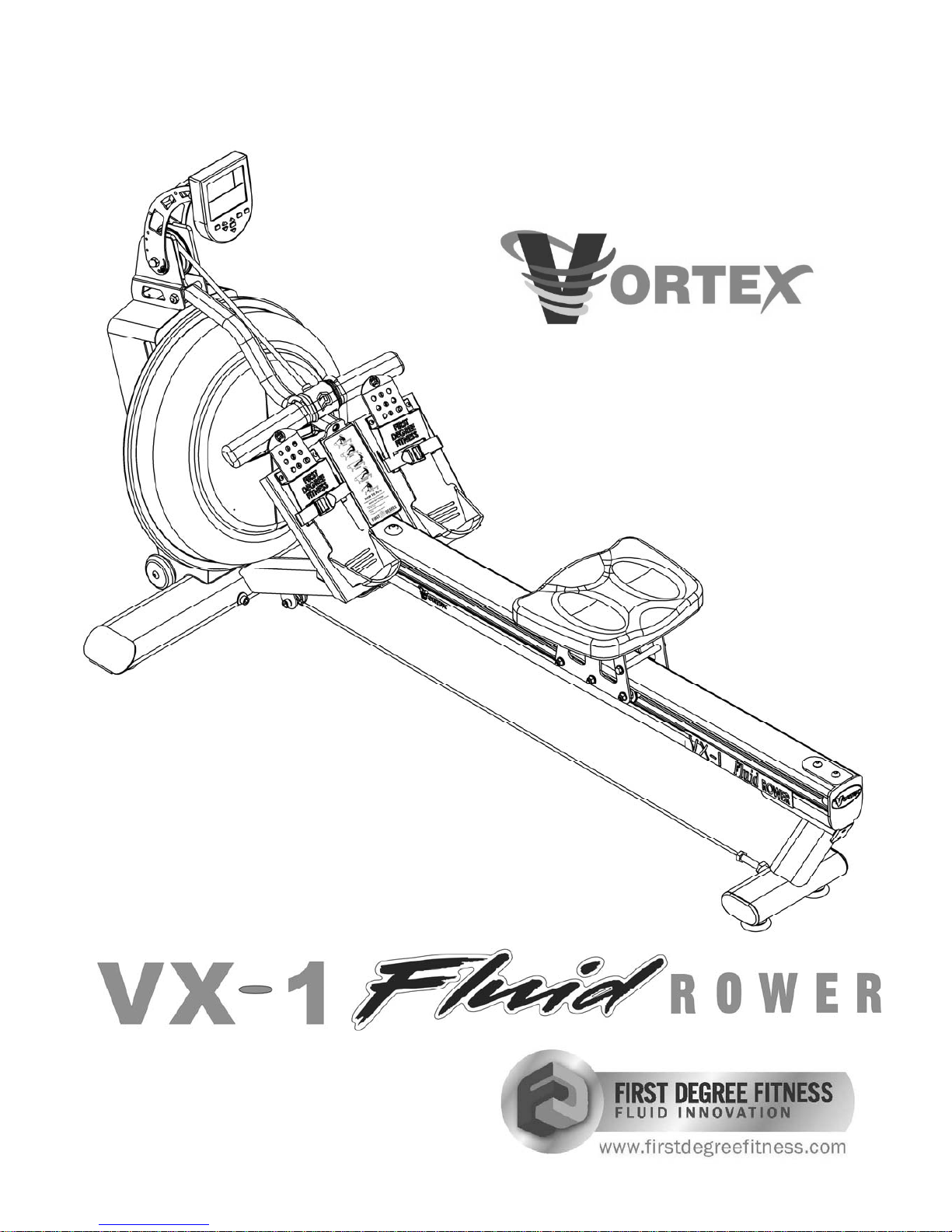
Owners Manual
Page 2
2
Contents
1. Contents of VX-1 Pack.
2. VX-1 Assembly Instructions.
3. Tank Filling and Water Treatment.
4. How to Row/Operational Instructions.
5. The VX-1 Computer with optional USB Function
6. Long Term Water Treatment/Basic Operation.
7. Maintenance and Maintenance Chart.
8. Troubleshooting Guide.
9. Changing the Bungee Cord.
10. Parts List.
11. Warranty.
Training with the VX-1
1. As with any piece of fitness equipment, consult a physician before
beginning your VX-1 Rower exercise program.
2. Follow instructions provided in this manual for correct foot position
and basic rowing techniques.
3. For more detailed rowing techniques, please refer to our
international website at www.firstdegreefitness.com
CAUTION
1. The VX-1 can stand vertically for storage. When doing so, please
follow the instructions given in the basic operation section of this
manual.
CAUTION
2. Keep hands away from moving parts, as indicated by the warning
sticker on the mainframe of your machine and inside the PVC rear
cover.
Page 3
3
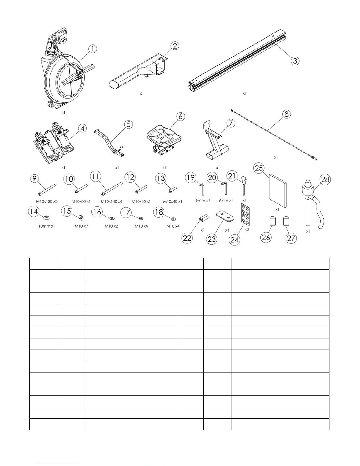
Box Contents:
Item Qty Description Item Qty Description
1 1 Upper Mainframe and Tank 15 9 Washer M10
2 1 Lower mainframe 16 2 Curved Washer M10
3 1 Seat Rail 17 4 Nut M10
4 1 Footplate 18 4 Plastic Washer M10
5 1 S-bend bar handle catch 19 1 6mm Hex Key
6 1 Rower seat 20 1 8mm Hex key
7 1 Rear leg 21 1 Multi-tool
8 1 Frame Tension Cable 22 2 AA batteries
9 3 Bolt M10 x 120 23 1 Seat Rail Bracket
10 1 Bolt M10 x 80 24 2 Chlorine tablets
11 4 Hex Head Bolt M10 x 140 25 1 Owners Manual
12 1 Bolt M10 x 65 26 1 Blue dye
13 1 Bolt M10 x 40 27 1 Touch up paint
14 1 Plastic Dome Cap 28 1 Siphon
Page 4

4
VX-1 Assembly: Attaching Upper/Lower Frame
M10x140mm bolts (2x) and 2x
curved washers. Do not tighten.
Do not attempt to stand rower until
footplate/seat rail assembly is attached.
See following page for details.
WARNING
M10x65mm bolt and washer
Tighten all three bolts.
Lower Frame
Upper Frame
Step 1: Open box and remove contents. Lie Upper frame on it’s back as shown here. In
the bolt pack, locate 2x M10x140mm bolts and curved washers along with 1x M10x65mm
dome head bolt and washer. Connect the Lower Frame to Upper using M10x140mm bolts
first and do not tighten before installing the third M10x70mm bolt as shown lower right.
Caution: the curved washers can damage paint if not lying flush against oval tube when
tightened. Use care when securing.
CAUTION: Align the curved
washer with curvature of frame for
a flush fit and to avoid scratching.
Page 5
5
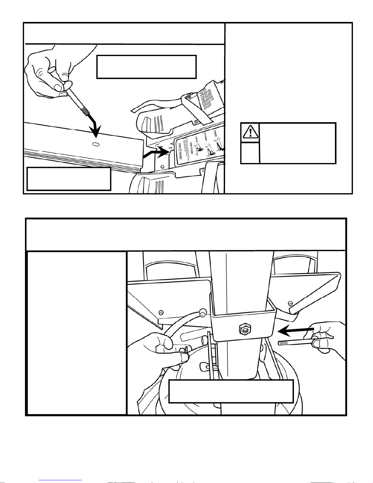
Attaching Seat Rail to Footplate
Installing Seat Rail/Footplate Assembly to Mainframe
Step 1: Locate Seat Rail/Footplate,
M10x120mm Bolt and Plastic Dome
Cap.
Insert Seat Rail into Footplate and connect the two using the M10x120mm
Dome Head Bolt and Dome cap.
Tighten securely.
Step 1: With frame assembly
on it’s back, align and install
the Seat Rail/Footplate Assembly to the Mainframe using
M10x140mm Hex Bolts, standard washers and Nylock nuts.
Caution: The Seat Rail/
Footplate Assembly is heavy
and should be installed with
the rower standing in the
vertical position for maximum
safety. Two people are required for this portion of the
assembly.
The following portion
of assembly will
require two people.
M10x120mm Dome head bolt
and Plastic Dome Cap
S
e
a
t
R
a
i
l
M10x140mm Hex Bolt (2x) M10 Washers (4x) and M10 Nylock Nuts (2x).
Insert Seat Rail into
footplate as shown
Page 6
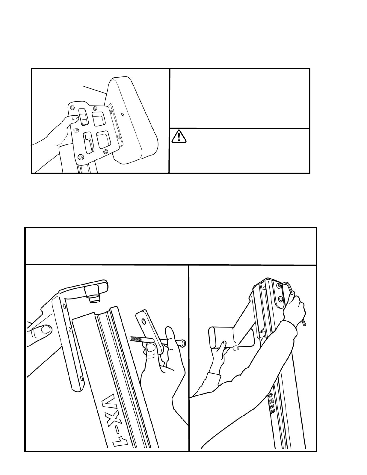
6
Seat indentation
Installing the Seat and Rear Leg
Step 1: First, insert the Rower seat onto
the seat rail keeping seat indentation
rearward.
Tip: Keep Rower upright during this section
of assembly.
Next, using the Rear Leg, Seat Rail Bracket, 2 x 120mm Dome Head Bolts/Washers, install the
Rear Leg to the Seat Rail and secure as shown below. Note: Keep oval portion of Seat Rail
Bracket forward as shown.
CAUTION: Rower seat is heavy. Use
care and grasp tightly when guiding
down the seat rail. Keep fingers clear
of seat rail channels.
Page 7
7
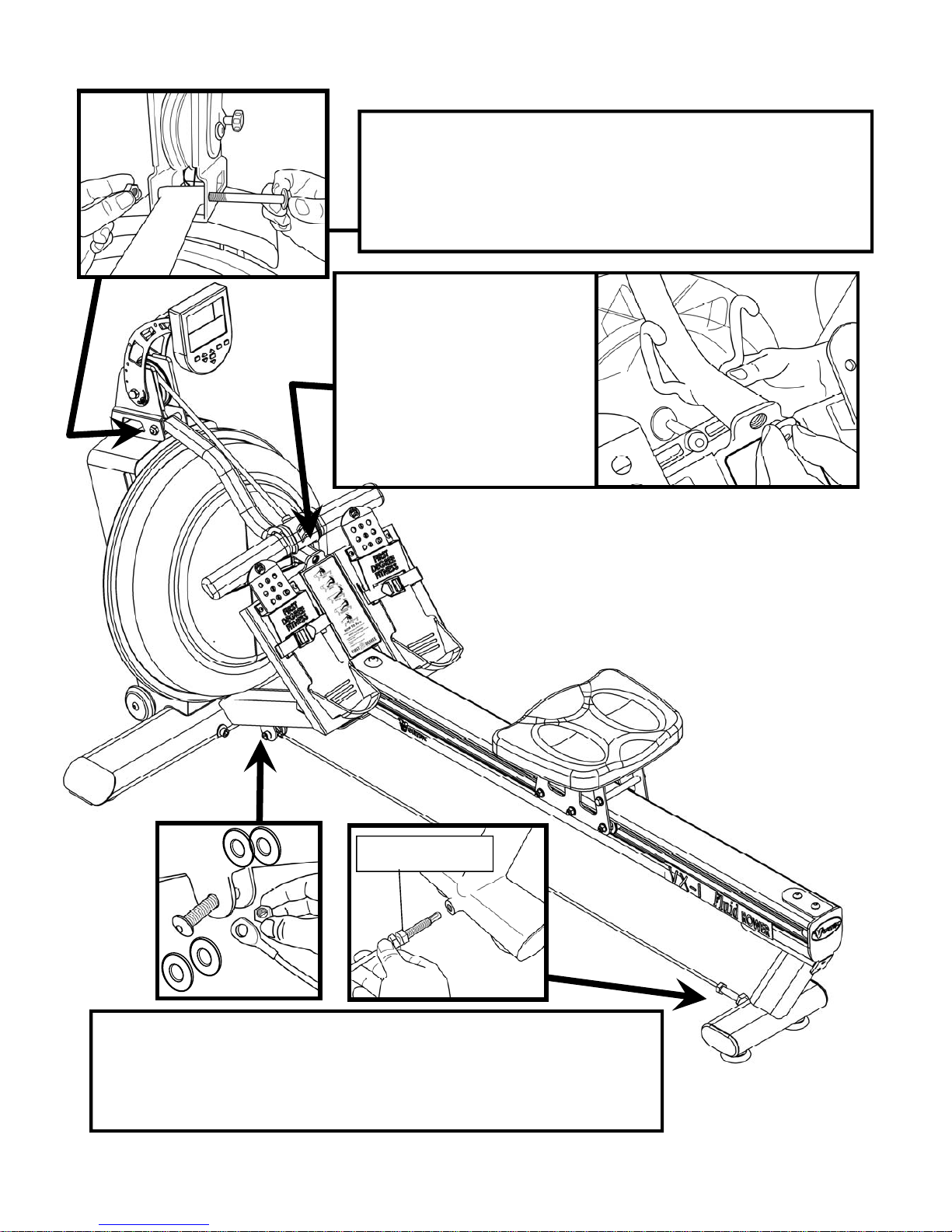
Step 3. Align the Frame Tension Cable eyelet with the Bracket on
lower frame and install with M10x40mm Bolt, 4x M10 plastic washers
(2 either side of eyelet) and Nylock Nut. Then, thread the rear portion
into the Rear Leg as shown. Tension until taut and then secure with
Retaining Nut.
Carefully lower the rower t o its normal operating position to
complete assembly with S-bend installation and Frame
Tension Cable.
Step 1. Install rear of S-bend onto the Upper Frame using
M10x80 mm Bolt, M10 Nylock Nut and 2 x M10 Washers.
Step 2. Attach the S-bend to
the Footplate as shown. Tilt the
upper frame slightly forward to
align in the proper position.
Note the M10x15mm S-bend
bolt with washer is pre-installed
on the S-bend for your
convenience.
Installing the S-bend and Frame Tension Cable
Retaining Nut.
Page 8
8
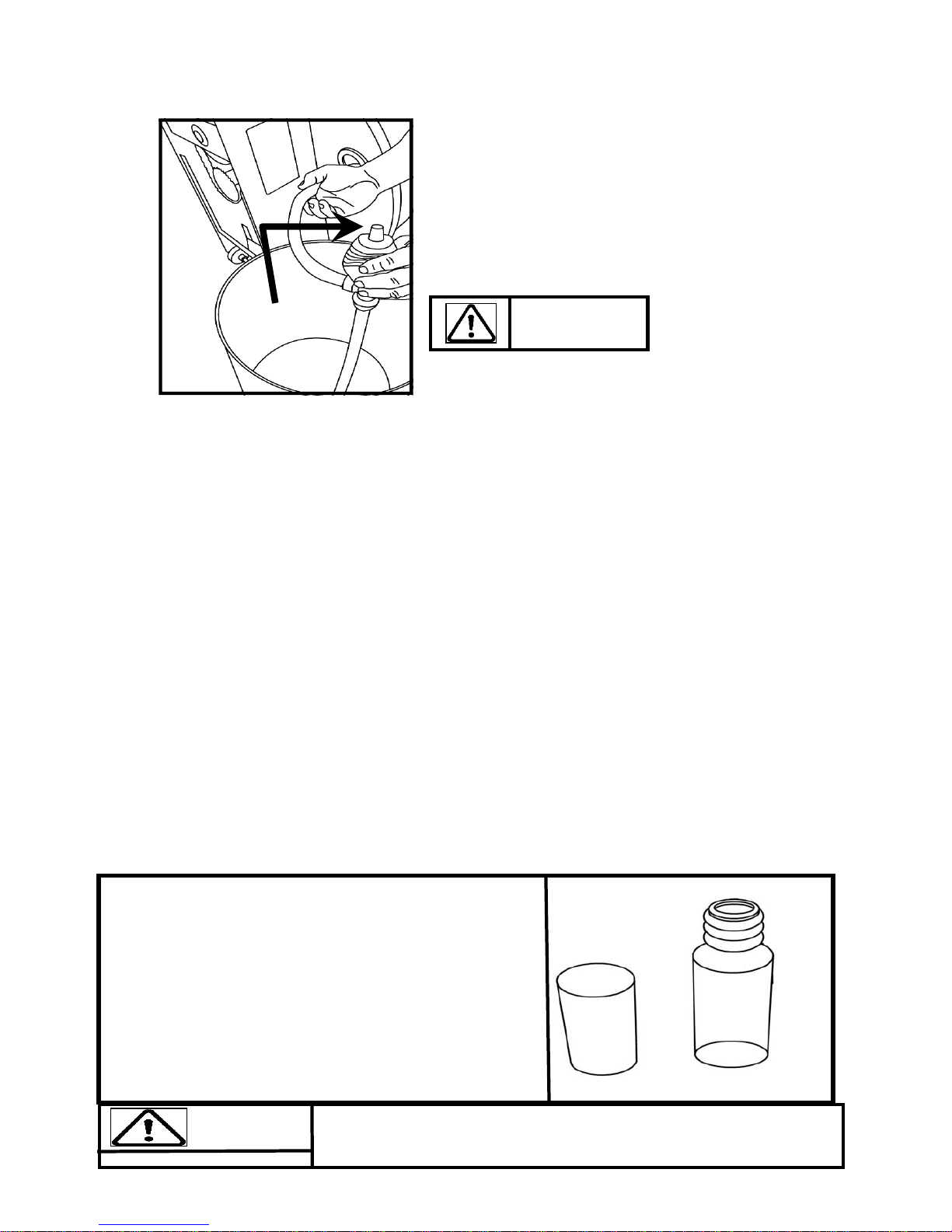
Fill tank as shown left. Use the Yellow plug only for
filling.
Fill with adjuster handle at level 16 only.
Once filling is complete, use a coin or large blade screw-
driver to tighten tank plug into place.
Siphon valve
Tank Filling and Water Treatment
1. Filling requires a large bucket (not supplied) and the Fluid Rower siphon (included). Filling will
take approximately 7.6 liters of water.
2. Unscrew the yellow plug on the tank back and insert the flexible tube into the rear of the tank
while keeping the rigid hose in the bucket. Note: The siphon tube may be impeded by one of the
impeller blades. Use the siphon only to push the impeller down slightly.
Note: Where water quality is known to be poor, FDF recommends the use of distilled water.
3. Move the adjuster handle to level 16, and begin filling. Note: The siphon valve must be closed
to allow siphoning action to occur. Tip: Placing the bucket in an elevated position will allow the
siphon to continually pump water into the tank. Do not fill past the calibration mark indicated
on the tank!
Note: Opening the siphon valve will stop the pumping action. Use this feature to avoid water spillage when nearing filling completion.
4, Once filling is complete (to the proper calibration level as indicated on the tank), follow water
treatment schedule as shown.
Note: the lower tank plug is permanently sealed.
Warning:
Do not for any reason insert fingers into the tank!
Water Treatment Procedures:
1. Add one Chlorine tablet.
2. Wait a minimum of 72 hours. Then add very small
amount of blue dye and check for desired color. Impor-
tant! Do not add blue dye for at least 72 hours following Chlorine treatment. The blue dye adds visual
appeal as well as cutting down the amount of light affecting the tank water, thus extending the amount of
time between water treatments.
Blue dye
Use a drop cloth under the tank both when filling the tank and adding blue dye to avoid staining floor or carpet
Caution:
Page 9
9
How Often?
Begin with 5 minute training sessions once a day and aim for around 2:30 to 2:45 for 500m time. Row at
a pace that keeps the water circulating continuously between strokes.
Progress a few minutes more each day until you are comfortable with 30-45 minutes training time 3 or 4
times a week.
This will provide aerobic endurance benefits, muscle toning and sufficient calorie burning to form part of
a weight loss program.
CAUTION
Always consult a doctor before beginning an exercise program.
Stop immediately if you feel faint or dizzy.
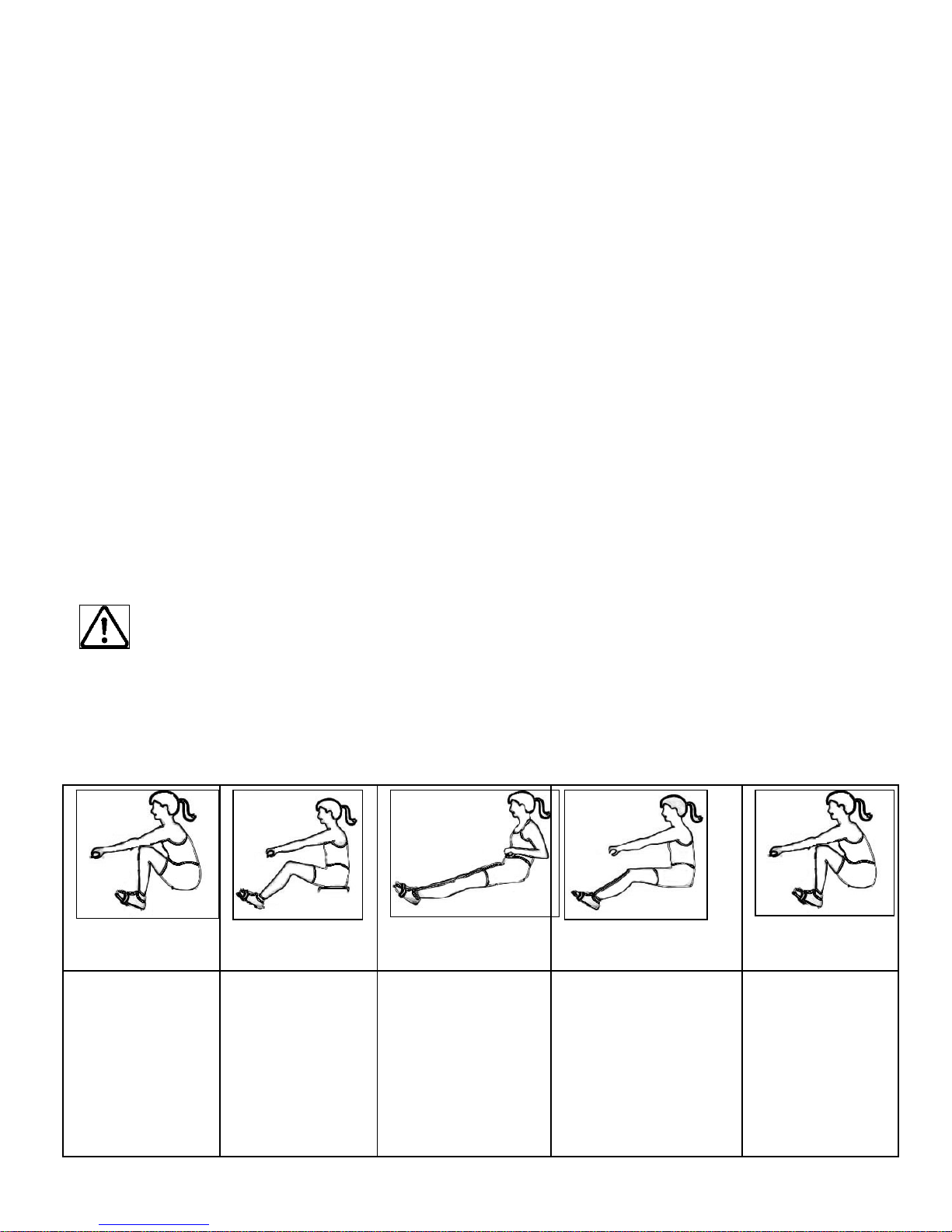
Catch
Comfortably forward with straight
back and arms.
Drive
Push with the
legs while arms
remain straight.
Finish
Pull through with
arms and legs rocking slightly back on
your pelvis.
Recovery
Upper body tips forward over your pelvis
and move forward.
Catch
Catch and begin
again.
How to Row?
1. Begin the stroke comfortably forward and push strongly back with your legs while keeping your arms
and back straight.
2. Begin to pull your arms back as they pass over your knees and continue the stroke through to completion rocking slightly back over your pelvis.
3. Return to the starting position and repeat.
4. For further details regarding rowing technique, please refer to our international website at
www.firstdegreefitness.com
Page 10
10
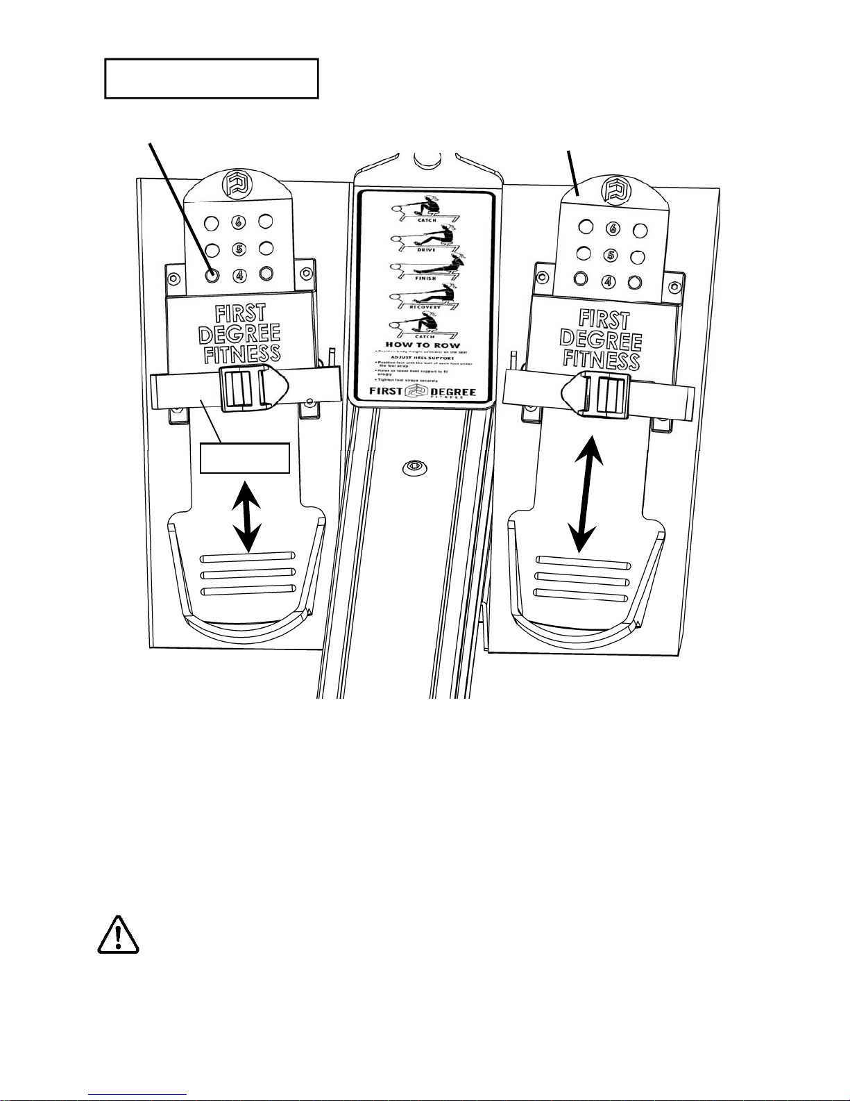
Slider Footplate
To adjust, lift and slide
Mounting pegs
Footstrap
The Slider Footplate is designed to fit a wide range of foot sizes, and is very simple to
use.
To adjust, lift the top of the sliding portion of the footplate and slide up or down. The
numbers 1-6 represent a guideline from which the proper length can be determined.
Secure the plate onto the mounting pegs and push down firmly to lock into position.
Tighten the Footstraps securely and begin your workout.
WARNING: Never operate this rower without feet properly secured in Footstraps,
or without the sliding portion of the Slider Footplate locked into position!
Page 11
11
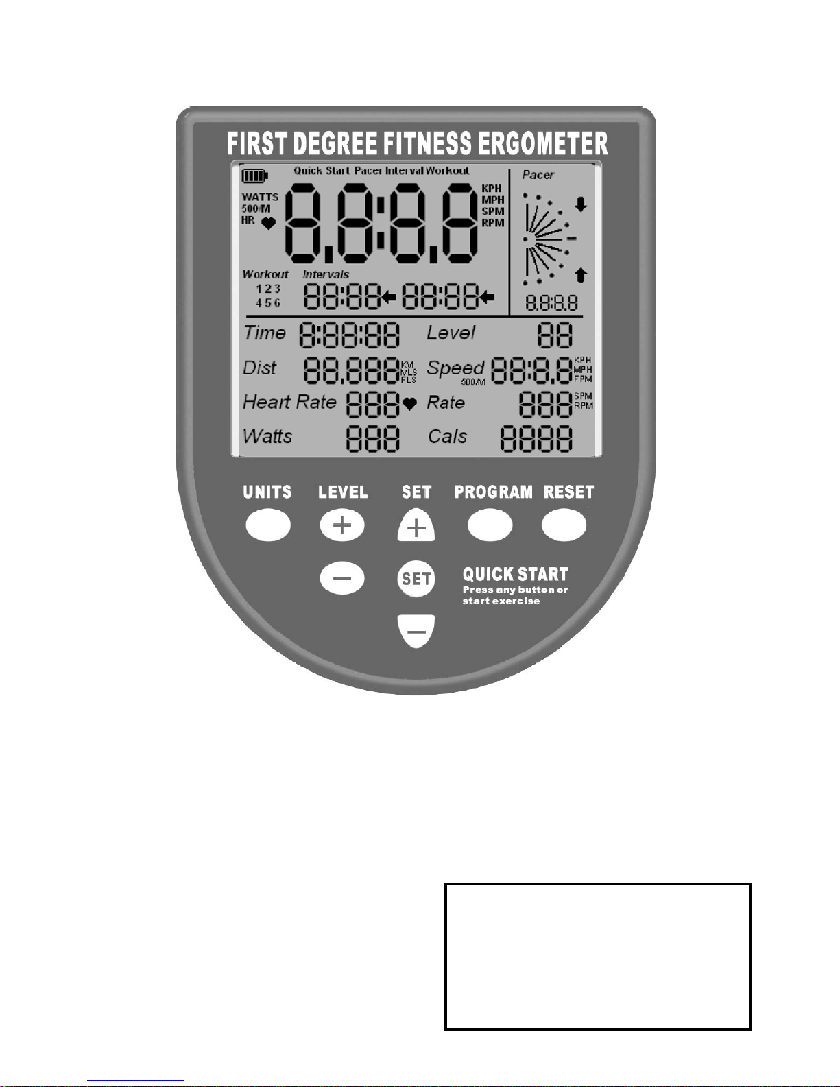
The VX-1 Rower Ergometer
UNITS: Displays WATTS, SPM, HR, 500/m
LEVEL: Adjustable from 1-16. Match LEVEL number with resistance level on the Fluid tank.
SET: Changes Time, Distance parameters
PROGRAM: Clears current exercise program
Note: For complete operational
instructions, please refer to the
computer manual, which is
included with your VX-1 Series
rower.
RESET: Clears data
Quick start: Provides instant workout information. Just start training to activate. You can
choose to change UNITS displayed
Page 12

12
The USB connectivity now built in to all new models of FDF Console and IPM allow you
to enhance your exercise experience by connecting to your home PC or Laptop. Using
FDF's own sample applications you can exercise while enjoying your favorite movies.
NetAthlon 2 XF for Rowers lets you race with other Internet connected rowers in a Virtual
Reality 3D environment or train solo.
1. Download and Install the USB Device Driver (CDM2xxxx_Setup.exe for 32 and 64 bit
Windows 7/Vista/XP) from the FDF Website.
2. Download and Install the Sample USB Applications from the FDF Website
(www.firstdegreefitness.com).
Download and Install NetAthlon 2 XF for Rowers from
http://www.webracing.org/downloads.htm
- The USB Connector is located on a flying lead at the rear of the IPM, along with the
Sensor and Heart Rate Monitor Connectors.
- Connect to a Laptop or PC using a standard USB cable, you may need to wait while
Windows starts the USB Device Driver.
Using the First Degree Fitness USB Interface
Description:
Setting up USB connectivity
Connecting your console
Note: Please refer to computer manual where applicable or for further information
refer to our website at www.firstdegreefitness.com
Page 13
13
Long Term Water Treatment:
Do not use any water treatment other than the tablets supplied with this machine. For
replacement tablets, contact your local First Degree Fitness distributor.
Water treatment schedules for the VX-1 will vary according to the fluid tanks exposure to
sunlight, but expect 8-12 months near a bright, sunlit window and 2 years or more for a darker
location. At the point of finding the water slightly cloudy, add a Chlorine tablet. Remember to
wait 72 hours following the chlorine tablet before adding the blue dye as the Chlorine tablet is
extremely concentrated.
Long Term Water Treatment and Basic Operation
Dyneema Cable Drive:
The Dyneema Cable Drive system allows for simplicity, smoothness and unparalleled performance. The unique properties of Dyneema make it extremely useful in harsh environments, such
as sailing, climbing, fishing lines, body armor, etc. It is quite literally stronger than steel. The
6mm Dyneema cable used on the VX-1 is rated in excess of 1,000kg.
Note: If the Dyneema cable is twisted excessively, the rowing stroke will feel lumpy. Use the
rower handle to untwist the cable to its normal operating position.
Light fraying is normal. The Dyneema may have a slight “fuzzy” appearance after a period of
use. Dyneema is extremely abrasion resistant and to some degree self-lubricating. Expect
many years of trouble free performance.
Frame Tension Cable:
The VX-1 is fitted with a Frame Tension cable which provides improved frame rigidity. The cable
may on occasion require adjustment. For optimum performance, the cable should be taut. If the
cable becomes loose, first loosen the Retaining nut, retighten the Frame Tension cable and then
secure the Retaining nut.
Resistance:
The level of resistance is determined by the level indicator located on
the front of the tank. Level one indicates lightest resistance, level
sixteen represents heaviest resistance. Allow three to four strokes
after adjusting resistance handle to allow the desired resistance level
to be reached.
Vertical Storage: The VX-1 can easily be stored in a vertical, upright position. For safety,
choose a suitable location, such as a corner of a room. It is recommended that something soft
(such as carpet or a small towel) be placed under the upper rear of the unit to avoid marring
either the paint or Perspex cover.
It is recommended that a drop cloth be used under the fluid
tank whenever the tank is open for water treatment
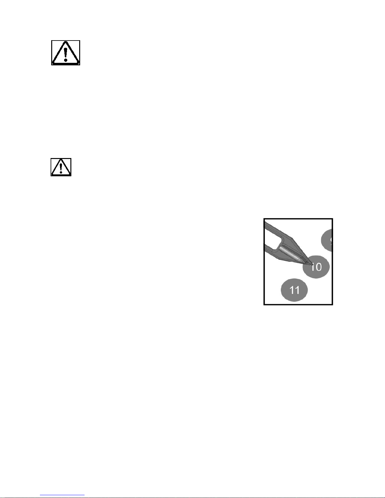
CAUTION:
Important: Do not fill past the calibration mark as indicated
on the tank level sticker or water spillage can occur. See
tank filling/water treatment page for details.
CAUTION:
Page 14

14
Item Timeframe Instructions Notes
Seat and Seat
Rails.
Weekly. Wipe Seat Rails with lint free
cloth. Spray Seat Rails with a
light coat of silicone spray.
Frame. Weekly. Wipe down with lint free cloth.
Tank and Water
Treatment.
12 months to 2 years. Follow instructions as specified
in the “Water Treatment” section
of this manual.
Bungee Cord. Check every hundred
hours for correct tension
and for signs of wear.
The Bungee Cord should last for
many years. If a Bungee Cord
change is required, please follow the instructions provided in
the “Changing the Bungee
Cord” section of this manual.
Dyneema Cable. Check monthly for signs of
twisting, excess fraying or
other signs of premature
wear. Note that a light
“fuzz” is perfectly normal
for Dyneema Cable and
will not affect performance
or longevity in any way.
The Dyneema Cable should
rarely require changing, but
should the need arise, please
follow the instructions provided
in the “Changing the Dyneema
Cable” section of in the service
section of the First Degree Fitness website at
www.firstdegreefitness.com
Frame Tension
Cable
Check regularly for proper
tension.
Tighten until taut. See Basic
Operation page for details
Maintenance chart.
Page 15

15
Fault Probable Cause Solution
Water changes color or
becomes cloudy.
Rower is in direct sunlight
or has not had water
treatment.
Change rower location to reduce direct
exposure to sunlight. Add water treatment and blue dye or change tank water
as directed in the water treatment section of this manual.
Rowing stroke return too
light.
Bungee not under enough
tension.
Open rear Perspex cover, cut bungee
tie wrap . Tighten by small increments
using the bungee tie off tab point and
test tension by allowing the rowing handle to return to its furthest point forward
while still having some slight tension.
Note light fraying of the bungee cord is
normal.
Rower rocks from side to
side when sitting on floor
Front/Rear frame levelers
need adjusting
Adjust the front two frame levelers or
rear leg levelers until stability is
reached. Note: It is normal for the
lower rear leveler to rest slightly off the
floor.
Front of rower lifts slightly
during vigorous rowing.
Lower rear frame leveler
too high.
Check to see that frame tensioning bolt
is tightened properly. Lower rear frame
leveler should be approx 5mm off the
ground.
Computer screen illuminates, but does not register when rowing.
Loose or failed connection/Sensor gap too wide
(see erratic computer display).
Check that the computer lead is connected properly. If connected properly
check sensor gap. Contact your local
service center if this fails to address the
problem.
Rowing stroke feels
lumpy, not smooth.
Dyneema Cable is
twisted .
You can untwist the Dyneema Cable by
simply pulling the rowing handle to the
end and turning the rowing handle to
untwist the cable.
Note: Light fraying is normal.
The VX-1 computer does
not illuminate after battery
installation.
Batteries installed incorrectly or need replacing.
Reinstall batteries in correct position
and try again. If the LCD screen fails to
illuminate, try rotating the batteries
slightly in the computer. If this fails,
contact your local service center.
The VX-1 computer display is erratic while displaying SPM and
500meter times.
Gap between sensor and
magnetic ring is too wide.
Adjust sensor location using rear sliding
adjustment located inside rear Perspex
cover.
Excessive frame flex
during hard rowing.
Frame Tension Cable is
too loose
Loosen frame tension cable Retaining
nut and tighten cable until taut.
Troubleshooting Guide
Page 16
16
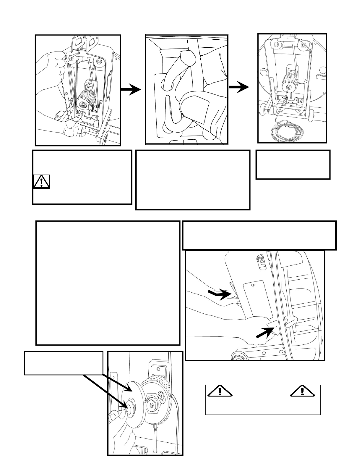
Replacing the VX-1 Bungee Shock Cord
Step 2. Move the rowing handle
from the S-Bend handle catch to a
point where it is resting on top of the
tank . This helps line up the Bungee
Cord hole for easier removal/
replacement. Detach Bungee Cord
from lower rear attachment point.
Step 3. Unwrap the
Bungee Cord from all
of the Bungee Pulleys.
Step 1. Remove the Perspex
cover from rear of upper frame.
Disconnect sensor lead
before removing cover
completely.
Step 4. Next, remove the magnetic ring. To
loosen the Rear Mainshaft Bolt holding the
magnetic ring in place, it is necessary to keep
the mainshaft and impeller assembly from turning with the bolt. Open the yellow tank plug
and insert a wrench wrapped in a lint free cloth
(to protect the electroplating finish on the
blades) to catch the impeller blade and allow
the Rear Mainshaft Bolt to be loosened as
shown below right with a 6mm Allen key.
Caution: Do not allow a dissimilar metal to
directly contact the impeller blade. Premature
rusting could occur . Cover any tool inserted
the tanks with a lint free cloth and keep fingers
clear.
Capture impeller blade using tool covered with a
lint free cloth and a 6mm Allen key to remove
Rear Mainshaft Bolt as show right
Rear Mainshaft Bolt and
Magnetic Ring
WARNING
Do not insert fingers into tank!
Page 17
17
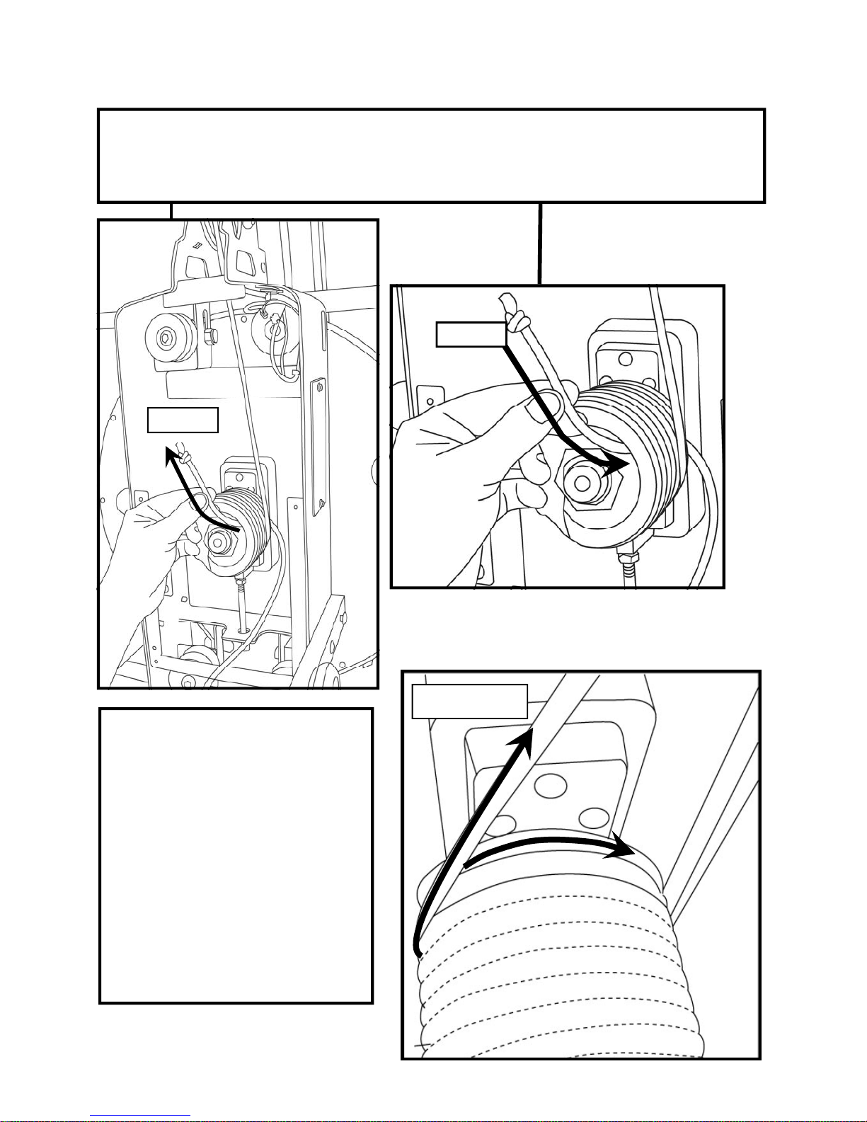
Replacing the VX-1 Bungee Shock Cord
Step 6. Once the Bungee Cord is in
position, make two wraps on the
Rope/Bungee Pulley in a clockwise
direction, making sure the Bungee
Cord tracks in the proper grooves.
Make sure the Bungee is wrapped
behind the Dyneema Cable. Once
the Bungee has reached the position
shown below, you may begin to rewrap the Bungee around the Bungee
Pulleys, starting with the upper-right
rear Pulley.
Re-Wrapping
Remove
Replace
Step 5. After removing the magnetic ring, the Bungee Cord will be accessible. Pull through
the Rope/Bungee Pulley and remove. Note that the rower handle should be resting on top of
the tank (as shown in step 2) for the bungee hole to line up. Thread new Bungee Cord
through and pull until knotted end is held securely in the slot.
Page 18
18
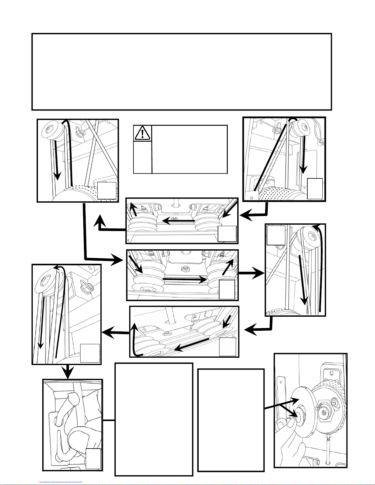
Replacing the VX-1 Bungee Shock Cord
Bungee wrapping in order:
1. Rope/Bungee Pulley to upper rear right Bungee Pulley.
2. Upper rear right to lower rear right and left rear Pulleys.
3. Lower left rear to upper left rear Pulley.
4. Upper left rear to lower middle left and right Pulleys.
5. Middle right Pulley to upper right front Pulley.
6. Upper front right Pulley to lower front right and left Pulleys.
7. Lower left front Pulley to upper left front Pulley.
8. Upper left front Pulley to tie off point.
Hint: Keep a slight
tension on the Bungee
Cord when threading
through the Bungee
Pulleys
.
2
1
3
4
6
5
Finish the Bungee rewrap by tying off the
Bungee. You may
elect to not use a tie
wrap as the metal tab is
designed as a stand
alone attachment point.
Thread the Bungee
through to desired tension and thread the
Bungee end through
the upper hole as
shown.
8
7
Reattach the Magnetic Ring and
Rear Mainshaft
Bolt. Tighten securely.
Finally, reattach
the Sensor Lead
and replace the
Perspex rear
cover.
Page 19
19
10184
73045
10027
10047
10030
10028
10300
10044
10207
70321
70303
11409
83502
73800
50903
82084
65953
73210
74109
74109
73019
73705
70315
74101
74102
61293
10082
60146
10080
12064
71021
12060
61058
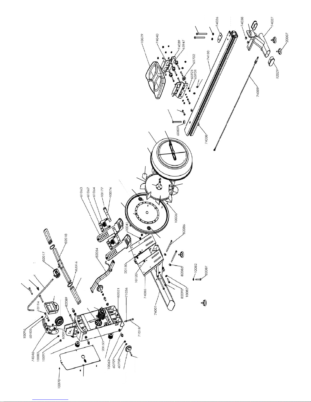
Exploded Diagram
Page 20
20
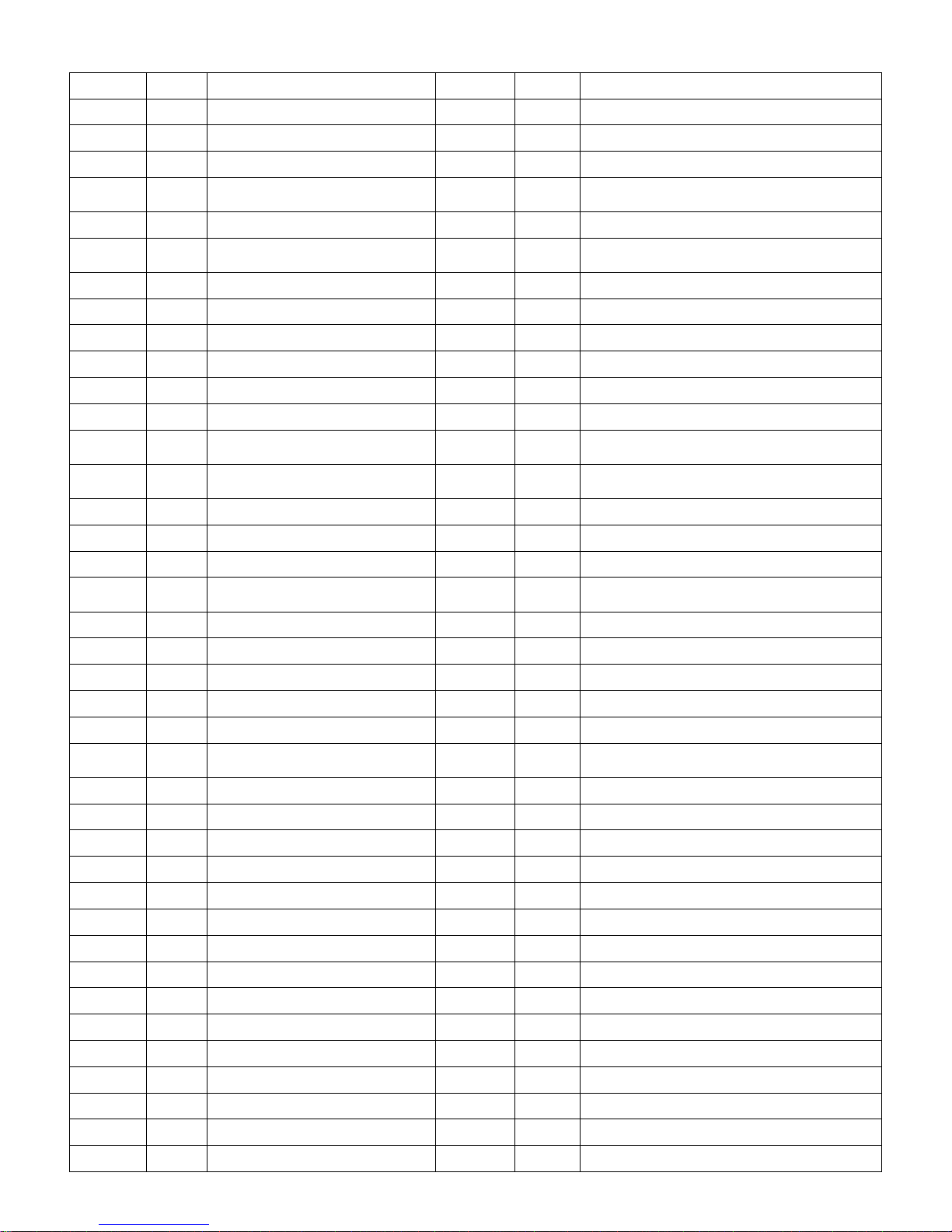
Parts list
P/N QTY Description P/N QTY Description
10027 1
Adjuster Handle Shaft 65931
3 Nut Nylock M8 -B
10028 1
Stainless 0.8mm Backing Plate
65947 1 Seat Wheel Short Spacer - B
10030 1 Adjuster PP Tank Ring 358x10 65953 2
Bolt M8x45-B
10036 16
Grub Screw M3x20 SUS for Blue
Tank Ring
70303 1 Flywheel
10041 4 Nut M10 Nylock 70315 1
Magnetic Ring & Rare Earth Magnet #70319
10044 1
Tank Black Outer Cover Ring Blue
70321
1
Tank Plug Black
10047
9 Impeller Blade
71018
1
Tank Bolt Adjuster Washer M8x110
10063 4 Bolt M12x30 71021
4
Bolt M10 x 140
10070 5 Screw M4x10 71036 1 Nut M8
10079 1 Seat LS-E28 73019
1 PVC Cover & Decal
10080
4
Bolt M6x20
73045 1 PC Tank Cover with Level Decal 16R - Blue
10082
15
Washer M10 73210
2 Transport Wheel
10096 2
Bolt M10x70
73705 1
Rope/Bungee Pulley & One Way & Needle
Bearings
10097 2
Nut Dome Head M10
73800 1
Rope Pulley 102mm & Bearings 6000ZZ
#60112
10114
2 Plastic Bushing 20x16x13x10 74001 1 Lower Frame - VX1
10120
2
Bolt M6x15
74005 1 Footplate frame - VX1
10176 2
Foot Strap & Buckle #10177
74009 1 Steel Cable
10184
1
Adjuster Handle & PU Cover P/N
10193
74026 1 Rail Bracket
10207 1 Tank Plug Yellow 74027 1 Rear Leg -VX1
10300 1 Tank Back SMC - Gray 74038 4 Rubber Bumper
11409
2
Handle Grip - Deluxe
74039 2 Spacer for Seat VX1/TRIAR
12029
2
End Cap - Rear leg 74040 2 Seat Bracket - VX1/TRIAR
12060 2 Bolt M8x60 74046 2 Computer Stalk VX1/2
20007 4
Foot Levelers M8x30 Hardened
Rubber
74100 2 Seat Rail with Decal - VX1
20150 2 Bolt M10x15 74101 1 Bolt M8x80
50903 1 IPM 74102 1 Decal - Vortex Oval
60105
1
Computer Mounting Bracket
74109 10 Bungee Pulley 50mm with Bearing
60146
4
Washer M6x16 82016 1 O-ring for Dyneema Handle
60708 4 Washer M8.5x19x1.6t
82017 1 Handle Rubber Cover
60709
2 Nut Nylock M8
82018 1 Handle Bar for Dyneema
60809 1 Plastic Dome Cap 10mm 82021 1 Upper main frame - VX-1/2
61058
4
Rubber Strip for slider footplate 82054 1 S Bend for VX
61063
2 Slider Footplate bottom 82084 1 Pop Pin
61064
2 Slider Footplate top 82085 2 Curved Washer M10
61067
4 Screw M5x15 82087
1
Bolt M10 x 65
61292
1 Bolt M10x150 82089
1
Bolt M10 x 80
61293
3 Bolt M10x130 82090
1
Bolt M10 x 45
65702
6
Seat Wheel
82091
2
Plastic Spacer for Computer stalk
65921 5 Washer 8.5x19x1.6t - B 83502 1 Dyneema with Crimped End P/N 60617
Page 21

21
VORTEX SERIES ROWERS
INTERNATIONAL WARRANTY – FULL COMMERCIAL USE
This product is designed and constructed for use in any Health Club / Fitness Studio application.
First Degree Fitness Limited warrants that the Vortex Rower (model VX-1, VX-2 & VX-3), pur-
chased from an authorised agent and in its undamaged original packaging, is free from defects in
materials and workmanship. First Degree Fitness Limited or its agent will, at their discretion, repair
or replace parts that become defective within the warranty period, subject to the specific inclusions
and exclusions below.
Metal Frame – 10 Year Limited Warranty
First Degree Fitness will repair or replace the metal Main Frame of the Rower should it fail due to
any defect in materials or workmanship within 10 years of the original purchase. Warranty does
not apply to frame coating.
Polycarbonate Tank & Seals – 3 Year Limited Warranty
First Degree Fitness will repair or replace the polycarbonate tank or seals should they fail due to
any defect in materials or workmanship within 3 years of the original purchase.
Mechanical Components (of a non-wearing nature) – 2 Year Limited Warranty
First Degree Fitness will repair or replace any mechanical component should it fail due to any defect in materials or workmanship within 2 years of the original purchase.
All Other Components (of a wearing nature) – 2 Year Limited Warranty
First Degree Fitness will repair or replace any component should it fail due to any defect in materials or workmanship within 2 years of the original purchase.
Specific Inclusions
Bungee recoil cord, belt and pulley
Hand grips & foot straps
Polyester rowing belt / Dyneema cable
Seat
All pulleys, rollers & bearings
All rubber components
Computer & speed sensor (excluding replaceable batteries)
All drive belts
Aluminum seat rails
General Exclusions
Damage to the finish of any part of the machine
Damage due to neglect, abuse, incorrect assembly or use of the machine
Any charges for freight or customs clearance associated with the return or dispatch of parts
Any damage to or loss of goods during transport of any kind
Any labour cost associated with a warranty claim
General Conditions
The serial number of the machine must be correctly registered with First Degree Fitness Lim-
ited or one of its appointed distributors
First Degree Fitness Limited reserve the right to examine any part where replacement is
claimed under warranty
Warranty period applies only to the original purchaser from the date of purchase and is not
transferable
The product must be returned to your place of purchase in original packaging with transporta-
tion, insurance and associated charges paid for by you and risk of loss or damage assumed by
you
First Degree Fitness makes no other warranties except as stated here and expressly disclaims
all warranties not stated in this warranty. Neither First Degree Fitness nor its associates shall
be responsible for incidental or consequential damages
Manufacturer's warranty automatically commences upon sale of the product to end user or
upon the expiration of one (1) year from month of manufacture, whichever occurs first
 Loading...