

Page 1
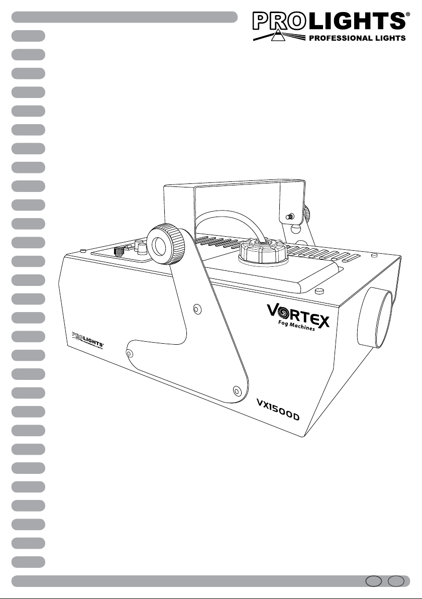
VX1500D
DMX FOG MACHINE
Manuale Utente
User Manual
I GB
Page 2

REV.001-05/11
Page 3

VX1500D
INTRODUZIONE
Vi ringraziamo per aver scelto un prodotto PROLIGHTS.
Queste macchine professionali per la produzione di fumo,
gestibili in DMX, sono ideali per medi e grandi spazi. Per
ecienza e prestazioni ottimali si raccomanda l’utilizzo dei
liquidi PROLIGHTS della serie SMOKE FLUID.
INDICE
Sicurezza
Avvertenze generali
Attenzioni e precauzioni per l’installazione
Informazioni generali
1 Descrizione e speciche tecniche
1. 1 Elementi di comando e collegamenti
1. 2 Descrizione
1. 3 Speciche tecniche
2 Funzioni e impostazioni
2. 1 Funzionamento
2. 2 Impostazioni
2. 3 Sistema di controllo wireless
2. 4 Collegamento
2. 5 Collegamenti della linea DMX
2. 6 Costruzione del terminatore DMX
2. 7 Impostazione dell’indirizzo di start
2. 8 Tabella canali DMX
2. 9 Risoluzione dei problemi
4
4
5
6
7
7
8
8
10
11
11
11
12
13
13
3
Certicato di garanzia
CONTENUTO DELL’IMBALLO:
• VX1500D
• Ricevitore KT-1 con telecomando wireless
• Prolunga XLR (5 poli)
• Manuale utente
Music & Lights S.r.l. si riserva ogni diritto di elaborazione in qualsiasi forma delle presenti istruzioni per l’uso.
La riproduzione - anche parziale - per propri scopi commerciali è vietata.
Tutte le speciche possono essere variate senza alcuna notica.
Page 4

4
ATTENZIONE! Prima di eettuare qualsiasi operazione con l’unità, leggere con attenzione
questo manuale e conservarlo accuratamente per riferimenti futuri. Contiene informazioni
importanti riguardo l’installazione, l’uso e la manutenzione dell’unità.
SICUREZZA
Avvertenze generali
• I prodotti a cui questo manuale si riferisce sono conformi alle Direttive della Comunità Europea e pertanto
recano la sigla .
• Il dispositivo funziona con pericolosa tensione di rete 230V~. Non intervenire mai al suo interno al di
fuori delle operazioni descritte nel presente manuale; esiste il pericolo di una scarica elettrica.
• È obbligatorio eettuare il collegamento ad un impianto di alimentazione dotato di un’eciente messa a
terra (apparecchio di Classe I secondo norma EN 60598-1). Si raccomanda, inoltre, di proteggere le linee
di alimentazione delle unità dai contatti indiretti e/o cortocircuiti verso massa tramite l’uso di interruttori
dierenziali opportunamente dimensionati.
• Le operazioni di collegamento alla rete di distribuzione dell’energia elettrica devono essere eettuate
da un installatore elettrico qualicato. Vericare che frequenza e tensione della rete corrispondono alla
frequenza ed alla tensione per cui l’unità è predisposta, indicate sulla targhetta dei dati elettrici.
• L’unità non per uso domestico solo per uso professionale.
• Evitare di utilizzare l’unità:
- in luoghi soggetti ad eccessiva umidità;
- in luoghi soggetti a vibrazioni, o a possibili urti;
- in luoghi a temperatura superiore ai 45°C o inferiori a 2°C.
• Evitare che nell’unità penetrino liquidi inammabili, acqua o oggetti metallici.
• Non smontare e non apportare modiche all’unità.
• Tutti gli interventi devono essere sempre e solo eettuati da personale tecnico qualicato. Rivolgersi al
più vicino centro di assistenza tecnica autorizzato.
• Se si desidera eliminare il dispositivo denitivamente, consegnarlo
per lo smaltimento ad un’istituzione locale per il riciclaggio
VX1500D
Attenzioni e precauzioni per l’installazione
• Prima di iniziare qualsiasi operazione di manutenzione o pulizia sull’unità togliere la tensione dalla rete
di alimentazione.
• Se il dispositivo dovesse trovarsi ad operare in condizioni dierenti da quelle descritte nel presente
manuale, potrebbero vericarsi dei danni; in tal caso la garanzia verrebbe a decadere. Inoltre, ogni altra
operazione potrebbe provocare cortocircuiti, incendi, scosse elettriche, rotture ect.
• È assolutamente necessario proteggere l’unità per mezzo di una fune di sicurezza. Nell’eseguire qualsiasi
intervento attenersi scrupolosamente a tutte le normative (in materia di sicurezza) vigenti nel paese di
utilizzo.
• Togliere tutto il materiale di imballo. Vicino all’ugello di erogazione non si devono trovare resti dell’imballaggio.
• Attendere il tempo di riscaldamento anché il fumo possa essere erogato.
• Posizionare l’unità orizzontalmente in un posto ventilato per evitare un surriscaldamento della stessa e
quindi uno spegnimento dovuto al fusibile termico di protezione. Evitare di ostruire l’ingresso e l’uscita
dell’aria. Tenere una distanza minima di 20 cm da altri oggetti.
• Durante il funzionamento, l’ugello di erogazione del fumo diventa molto caldo (300°C). Non toccarlo e
mantenere materiali inammabili ad una distanza di sicurezza dall’unità.
• Orientare l’unità in modo tale che il usso di fumo caldo non colpisca direttamente le persone–pericolo ustioni,
animali o cose.
• Evitare che l’unità rimanga senza liquido del fumo: la pompa potrebbe danneggiarsi.
Page 5

VX1500D
Spegnere l’unità prima di aggiungere liquido. Prestare attenzioni che non trabocchi liquido al ne di evitare
•
cortocircuiti.
• Il vericarsi di una leggera produzione di fumo anche dopo lo spegnimento della macchina è del tutto normale. A causa del fenomeno di condensazione, potrebbe formarsi vapore e/o umidità intorno
all’ugello di erogazione.
INFORMAZIONI GENERALI
Spedizioni e reclami
Le merci sono vendute “franco nostra sede” e viaggiano sempre a rischio e pericolo del distributore/cliente.
Eventuali avarie e danni dovranno essere contestati al vettore. Ogni reclamo per imballi manomessi dovrà
essere inoltrato entro 8 giorni dal ricevimento della merce.
Garanzie e resi
Il prodotto è coperto da garanzia in base alle vigenti normative. Sul sito www.musiclights.it è possibile
consultare il testo integrale delle “Condizioni Generali di Garanzia”. Si prega, dopo l’acquisto, di procedere
alla registrazione del prodotto sul sito www.musiclights.it. In alternativa il prodotto può essere registrato
compilando e inviando il modulo riportato alla ne del manuale. A tutti gli eetti la validità della garanzia è
avallata unicamente dalla presentazione del certicato di garanzia. Music & Lights constata tramite verica
sui resi la difettosità dichiarata, correlata all’appropriato utilizzo, e l’eettiva validità della garanzia; provvede quindi alla riparazione dei prodotti, declinando tuttavia ogni obbligo di risarcimento per danni diretti o
indiretti eventualmente derivanti dalla difettosità.
5
Le informazioni riportate in questo manuale sono state attentamente controllate.
Music & Lights S.r.l. non si assume, tuttavia, responsabilità derivanti da eventuali inesattezze.
Page 6
6
VX1500D
- 1 - DESCRIZIONE E SPECIFICHE TECNICHE
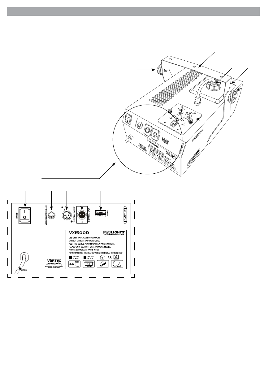
1.1 Elementi di comando e collegamenti
1
2
3
4
5
Pannello posteriore
7 8 9
106
11
1. MANOPOLA DI FISSAGGIO per la staa di
montaggio;
2. STAFFA DI MONTAGGIO;
3. TAPPO E TUBO ASPIRAZIONE;
4. SERBATOIO PORTAFLUIDO;
5. PANNELLO DI CONTROLLO per accesso e
gestione alle diverse funzioni;
6. INTERRUTTORE ON/OFF;
7. RECEIVER/ WIRELESS CONTROLLER OUT
Fig.1
8. DMX OUT (XLR a 3 poli):
1= massa, 2 = DMX -, 3 = DMX +;
9. DMX IN (XLR a 3 poli):
1 = massa, 2 = DMX -, 3 = DMX +;
10. DIP-switch [1-9], per impostare gli indirizzi
delle unità;
11. (230V~/50Hz), cavo di alimentazione con
spina Shuko.
Page 7

VX1500D
7
1.2 Descrizione
VX1500D è una macchina del fumo professionale adatta per applicazioni in ambienti di medie dimensioni
(disco, teatri, eventi indoor) dove sia necessario un eetto potente con elevata erogazione di fumo.
1.3 Speciche tecniche
Macchina per il fumo professionale da 1500W con controllo DMX.
• Funzionamento tramite caldaia per emissioni voluminose e ad alta pressione.
• Compatibile con i tradizionali liquidi per fumo a base di acqua per un’emissione di fumo secco ed omo-
geneo.
• Emissione: 20’000 cu.ft/min.
• Tempo di preriscaldamento: 8 min.
• Tecnologia plug and play: massima semplicità di utilizzo, senza necessità di connessioni o impostazioni
aggiuntive, VX1500D è già pronta all’utilizzo dall’accensione.
• Pannello di controllo e sezione comandi asportabili da pannello posteriore con lo per comando a distanza.
• Radiocomando wireless incluso.
• Interruttori dipswitch per l’indirizzamento DMX e congurazione.
• Funzionamento in modalità manuale o automatica con regolazione di intensità e intervallo di emissione.
• Funzionamento in modalità DMX con 2 canali di funzionamento.
• Controllo di temperatura elettronico contro surriscaldamento.
• Sistema di sicurezza con sensore termico elettronico contro surriscaldamento.
• Capacità serbatoio liquido: 2,5litri.
• Staa per maneggevolezza in fase di trasporto e montaggio in sospensione .
• Alimentazione: AC 220-240V 50/60 Hz.
• Connessioni DMX: XLR-3p IN, XLR-3p OUT.
• Assorbimento: 1500W.
• Peso: 9,4kg.
Modello VX1500D
Voltaggio 230 V ~ 50 Hz
Fusibile 8 A
Potenza assorbita 1500 W
Emissione 20’000 cu.ft/min
Tempo di riscaldamento 8 min
Dimensioni (LxAxP) 325x255x420mm
Peso 9,4 kg
Capacità serbatoio liquido 2,5 litri
Page 8

8
VX1500D
- 2 - FUNZIONI E IMPOSTAZIONI
2.1 Funzionamento
Le macchine per il fumo tendono a sviluppare condensa intorno all’ugello di emissione. Questo può comportare un accumulo di liquido sulla supercie sotto l’ugello. Considerare questo particolare dovendo decidere dove installare l’unità. Queste macchine possono espellere piccole quantità di fumo occasionalmente
durante le operazioni e per circa un minuto dopo lo spegnimento. Dopo alcuni minuti dall’accensione l’unità è pronta ad operare.
EVITARE CHE L’UNITÁ RIMANGA SENZA IL LIQUIDO DEL FUMO: LA POMPA POTREBBE DANNEGGIARSI!
Posizionare l’unità su un piano orizzontale;
- Svitare il tappo del serbatoio.
- Versare i liquidi Prolights della serie SMOKEFLUID. Raccogliere subito con un panno asciutto il liquido
eventualmente rovesciato per evitare che entri dentro alla macchina.
- Richiudere bene il serbatoio. Controllare che il tubo d’aspirazione arrivi no al fondo del serbatoio.
- Collegare il ricevitore KT-1 alla macchina.
- Inserire il cavo di alimentazione nella presa di corrente. Attendere alcuni minuti per il riscaldamento della
macchina.
- Fare riferimento alla sezione del manuale riservata al funzionamento tramite controllo DMX.
- Se il fumo è emesso continuamente per un lungo periodo di tempo la temperatura operativa può calare
diminuendo o bloccando l’emissione di fumo. Se ciò accade, non attivare l’emissione di fumo, attendere
brevemente che la temperatura risalga permettendone la riattivazione.
ATTENZIONE. Durante il riempimento con il liquido SMOKE FLUID la macchina non deve essere collegata
con la rete elettrica. Staccare prima la spina dalla presa.
L’unità non è protetta contro gli spruzzi d’acqua. Se del liquido nisce all’interno, non mettere in funzione la
macchina, ma rivolgersi, per un controllo, al più vicino centro di assistenza tecnica autorizzato.
2.2 Impostazioni
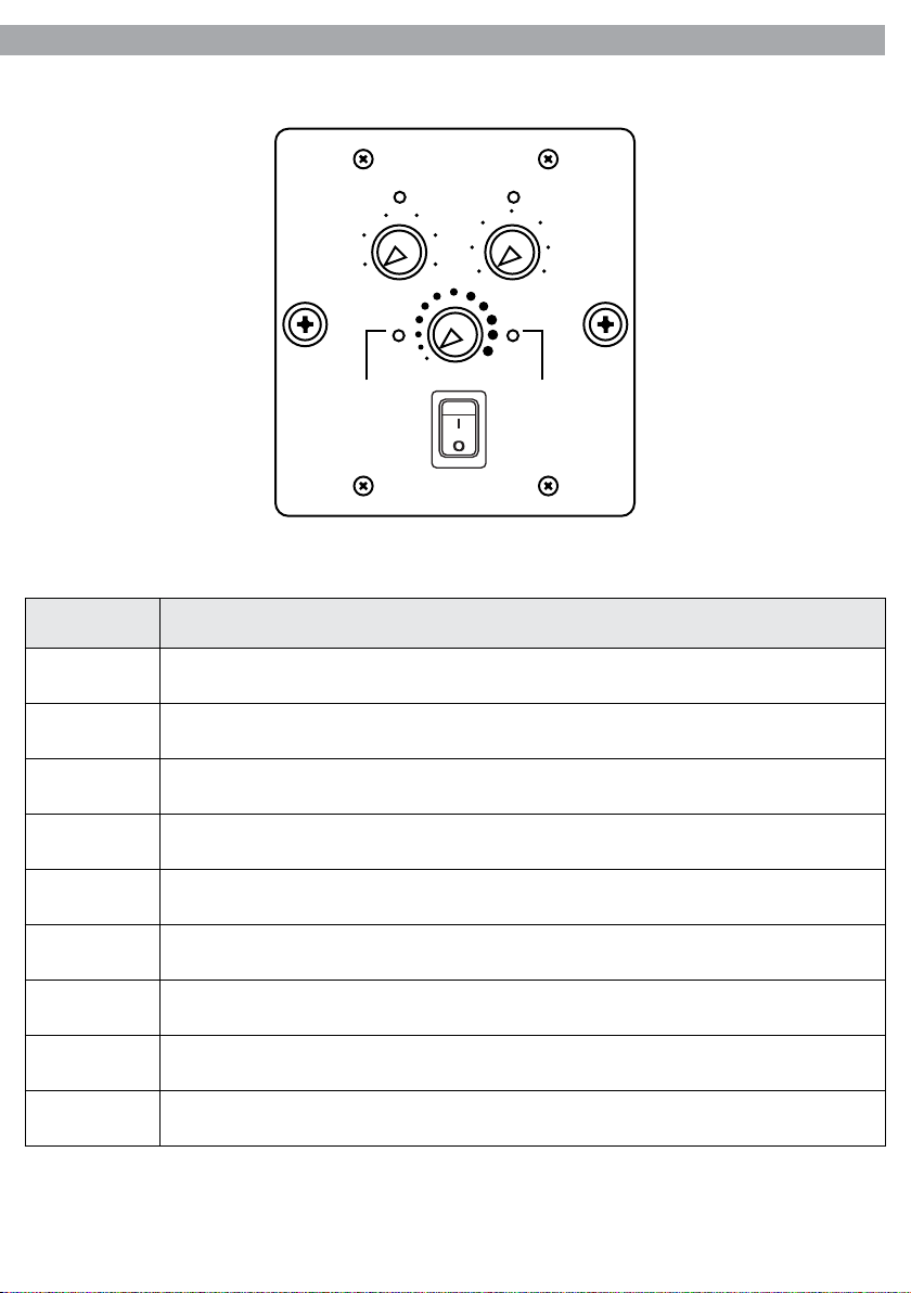
Quando il processo di preriscaldamento dell’unità è terminato, il LED READY posizionato sul pannello di
controllo si llumina di verde, indicando che l’unità è pronta all’uso. Quando la funzione TIMER è attivata,
intervenendo sulla funzione SECONDS, è possibile regolare la quantità di tempo di emissione del fumo,
mentre la funzione MINUTES permette di regolare la quantità di tempo, tra un’emissione e un’altra. Con la
funzione VOLUME si interviene sul volume di emissione. Attivando la funzione MANUAL si ottiene un’emissione continua.
NOTA: la temperatura media di utilizzo dell’unità deve essere sotto i 250°C.
ATTENZIONE: scollegare il cavo di alimentazione prima di rimuovere o sostituire il ricevitore.
Page 9
VX1500D
PANNELLO DI CONTROLLO
Power Output
9
101520
5
0
30 0
Minutes Seconds
TIMER READY
4
25
2
Volume
MANUAL
6 8
10
12
15
Fig.2
Funzione Istruzioni
MANUAL
READY
TIMER
Attivando il comando, l’interruttore si illumina di rosso, indicando il funzionamento della modalità
manuale, che consente un’emissione di fumo continua.
Quando il processo di riscaldamento dell’unità è terminato, il LED READY posizionato sul pannello di
controllo si illumina di verde, indicando che l’unità è pronta all’uso.
Quando vengono utilizzati i comandi MINUTES e SECONDS il LED TIMER si accende. Minore tempo
sarà assegnato tra un’emissione e l’altra, e maggiore sarà la sua intermittenza.
VOLUME Questo comando consente di regolare il volume di emissione desiderato.
MINUTES
SECONDS
POWER
Questo comando consente di assegnare alla macchina il tempo espresso in minuti dopo il quale la
macchina dovrà emettere fumo (max 30 min).
Questo comando consente di assegnare alla macchina il tempo espresso in secondi durante il quale
la macchina dovrà emettere fumo (max 15 sec).
Quando l’interruttore POWER della macchina è su ON, il LED POWER posizionato sul pannello di
controllo si illumina di verde, indicando che l’unità è accesa.
OUTPUT Quando la macchina emette fumo, il LED OUTPUT si illumina di verde.
INPUT Quando la macchina riceve segnale DMX, il LED INPUT si illumina di verde.
NOTA: Svitando le due viti laterali, il pannello di controllo con sezione comandi è asportabile dal pannello
posteriore con lo di lunghezza pari a 4 m (incluso) per il comando a distanza.
Page 10
10
VX1500D
2.3 Sistema di controllo wireless
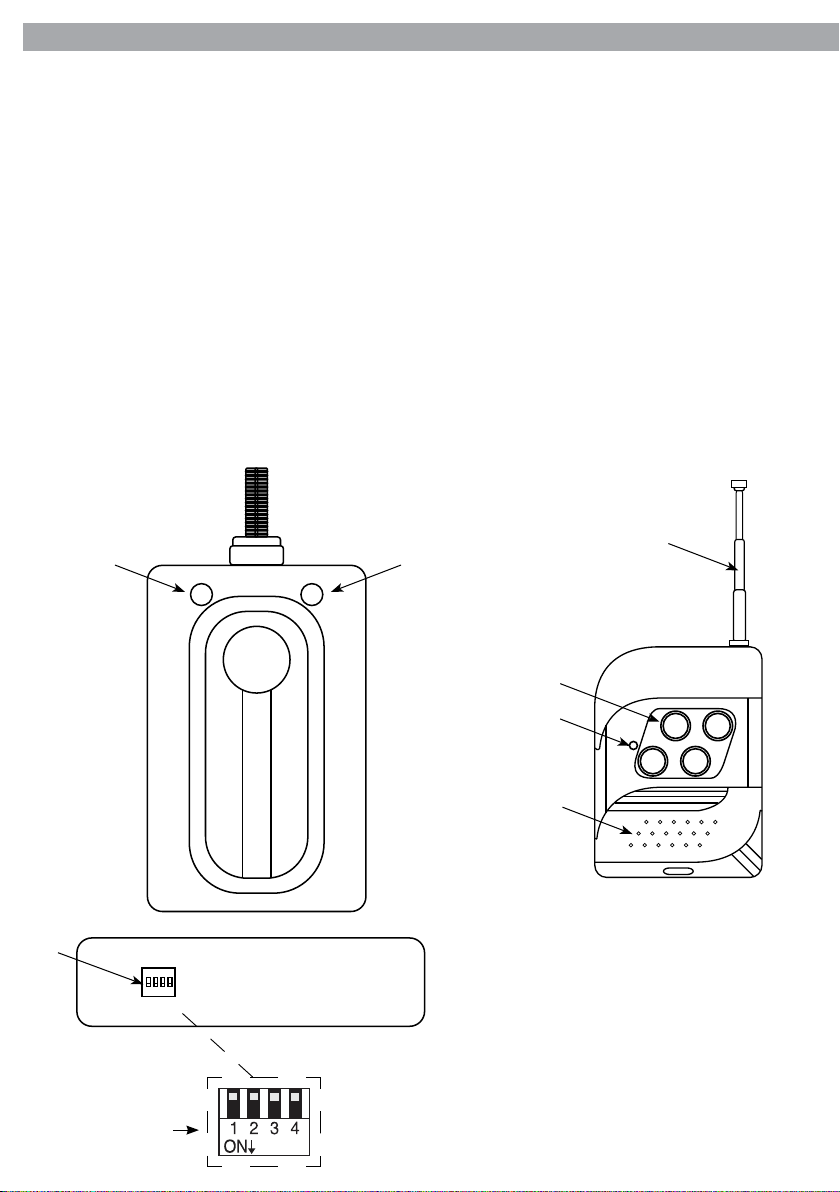
VX1500D è dotato di un sistema di controllo wireless KT-1 con relativo telecomando.
Collegare il ricevitore KT-1 all’uscita del pannello di controllo, e poi accendere la macchina. Il LED rosso
situato sul ricevitore KT-1 (13) si illuminerà segnalando che la macchina è in fase di preriscaldamento. Una
volta terminato il processo di preriscaldamento, e la macchina sarà pronta, si illuminerà il LED verde (12).
Da questo momento in poi, sarà possibile interagire con la macchina anche attraverso il telecomando wireless. Il ricevitore KT-1 è fornito di 4 dipswitch (14), situati lateralmente, i quali corrispondono, in ordine
numerico (1-4), ai tasti del telecomando wireless (16). Il LED posto sul telecomando (17) si accenderà ogni
volta che si farà pressione su uno dei tasti. Al rilascio del tasto, anche il LED si spegnerà.
Utilizzando più macchine della serie Vortex, sarà possibile assegnare un tasto specico del telecomando,
alla specica macchina, attraverso il dipswitches corrispondente.
Ad esempio, per assegnare il tasto 1 del telecomando ad una macchina, basterà posizionare su ON (verso
il basso), il dipswitch numero 1 della macchina selezionata e così via. Se si seleziona lo stesso dipswitch su
più macchine, ad esempio il numero 4, alla pressione del tasto numero 4 del telecomando, queste funzioneranno contemporaneamente.
RICEVITORE KT-1 TELECOMANDO WIRELESS
15
12
13
14
Numero switch
1 2 3 4
KT-1
WIRELESS CONTROLLER
Fig.3
16
17
2
4
1
3
18
Fig.4
12. LED VERDE;
13. LED ROSSO (sul ricevitore KT-1);
14. DIP-switch [1-4];
15. ANTENNA;
16. TASTO [1-4];
17. LED ROSSO (sul telecomando);
18. COPERCHIO TELECOMANDO.
Page 11
VX1500D
11
2.4 Collegamento
È possibile eettuare il collegamento tra più unità:
1. Collegare l’uscita DMX OUT della prima unità principale con l’ingresso DMX IN della seconda unità servendosi di un cavo XLR a 3 poli.
2. Collegare l’uscita DMX OUT della seconda unità con l’ingresso DMX IN dell’unità successiva ecc.
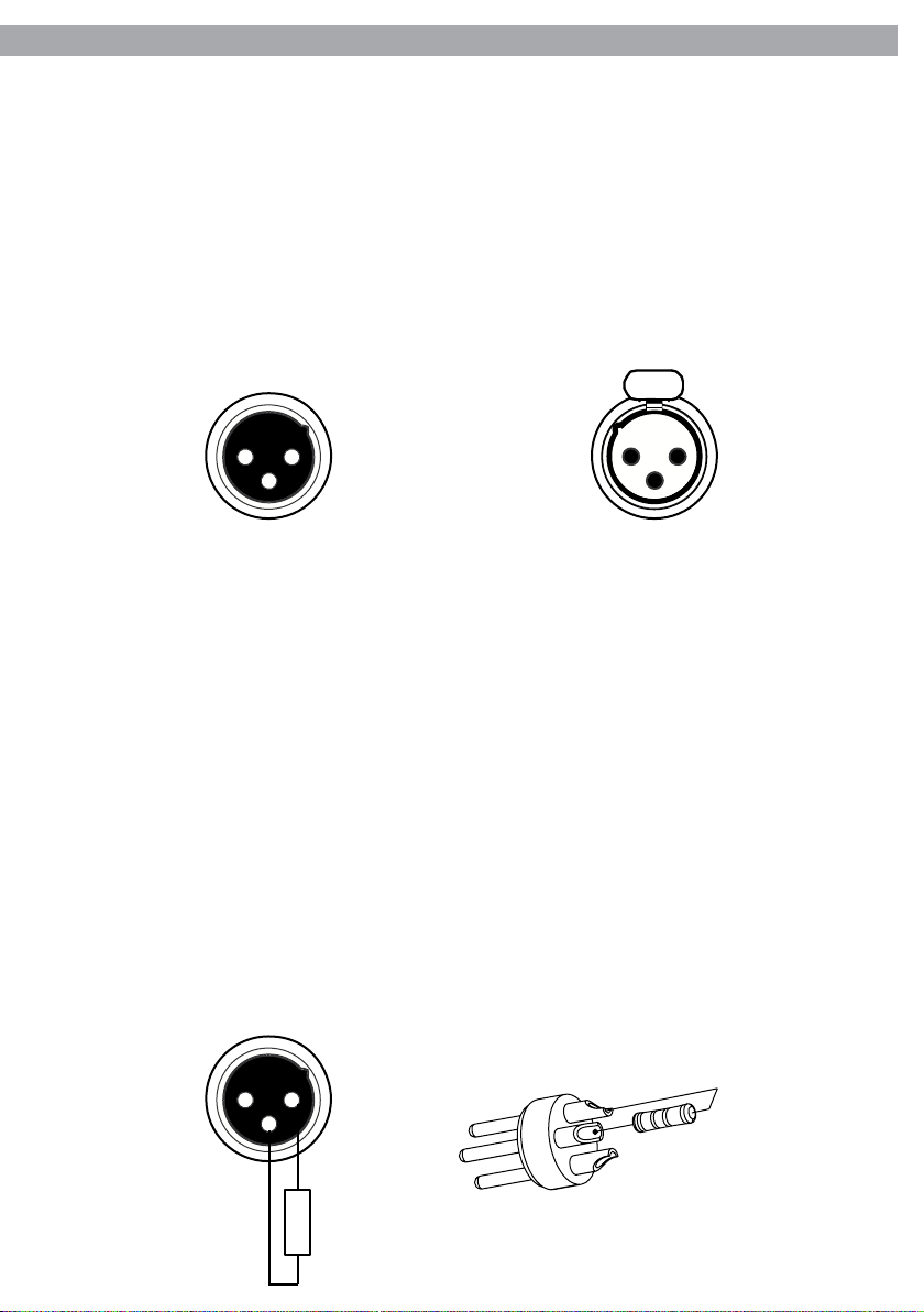
2.5 Collegamenti della linea DMX
La connessione DMX è realizzata con connettori standard XLR. Utilizzare cavi schermati, 2 poli ritorti, con
impedenza 120Ω e bassa capacità.
Per il collegamento fare riferimento allo schema di connessione riportato di seguito:
DMX - INPUT
Spina XLR
Pin1 : Massa - Schermo
3
Pin2 : - Negativo
Pin3 : + Positivo
1
21 2
3
DMX - OUTPUT
Presa XLR
ATTENZIONE
La parte schermata del cavo (calza) non deve mai essere collegata alla terra dell’impianto; ciò comporterebbe malfunzionamenti delle unità e dei controller.
Per passaggi lunghi può essere necessario l’inserimento di un amplicatore DMX.
In tal caso, è sconsigliato utilizzare nei collegamenti cavo bilanciato microfonico poiché non è in grado di
trasmettere in modo adabile i dati di controllo DMX.
• Collegare l’uscita DMX del controller con l’ingresso DMX della prima unità;
• Collegare, quindi, l’uscita DMX con l’ingresso DMX della successiva unità; l’uscita di quest’ultima con
l’ingresso di quella successiva e via dicendo nchè tutte le unità sono collegate formando una catena.
• Per installazioni in cui il cavo di segnale deve percorrere lunghe distanze è consigliato inserire sull’ultima
unità una terminazione DMX.
2.6 Costruzione del terminatore DMX
La terminazione evita la probabilità che il segnale DMX 512, una volta raggiunta la ne della linea stessa
venga riesso indietro lungo il cavo, provocando, in certe condizioni e lunghezze, la sua sovrapposizione al
segnale originale e la sua cancellazione.
La terminazione deve essere eettuata, sull’ultima unità della catena, con connettori XLR a 5 pin o 3 pin,
saldando una resistenza di 120Ω (minimo 1/4W) tra i terminali 2 e 3, così come indicato in gura.
1 2
3
120 Ω
2
3
1
Esempio:
connettore XLR a 3 pin
Page 12
12
VX1500D
2.7 Impostazione dell’indirizzo di start
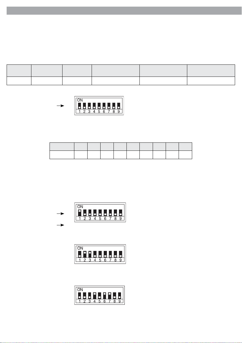
Per poter comandare la VX1500D con un’unità di controllo DMX, occorre impostare l’indirizzo di start DMX
per il primo canale DMX. Se, per esempio, sull’unità di comando è previsto l’indirizzo 33 per comandare la
funzione del primo canale DMX, si deve impostare sulla VX1500D l’indirizzo di start 33. Le altre funzioni del
pannello saranno assegnate automaticamente agli indirizzi successivi. Segue un esempio con indirizzo 33
di start:
Numero
canali DMX
2 33 33-34 35 37 39
Indirizzo di
start (esempio)
Numero switch
Indirizzo DMX
occupati
1
Prossimo indirizzo di start
possibile per unità n°1
[ ]
*
2
8
4
32
16
64
128
Prossimo indirizzo di start
possibile per unità n°2
256
Prossimo indirizzo di start
possibile per unità n°3
Gli interruttori DIP ed i valori DMX hanno la seguente relazione
Dip Switch 1 2 3 4 5 6 7 8 9
DMX Value
1 2 4 8 16 32 64 128 256
L’indirizzo di start viene impostato come numero binario per mezzo dei DIP-switch n° 1 - 9. Quindi, risulta
dall’addizione dei valori dei DIP-switches posizionati su ON.
Esempi per gli indirizzi 1, 6 e 104:
[ ]
16
32
64
*
Indirizzo di start 1: switch n° 1 su ON
128
256
Numero switch
Valore
1
2
8
4
[ ]
*
1
2
8
4
32
16
64
[ ]
*
1
2
8
4
32
16
64
128
Indirizzo di start 6: switch n° 2 e 3 su ON
128
256
Indirizzo di start 104: switch n° 4 , 6 e 7 su ON
256
Il modo più semplice è quello di partire sempre dal massimo valore possibile aggiungendo i valori minori
no a raggiungere, come somma, l’indirizzo di start.
Page 13

VX1500D
2.8 Tabella canali DMX
Canale Funzione
1 Emissione fumo
2 Tempo di intervallo emissione fumo
2.9 Risoluzione dei problemi
Questa guida elenca i problemi più frequenti e rappresenta un aiuto per tentare di risolverli. Nel caso il problema persista anche dopo aver tentato di risolverlo attraverso i seguenti step, spegnere l’unità, scollegarla
e rivolgersi a personale qualicato per un’assistenza tecnica.
L’unità è alimentata ma non viene emesso il fumo:
1. Controllare l’alimentazione di corrente. L’impianto elettrico dev’essere compatibile con il voltaggio specicato sull’unità e dev’essere dotato di una messa a terra ecace;
2. Vericare la connessione del controllo;
3. Vericare il corretto settaggio DMX;
4. Controllare lo stato del fusibile e nel caso, disconnettere l’unità dall’alimentazione elettrica e sostituire il
fusibile con uno nuovo dello stesso tipo indicato nelle speciche tecniche del presente manuale.
5. Controllare lo stato della protezione termica all’interno dell’unità. Dato che la protezione termica della
macchina del fumo è collocata sulla caldaia all’interno dell’unità, seguire attentamente le seguenti indicazioni:
- Scollegare l’alimentazione prima di rimuovere qualsiasi coperchio, poiché le parti all’interno sono in
tensione ed esiste il pericolo di una scarica elettrica.
- Per ripristinare la protezione termica, svitare le viti per rimuovere il coperchio superiore dell’unità.
- Individuare la protezione termica posizionata sulla caldaia quindi premere il pulsante per il ripristino.
- Chiudere il coperchio superiore dell’unità nuovamente con le viti.
- Connettere l’unità all’alimentazione elettrica e attendere il tempo di riscaldamento.
- Rivolgersi ad un centro di assistenza tecnica autorizzato qualora la protezione termica salti ripetutamente.
13
Page 14

Page 15

VX1500D
INTRODUCTION
Thank you for purchasing a PROLIGHTS product.
Powerful and reliable, solid and strong, these Smoke
Machines produces a large quantity of smoke, and it is ideal
for large and medium environments. For eciency and
optimal performances we recommend PROLIGHTS series
SMOKEFLUID.
TABLE OF CONTENTS
Safety
General instructions
Warnings and installation precautions
General information
1 Description and technical specications
1. 1 Operating elements and connections
1. 2 Description
1. 3 Technical specications
2 Functions and settings
2. 1 Operation
2. 2 Set-up
2. 3 Wireless remote control
2. 4 Linking
2. 5 Connection of the DMX line
2. 6 Construction of the DMX termination
2. 7 Adjusting the start address
2. 8 DMX control
2. 9 Troubleshooting
2
2
3
4
5
5
6
6
8
9
9
9
10
11
11
1
Warranty
PACKING CONTENT:
• VX1500D
• KT-1 receiver with wireless remote controller
• Extension XLR (5 poles)
• User manual
All rights reserved by Music & Lights S.r.l. No part of this instruction manual may be.
Reproduced in any form or by any means for any commercial use.
Design and specications are subject to change without notice.
Page 16

2
WARNING! Before carrying out any operations with the unit, carefully read this instruction
manual and keep it with cure for future reference. It contains important information about the
installation, usage and maintenance of the unit.
VX1500D
SAFETY
General instructions
• The products referred to in this manual conform to the European Community Directives and are therefore
marked with
• The unit is supplied with hazardous network voltage (230V~). Leave servicing to skilled personnel only.
Never make any modications on the unit not described in this instruction manual, otherwise you will
risk an electric shock.
• Connection must be made to a power supply system tted with ecient earthing (Class I appliance according to standard EN 60598-1). It is, moreover, recommended to protect the supply lines of the units
from indirect contact and/or shorting to earth by using appropriately sized residual current devices.
• The connection to the main network of electric distribution must be carried out by a qualied electrical installer. Check that the main frequency and voltage correspond to those for which the unit is designed as given
on the electrical data label.
• This unit is not for home use, only professional applications.
• Never use the xture under the following conditions:
- in places subject to excessive humidity;
- in places subject to vibrations or bumps;
- in places with a temperature of over 45°C or less than 2°C.
• Make certain that no inammable liquids, water or metal objects enter the xture.
• Do not dismantle or modify the xture.
• All work must always be carried out by qualied technical personnel. Contact the nearest sales point for
an inspection or contact the manufacturer directly.
• If the unit is to be put out of operation denitively, take it to a local
recycling plant for a disposal which is not harmful to the environment.
.
Warnings and installation precautions
• Before starting any maintenance work or cleaning the projector, cut o power from the main supply.
• If this device will be operated in any way dierent to the one described in this manual, it may suer dam-
ages and the guarantee becomes void. Furthermore, any other operation may lead to dangers like short
circuit, burns, electric shock, ect.
• Always additionally secure the unit with the safety rope. When carrying out any work, always comply
scrupulously with all the regulations (particularly regarding safety) currently in force in the country in
which the xture’s being used.
• Remove all the packaging material. Make sure that there are no packaging remnants near the fog output
nozzle.
• Wait for the warm-up time so that the fog may be emitted.
• Install the unit horizontally in a well ventilated place to avoid overheating and therefore a shutdown due
to thermal fuse protection. Avoid blocking air intakes and outputs. Keep a minimum distance of 20 cm
to any other objects.
• During operation the fog output nozzle will become very hot (300 °C). Never touch it and keep any inammable material at a safe distance from the xture.
• The fog stream is hot; position the unit in a way that the fog stream will not directly hit anyone – there is
risk of burning!, animals or property.
• Avoid that unit remains without smoke uid, the unit may be damaged.
Page 17

VX1500D
• Turn o the power before adding uid and operate carefully to avoid that the uid overows causing a
short circuit.
• Due to condensation, vapour or moisture might gather around the nozzle of the smoke machine. There
might be some smoke eject from on the smoke machine during operation and even after shut down.
GENERAL INFORMATION
Shipments and claims
The goods are sold “ex works” and always travel at the risk and danger of the distributor. Eventual damage
will have to be claimed to the freight forwarder. Any claim for broken packs will have to be forwarded within
8 days from the reception of the goods.
Warranty and returns
The guarantee covers the xture in compliance with existing regulations. You can nd the full version of the
“General Guarantee Conditions” on our web site www.musiclights.it. Please remember to register the piece
of equipment soon after you purchase it, logging on www.musiclights.it. The product can be also registered
lling in and sending the form available on your guarantee certicate. For all purposes, the validity of the
guarantee is endorsed solely on presentation of the guarantee certicate. Music & Lights will verify the validity of the claim through examination of the defect in relation to proper use and the actual validity of the
guarantee. Music & Lights will eventually provide replacement or repair of the products declining, however,
any obligation of compensation for direct or indirect damage resulting from faultiness.
3
The information provided in this manual has been carefully checked.
However Music & Lights S.r.l. is not responsible for any possible inaccuracy.
Page 18
4
VX1500D
- 1 - DESCRIPTION AND TECHNICAL SPECIFICATIONS
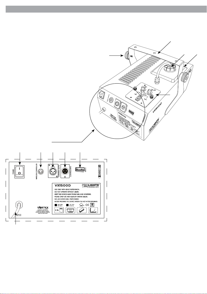
1.1 Operating elements and connections
1
2
3
4
5
Rear panel
7 8 9
106
11
1. LOCKING KNOB for the mounting bracket;
2. MOUNTING BRACKET;
3. LID SMOKE FLUID CONTAINER and
ASPIRATION TUBE;
4. SMOKE FLUID CONTAINER;
5. CONTROL PANEL;
6. POWER ON\OFF;
Fig.1
7. RECEIVER/ WIRELESS CONTROLLER OUT
8. DMX OUT (3-pole XLR):
1= ground, 2 = DMX -, 3 = DMX +;
9. DMX IN (3-pole XLR):
1= ground, 2 = DMX -, 3 = DMX +;
10. DIP-switch [1-9], or xing the unit’s addresses;
11. (230V~/50Hz), main cable with Shuko plug.
Page 19

VX1500D
5
1.2 Description
New VX1500D features low power consumption and silent operations combined with a large production of
dense smoke for better visual lighting eects. Perfect for use in any large venue. PROLIGHTS® Series SMOKE
FLUIDs are warmly recommended for the best performances and eciency.
1.3 Technical specications
1500W professional DMX fog machine.
• VX1500D is a professional Fog machine, suitable for large size environments as live, arenas, outdoor
events where a powerful ambient eect with great fogging volume is required.
• Functioning based on internal heater for high pressure and voluminous fog emission.
• Compatible with traditional water based fog liquid for dry and homogeneous fog.
• Fog output: 20’000 cu.ft/min.
• First heat-up time: 8 min.
• Plug and play technology: VX1500D is ready to work when connected with no need of additional set-
tings or connection.
• Control panel can be taken out to be used as wire-remote controller.
• Wireless controller is included.
• Dipswitches for DMX addressing and settings.
• Manual and Auto mode functioning with volume and interval regulation.
• 2 Channels DMX mode.
• Security system against clogging or pump failures.
• Electronic thermal sensor against over-heating failures.
• Ergonomic hanging bracket for an easy transportation.
• Liquid tank capacity: 2,5 lt.
• Power supply: AC 220-240V 50/60 Hz.
• DMX connection: XLR-3p IN, XLR-3p OUT.
• Power consumption: 1500W.
• Weight: 9,4kg.
Model VX1500D
Voltage 230 V ~ 50 Hz
Fuse 8 A
Electrical Input 1500 W
Output power 20’000 cu.ft/min
Preheating time 8 min
Dimensions (WxHxD) 325x255x420mm
Weight 9,4 kg
Liquid tank capacity 2,5 liter
Page 20

6
VX1500D
- 2 - FUNCTIONS AND SETTINGS
2.1 Operation
Note that fog machines develop condensation around the output nozzle. This may result in moisture accumulation on the surface below the output nozzle. Consider this condensation when installing the unit. All
fog machines may sputter small amounts of fog occasionally during operation and for a minute or so after
being turned o. The led lights upon the fog machine after being plugged in properly. After a few minutes
of warm-up time, the fog machine will be in “ready to fog” condition.
NOTE: the LED on the bottom of the tank indicates the fog uid level; when it ashes, the uid level is low
and requires rell, the pump stops simultaneously. Simply rell the tank, the pump will function again.
ADD PROLIGHTS FLUID IN TIME IF THE SMOKE MACHINE KEEPS RUNNING WHEN IT HAS RUN OUT OF
FLUID. ITS PUMP WILL BE DAMAGED!
Place the unit on a horizontal surface;
- Unscrew the tank cap.
- Fill up the fog uid container (SMOKEFLUID series). If any uid is spilt, wipe it o immediately with a dry
cloth. It must not get inside the unit.
- Tightly close the tank. Make sure that the suction hose will reach the bottom of the tank.
- Connect the wireless control KT-1 to the socket inside the housing.
- Plug main power cord from the fog machine into the appropriate power supply socket. Wait a few minutes for heating element to heat up.
- When the heating process is completed the fog machine is ready for use.
- Refer to the section of the manual “Set-up”.
- If fog is emitted continuously for a long time, the heating element temperature may drop, shutting o
fog production. If so, please do not activate fog emission. Wait briey. When the heating element temperature rises, fog emissions can be resumed.
Warning: while lling up the fog uid container (SMOKEFLUID), the unit must not be connected. Disconnect
the main plug from the socket rst! The unit is not splashproof. If uid accidentally gets inside the unit, do
not set the fog machine into operation; it must be cleaned and checked by skilled personnel rst.
2.2 Set-up
After the heating is completed, the led allows on the control panel lights up in blue color to indicate that the
machine is ready for use. When TIMER function is activated, the fogging duration is adjusted by SECONDS,
MINUTES which a sets the amount of time in between every fog output, VOLUME adjusts the fog volume.
When MANUAL button turns on, the machine emits fog continuously.
NOTE: the average working temperature for the unit must be under 250° degrees (centigrade).
WARNING: before removing or replacing the remote control unit disconnect the power cord.
Page 21
VX1500D
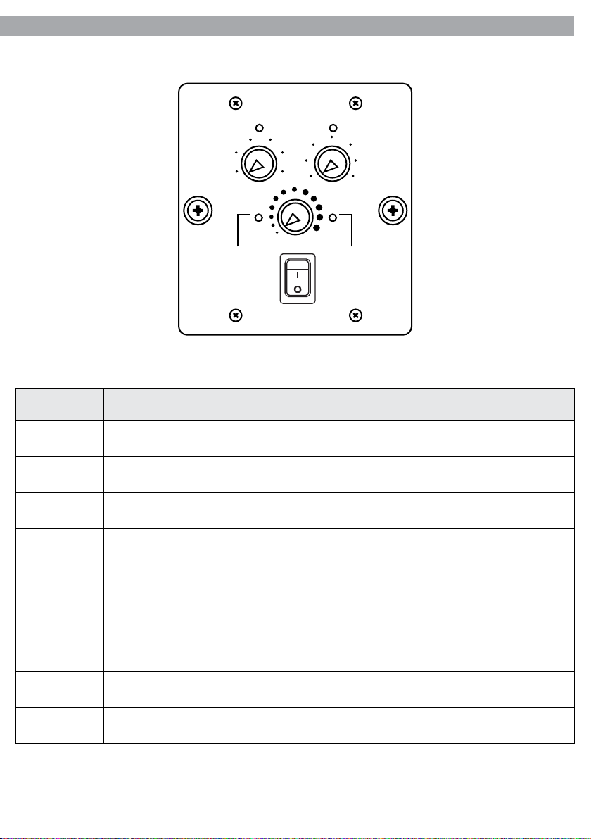
CONTROL PANEL
Power Output
7
101520
5
0
30 0
Minutes Seconds
TIMER READY
4
25
2
Volume
MANUAL
6 8
10
12
15
Fig.2
Function Direction
MANUAL
Press to control the fogger manually, set the fog machine to run continuously, or to set the fog
machine to run o bursts with adjustable time settings.
READY Turns to green when pre-heating process is completed and device is ready for use.
TIMER Turns to green when timer function is enabled (MINUTES knob is set).
VOLUME For adjustment of volume output.
MINUTES To set time interval in minutes between bursts of fog (max value: 30 minutes).
SECONDS To set time duration of fog bursts in seconds (max value: 15 seconds).
POWER Press to switch the fog machine on. The POWER LED will light up in green color.
OUTPUT Turns to green color when fog output is triggered.
INPUT Turns to green color when the fog machine is receiving DMX signal.
NOTE: The on-board control panel can be removed unscrewing the side knobs; it can then be connected to
the unit by the included cable. The length of the cable is 4 m.
Page 22
8
VX1500D
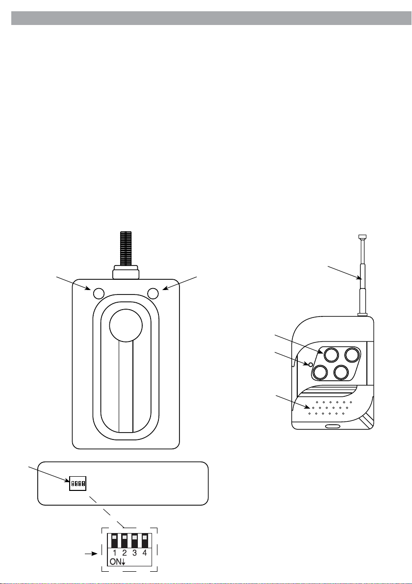
2.3 Wireless remote control
VX1500D is equipped with a multi-channel wireless control system, employing a wired receiver and a 4-key
wireless remote control. Connect the KT-1 receiver to the control panel output, and then turn on the machine. The red LED located on the KT-1 receiver will light up indicating that the machine is in preheating.
When the preheating process is nished and the machine is ready, the LED will light up to green. Now you
can control the machine through the wireless remote control. The timer controller KT-1 is equipped with 4
dipswitches, located on the side, which are in numerical order (1-4), corresponding to wireless remote control keys. The LED on the wireless remote control will light up when you will press any button.
More Vortex machines can be controlled with a single remote control. Each of the keys (1-4) of the remote
control will activate the machines having the same values (1-4) enabled on KT-1 receiver (dipswitch ON
position, downward). To control more machines at the same time using a single key of the remote, just set
them on same channel (1-4).
KT-1 RECEIVER WIRELESS REMOTE CONTROL
15
12
13
14
Switch number
1 2 3 4
KT-1
WIRELESS CONTROLLER
Fig.3
16
17
2
4
1
3
18
Fig.4
12. GREEN LED;
13. RED LED (on KT-1 receiver);
14. DIP-switch [1-4];
15. ANTENNA;
16. BUTTONS [1-4];
17. RED LED (on wireless remote
control);
18. COVER.
Page 23
VX1500D
9
2.4 Linking
Several units can be interconnected via DMX connection:
1. Connect the DMX OUT of the rst unit via a 3-pole XLR cable to the DMX IN of the second unit.
2. Connect the DMX OUT of the second unit to the DMX IN of the next unit, etc.
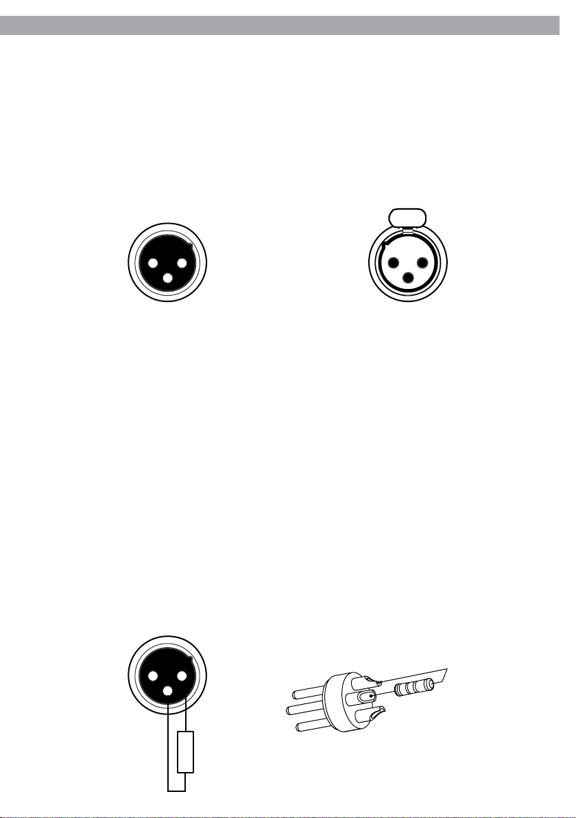
2.5 Connection of the DMX line
DMX connection employs standard XLR connectors. Use shielded pair-twisted cables with 120Ω impedance
and low capacity.
The following diagram shows the connection mode:
DMX - INPUT
XLR plug
Pin1 : GND - Shield
3
Pin2 : - Negative
Pin3 : + Positive
1
21 2
3
DMX - OUTPUT
XLR socket
ATTENTION
The screened parts of the cable (sleeve) must never be connected to the system’s earth, as this would cause
faulty xture and controller operation.
Over long runs can be necessary to insert a DMX level matching amplier.
For those connections the use of balanced microphone cable is not recommended because it cannot transmit control DMX data reliably.
• Connect the controller DMX input to the DMX output of the rst unit.
• Connect the DMX output to the DMX input of the following unit. Connect again the output to the input
of the following unit until all the units are connected in chain.
• When the signal cable has to run longer distance is recommended to insert a DMX termination on the
last unit.
2.6 Construction of the DMX termination
The termination avoids the risk of DMX 512 signals being reected back along the cable when they reaches
the end of the line: under certain conditions and with certain cable lengths, this could cause them to cancel
the original signals.
The termination is prepared by soldering a 120Ω 1/4 W resistor between pins 2 and 3 of the 5-pin male XLR
connector, as shown in gure.
1 2
3
120 Ω
2
3
1
Example:
3 pin XLR connector
Page 24
10
VX1500D
2.7 Adjusting the start address
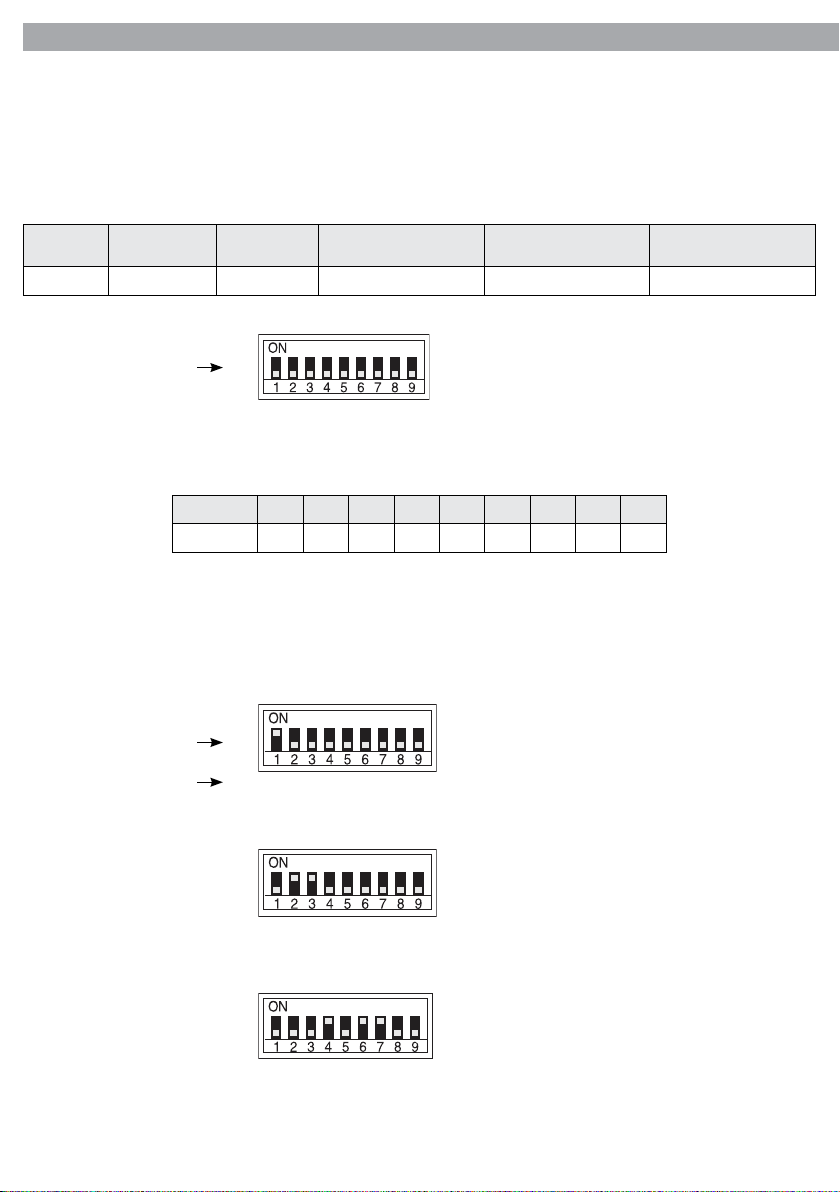
To be able to operate the VX1500D with a light controller, adjust the DMX start address for the rst DMX
channel. If e. g. address 33 on the controller is provided for controlling the function of the rst DMX channel, adjust the start address 33 on the VX1500D. The other functions are then automatically assigned to the
following addresses.
An example with the start address 33 is shown below:
Number of
DMX channels
2 33 33-34 35 37 39
Start address
(example)
Switch number
DMX Address
occupied
1
Next possible start
address for unit No. 1
2
8
4
16
32
64
[ ]
Next possible start
address for unit No. 2
Next possible start
address for unit No. 3
*
128
256
DIP switches and DMX values
Dip Switch 1 2 3 4 5 6 7 8 9
DMX Value
1 2 4 8 16 32 64 128 256
The address is set to start as a binary number by means of DIP-switch No 1 - 9. Thus, it appears the addition
values of DIP-switches positioned to ON.
Examples with the start addresses 1, 6 and 104:
[ ]
16
32
64
*
Start address 1: switch No. 1 set to ON
128
256
Switch number
Place value
1
2
8
4
[ ]
*
1
2
8
4
32
16
64
[ ]
*
1
2
8
4
32
16
64
128
Start address 6: switches No. 2 and 3 set to ON
128
256
Start address 104: switches Nos. 7, 6 and 4 set to ON
256
The easiest way is to start from the highest possible place value and to add the smaller values until the start
address will result.
Page 25

VX1500D
2.8 DMX control
Channel Function
1 Smoke output
2 Interval time
2.9 Troubleshooting
This troubleshooting guide is meant to help solve simple problems. If a problem occurs, carry out the steps
below in sequence until a solution is found. Once the unit operates properly, do not carry out following
steps. If the problem persists, refer servicing to a qualied technician.
Power connected but no fog is emitted:
1. Check the fog uid in the tank.
2. Check the power supply. Plug the unit into grounded electric power supply socket with proper voltage.
3. Check your controller connection or controller receiver connection. Fulll controller usage requirements
for distance, etc. Follow procedures listed in controller manual.
4. Check DMX setup.
5. Disconnect fog machine from electric power supply. Replace fuse with one of the same type.
6. Check the thermic protection. The thermic protection for the smoke machine is located on the boiler
inside the unit.
DANGER! Disconnect the power supply before removing any covers. Live parts inside!
- To restore the thermic protection disconnect the power cord from the supply, unscrew the screws
holding the top cover of the unit and remove the cover. Press the button, on the boiler, to restore.
- Replace the cover and retighten the screw.
- Plug main power cord from the fog machine into the appropriate power supply socket. Wait a few
minutes for heating element to heat up. When the heating process is completed the fog machine is
ready for use.
- Contact technical service if the problem persists.
11
Page 26

Page 27

"
CERTIFICATO DI GARANZIA
GUARANTEE CERTIFICATE
Place Stamp Here
Arancare
Spett.le
Music&Lights S.r.l.
Via Appia Km 136.200
04020 Itri (LT) Italy
"
The guarantee covers the unit
in compliance with existing
regulations. You can nd the
full version of the “General
Il prodotto è coperto da garanzia
in base alle vigenti normative.
Sul sito www.musiclights.it è
possibile consultare il testo
Guarantee Conditions” on our
web site www.musiclights.it.
integrale delle “Condizioni
Generali di Garanzia”.
Abstract
General Guarantee Conditions
Estratto dalle
Condizioni Generali di Garanzia
piece of equipment soon after you
• Please remember to register the
procedere alla registrazione del
• Si prega, dopo l’acquisto, di
purchase it, logging on
www.musiclights.it. The product
can be also registered lling in and
prodotto sul sito www.musiclights.it.
In alternativa il prodotto può essere
registrato compilando e inviando il
sending the form available on your
guarantee certicate.
modulo riportato sul retro.
• Sono esclusi i guasti causati da
• Defects caused by inexperience
imperizia e da uso non appropriato
and incorrect handling of the
equipment are excluded.
eective if the equipment has
been tampered.
• The guarantee will no longer be
• The guarantee makes no provision
dell’apparecchio.
qualora l’apparecchio sia stato
manomesso.
• La garanzia non ha più alcun eetto
sostituzione dell’apparecchio.
• La garanzia non prevede la
for the replacement of the
equipment.
esterne, le lampade, le manopole, gli
• Sono escluse dalla garanzia le parti
switches and removable parts are
• External parts, lamps, handles,
interruttori e le parti asportabili.
• Le spese di trasporto e i rischi
not included in the guarantee.
conseguenti sono a carico del
• Transport costs and subsequent
possessore dell’apparecchio.
risks are responsibility of the
owner of the equipment.
the guarantee is endorsed solely
• For all purposes, the validity of
garanzia è avallata unicamente
dalla presentazione del certicato di
garanzia.
• A tutti gli eetti la validità della
on presentation of the guarantee
certicate.
Page 28
FORM TO BE FILLED IN AND MAILED / CEDOLA DA COMPILARE E SPEDIRE FORM TO BE FILLED IN AND KEPT / CEDOLA DA COMPILARE E CONSERVARE
Purchased by / Acquistato da
Purchasing date
Data acquisto
del Rivenditore
ZIP CODE / C.A.P.
PROV.
CITY / CITTA’
ADDRESS / VIA N.
NAME / NOME
Dealer’s stamp
and signature
Timbro e rma
SURNAME / COGNOME
SERIAL N° / SERIE N°
MODEL / MODELLO
Purchased by / Acquistato da
Purchasing date
Data acquisto
del Rivenditore
ZIP CODE / C.A.P.
PROV.
CITY / CITTA’
ADDRESS / VIA N.
NAME / NOME
Dealer’s stamp
and signature
Timbro e rma
SURNAME / COGNOME
SERIAL N° / SERIE N°
MODEL / MODELLO
"
Page 29

Page 30

Page 31

Page 32

©2011 Music & Lights S.r.l.PROLIGHTS è un brand di proprietà della Music & Lights S.r.l. PROLIGHTS is a brand of Music & Lights S.r.l .company.
Music & Lights S.r.l. entertainment technologies
Via Appia km 136,200 - 04020 Itri (LT) ITALY
tel. +39 0771 72190 fax +39 0771 721955
www.musiclights.it [email protected]
ISO 9001:2008
Certified Company
 Loading...