

Page 1
VN2000 Flow Meters
Transmitter
VRX-UM-02233-EN-02 (June 2017)
User Manual
Page 2

VN2000 Flow Meters, Transmitter
Page ii June 2017VRX-UM-02233-EN-02
Page 3

User Manual
CONTENTS
Purpose of this Document. . . . . . . . . . . . . . . . . . . . . . . . . . . . . . . . . . . . . . . . . . . . . . . . . . . . . . . . . . . . . . . . 5
Unpacking and Inspection . . . . . . . . . . . . . . . . . . . . . . . . . . . . . . . . . . . . . . . . . . . . . . . . . . . . . . . . . . . . . . . 5
Storage . . . . . . . . . . . . . . . . . . . . . . . . . . . . . . . . . . . . . . . . . . . . . . . . . . . . . . . . . . . . . . . . . . . . . . . . . 5
Introduction. . . . . . . . . . . . . . . . . . . . . . . . . . . . . . . . . . . . . . . . . . . . . . . . . . . . . . . . . . . . . . . . . . . . . . . . . 5
Product Label. . . . . . . . . . . . . . . . . . . . . . . . . . . . . . . . . . . . . . . . . . . . . . . . . . . . . . . . . . . . . . . . . . . . . . . . 5
Installing the Transmitter . . . . . . . . . . . . . . . . . . . . . . . . . . . . . . . . . . . . . . . . . . . . . . . . . . . . . . . . . . . . . . . . 6
Rotating the Display. . . . . . . . . . . . . . . . . . . . . . . . . . . . . . . . . . . . . . . . . . . . . . . . . . . . . . . . . . . . . . . . . 6
Wiring. . . . . . . . . . . . . . . . . . . . . . . . . . . . . . . . . . . . . . . . . . . . . . . . . . . . . . . . . . . . . . . . . . . . . . . . . . . . . 7
Grounding . . . . . . . . . . . . . . . . . . . . . . . . . . . . . . . . . . . . . . . . . . . . . . . . . . . . . . . . . . . . . . . . . . . . . . . 7
Analog Version, 4…20 mA . . . . . . . . . . . . . . . . . . . . . . . . . . . . . . . . . . . . . . . . . . . . . . . . . . . . . . . . . . . . . 7
Connecting Cables . . . . . . . . . . . . . . . . . . . . . . . . . . . . . . . . . . . . . . . . . . . . . . . . . . . . . . . . . . . . . . . . . . . . 8
Operating the VN2000 Transmitter . . . . . . . . . . . . . . . . . . . . . . . . . . . . . . . . . . . . . . . . . . . . . . . . . . . . . . . . . . 9
Control Panel Keys. . . . . . . . . . . . . . . . . . . . . . . . . . . . . . . . . . . . . . . . . . . . . . . . . . . . . . . . . . . . . . . . . . 9
Display Modes . . . . . . . . . . . . . . . . . . . . . . . . . . . . . . . . . . . . . . . . . . . . . . . . . . . . . . . . . . . . . . . . . . . 10
Programming Mode Level 1. . . . . . . . . . . . . . . . . . . . . . . . . . . . . . . . . . . . . . . . . . . . . . . . . . . . . . . . . . . 12
Programming Mode Level 2 (A1-SS78MB-C). . . . . . . . . . . . . . . . . . . . . . . . . . . . . . . . . . . . . . . . . . . . . . . . . 15
Programming Mode Level 3 (A1-SS78MB-S). . . . . . . . . . . . . . . . . . . . . . . . . . . . . . . . . . . . . . . . . . . . . . . . . 18
Specications . . . . . . . . . . . . . . . . . . . . . . . . . . . . . . . . . . . . . . . . . . . . . . . . . . . . . . . . . . . . . . . . . . . . . . . 21
Alarm Messages . . . . . . . . . . . . . . . . . . . . . . . . . . . . . . . . . . . . . . . . . . . . . . . . . . . . . . . . . . . . . . . . . . . . . 22
Troubleshooting . . . . . . . . . . . . . . . . . . . . . . . . . . . . . . . . . . . . . . . . . . . . . . . . . . . . . . . . . . . . . . . . . . . . . 23
Removing VN2000 Transmitter Electronics . . . . . . . . . . . . . . . . . . . . . . . . . . . . . . . . . . . . . . . . . . . . . . . . . . . . 23
North American Pipe Schedules . . . . . . . . . . . . . . . . . . . . . . . . . . . . . . . . . . . . . . . . . . . . . . . . . . . . . . . . . . . 24
Page iii June 2017 VRX-UM-02233-EN-02
Page 4

VN2000 Flow Meters, Transmitter
Page iv June 2017VRX-UM-02233-EN-02
Page 5
Purpose of this Document
PURPOSE OF THIS DOCUMENT
The purpose of this document is to provide instructions the installation, wiring and operation of the VN2000 Transmitter.
MPORTANTI
Read this manual carefully before attempting any installation or operation.
Keep the manual in an accessible location for future reference.
UNPACKING AND INSPECTION
Upon opening the shipping container, visually inspect the product and applicable accessories for any physical damage such
as scratches, loose or broken parts, or any other sign of damage that may have occurred during shipment.
OTE:N If damage is found, request an inspection by the carrier’s agent within 48 hours of delivery and file a claim with the
carrier. A claim for equipment damage in transit is the sole responsibility of the purchaser.
Storage
If the meter is not scheduled for installation soon after delivery and must be stored:
• After inspection, re-pack the meter into its original packing.
• If the meter being stored has been previously installed, remove all process fluids and corrosives.
• Store in a clean, dry site free of mechanical vibration, shock and chemical corrosives.
INTRODUCTION
The VN2000 Transmitter is supplied with all vortex flow meters. It is designed to be located on the head of the meter or
remotely mounted from the meter, for easy viewing and access. Three configurations are available:
• The VN2000 Volumetric Flow Transmitter has a large, easy-to-read LCD indicator that displays flow rate and accumulated
total flow.
• The VN2000 Mass Flow Transmitter also displays temperature compensated flow rate.
• The VN2000 Energy Flow Transmitter also displays compensated flow rate (BTU/hr or kBTU/hr), total flow (total BTU),
operating temperature, and outgoing and returning temperature.
The control panel keys used to program parameters including engineering units, line sizes (insertion only), 4…20 mA span
adjustments and to recalibrate for new flow conditions.
All internal parameters of the flow meter can be read via the VN2000 Transmitter.
The transmitter has a built-in non-volatile memory for setup and calibration data with the ability to field-calibrate. All
transmitters are factory-tested and programmed.
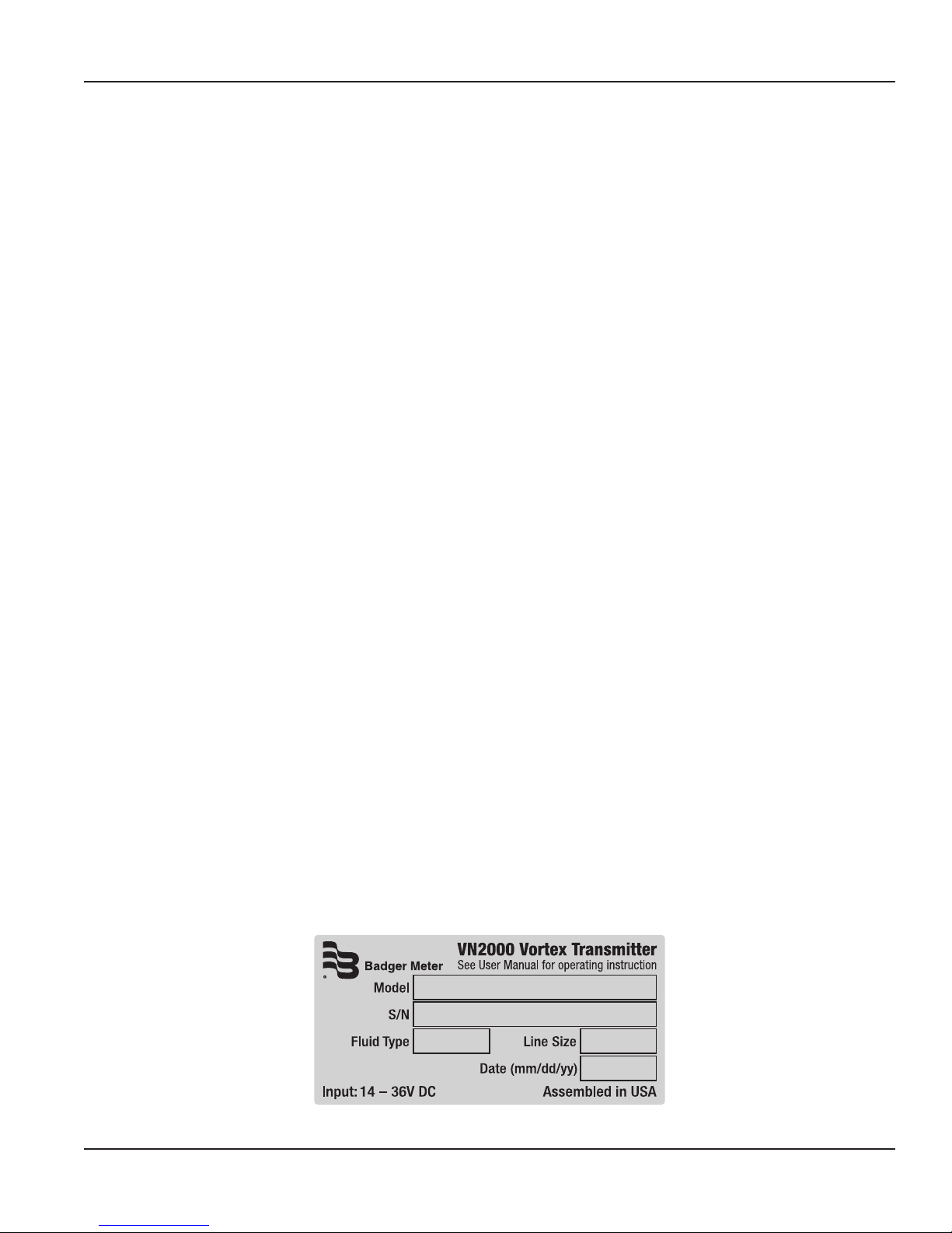
PRODUCT LABEL
Figure 1: VN2000 transmitter label
Page 5 June 2017 VRX-UM-02233-EN-02
Page 6
Installing the Transmitter
INSTALLING THE TRANSMITTER
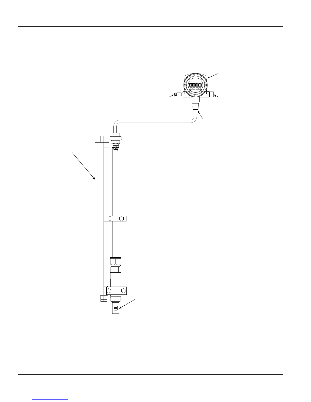
The remote transmitter enclosure has a mounting bracket for wall mounting. Locate the enclosure within 30 feet of the
pipeline sensor and at eye level for easy viewing and access to the control panel keys for programming.
Remote
Transmitter
Insertion Tool
To Power
and Outputs
External
RTD Input
(energy
meter only)
To Sensor
(remote only)
Rotating the Display
To adjust the orientation of the display for easier viewing:
1. Unscrew and remove the faceplate cover.
2. Gently lift and turn the faceplate to the desired orientation.
3. Return the faceplate into the enclosure.
4. Replace the faceplate cover.
Page 6 June 2017VRX-UM-02233-EN-02
Sensor Element
Figure 2: Remote installation
Page 7
Wiring
WIRING
The transmitter ships with a cable that has a connector on one end and flying leads with 4 or 5 wires on the other end. Use
this cable to wire the power and outputs. The transmitter is available with two output options:
• 4…20 mA/pulse output; uses a 4-wire cable
• Modbus RTU; uses a 5-wire output
Display Only (No Output) Black wire 24 VDC
Blue wire Ground
Pulse Output Black wire 24 VDC
Blue wire Ground
Brown wire Pulse DC power
White wire Pulse output
Modbus Output Black wire 24 VDC
Blue wire Ground
Gray wire Data +
Pink wire Data -
White wire Signal Ground (only connect if needed)
4…20 mA Output, Loop Powered Black wire 10…36 VDC
Blue wire 4…20 mA signal
Table 1: Wiring
Grounding
Ground the power supply to DC ground or good earth ground. DO NOT connect to AC ground.
Analog Version, 4…20 mA
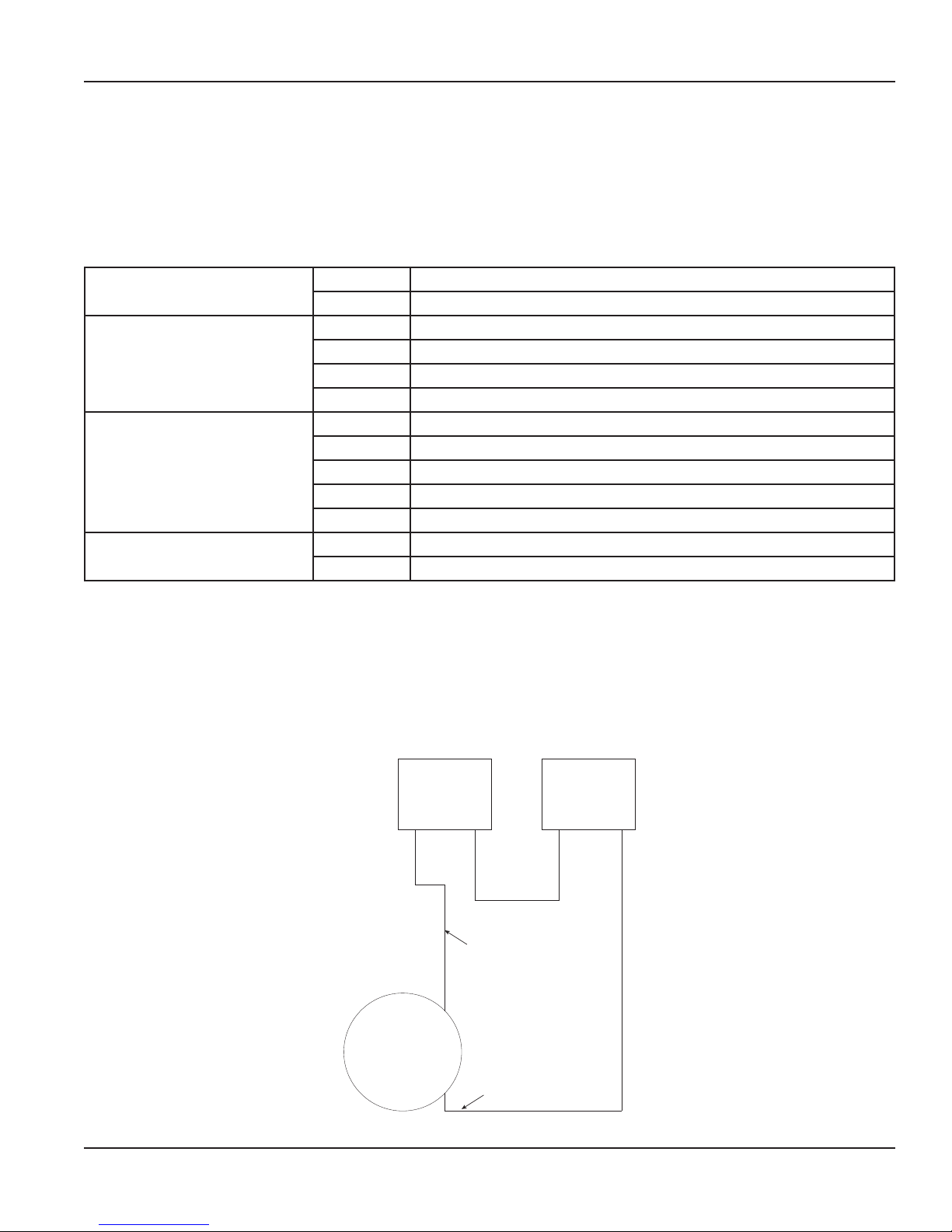
To wire for power, use 24 gauge with multi-pin power connector supplied with meter. Do not run the wire over transformers,
motors, or any other magnetic field generating devices. Connect the end of wire to 24V DC for loop powering the device.
Data Logger or PLC
4 . . . 20 mA
Analog Input
Negative/
Common
_ _
Input
Power Supply
Positive Negative
+
Flow Meter
24V DC
_
BLACK Wire (Positive)
+
-
BLUE Wire
Figure 3: Analog version wiring diagram
Page 7 June 2017 VRX-UM-02233-EN-02
Page 8
Connecting Cables
CONNECTING CABLES
Connecting to the flow meter is easy using our plug-and-play design. No internal wiring is required. All cables are included
with the meter.
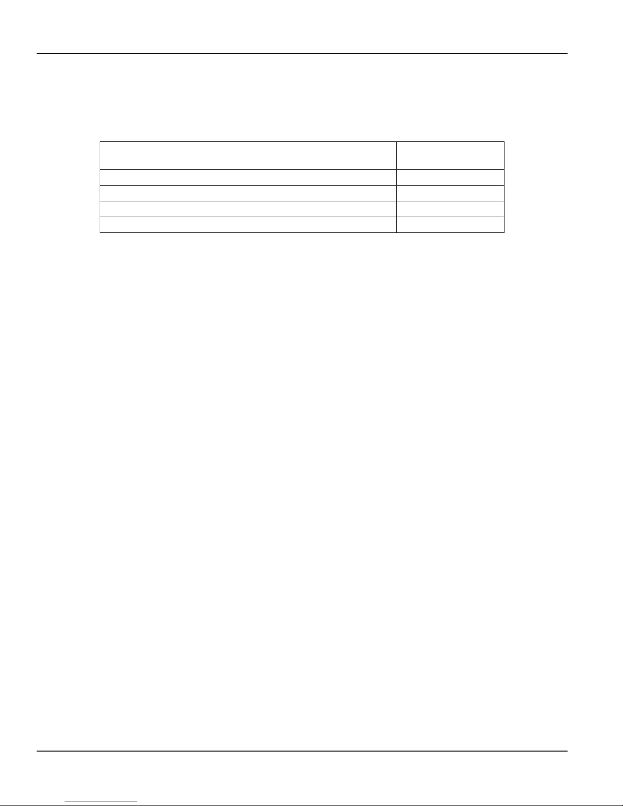
Cable Description Replacement
Part Number
Transmitter power, 4…20 mA 4-pin cable, 9 ft (3 m) VNA-CBL-PWR-AA-09
Transmitter power, Modbus RTU 5-pin cable, 9 ft (3 m) VNA-CBL-PWR-MA-09
Transmitter-sensor or external RTD cable, 9 ft (3 m) VNA-CBL-SNR-09
Transmitter-sensor or external RTD cable, 30 ft (9 m) VNA-CBL-SNR-30
Table 2: Transmitter cables
1. Connect the wired end of the cordset to the power supply and outputs.
OTE:N DO NOT USE 110…220V AC without using an optional AC-to-DC power supply, available as an accessory.
2. Connect the other end of the cordset into the remote transmitter. Find the matching keyway between the plug and the
connector in the enclosure. When the key nds the grooved slot, push the plug into the connector.
3. Slowly tighten the threaded connection. Make sure the plug is tightened all the way down into the plug socket.
4. If the transmitter is mounted remotely, use the cordset with connectors on both ends to connect to the sensor.
5. If the meter is an energy meter with an external RTD, use the cordset with connectors on both ends to connect to the
external RTD. The external RTD and remote sensor cable are identical.
6. Apply power to the power supply.
7. The screen displays the version of the operating software.
8. After approximately 5 seconds, the rate and total display (if ow is present).
Page 8 June 2017VRX-UM-02233-EN-02
Page 9
OPERATING THE VN2000 TRANSMITTER
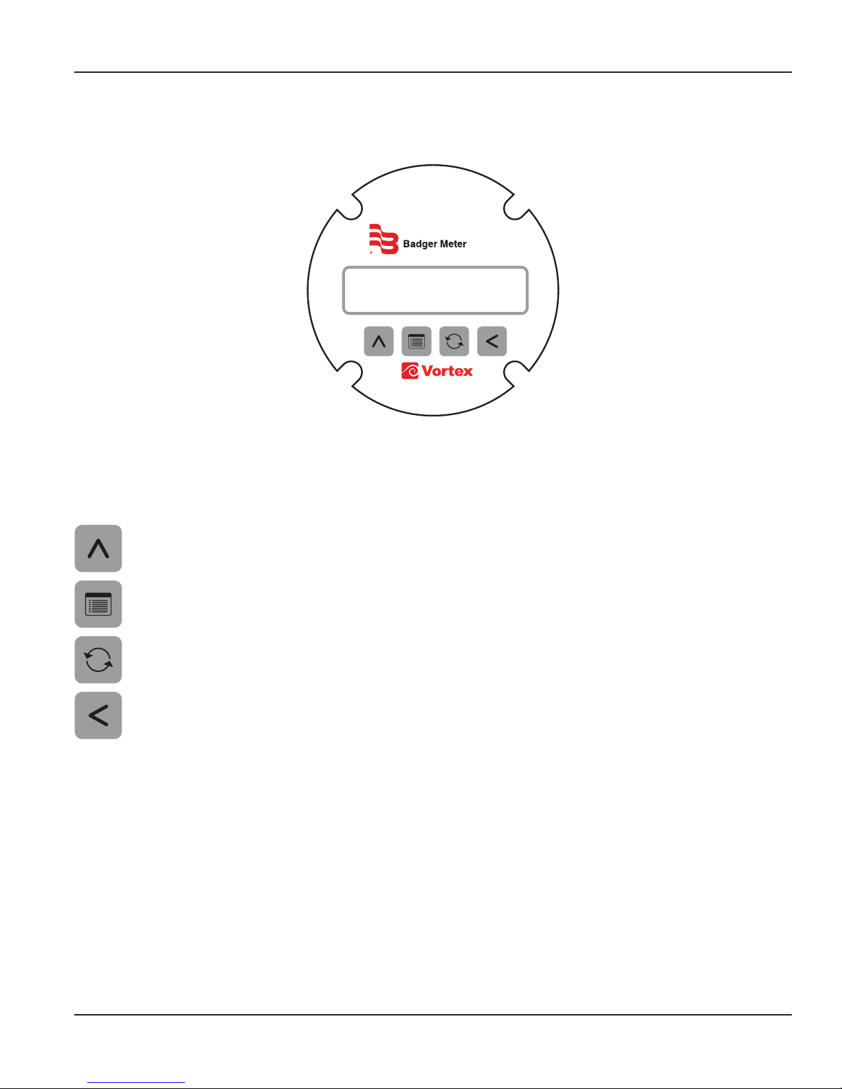
Figure 4: VN2000 transmitter
Operating the VN2000 Transmitter
VN2000
Control Panel Keys
To access the control panel keys, unscrew and remove the faceplate cover.
In Password or Program mode, press the Up Arrow key to increment the selected digit by one.
In an idle state with the temperature adjustment enabled, press to toggle the display between
Totalizer and Temperature.
Press the Menu key to move the control panel keys from an idle state to the Password mode.
Press the Reset key to reset the totalizer.
In Password or Program mode, press the Left Arrow key to move the cursor one digit to the left. If the cursor is
already in the left-most position, press to move the cursor to the right-most position.
Page 9 June 2017 VRX-UM-02233-EN-02
Page 10
Operating the VN2000 Transmitter
BADGER METER
VN2000 REV 1
0.0000 LB/HR
0000000000 LB
0.0000 LB/HR
BAD TEMPERATURE
Display Modes
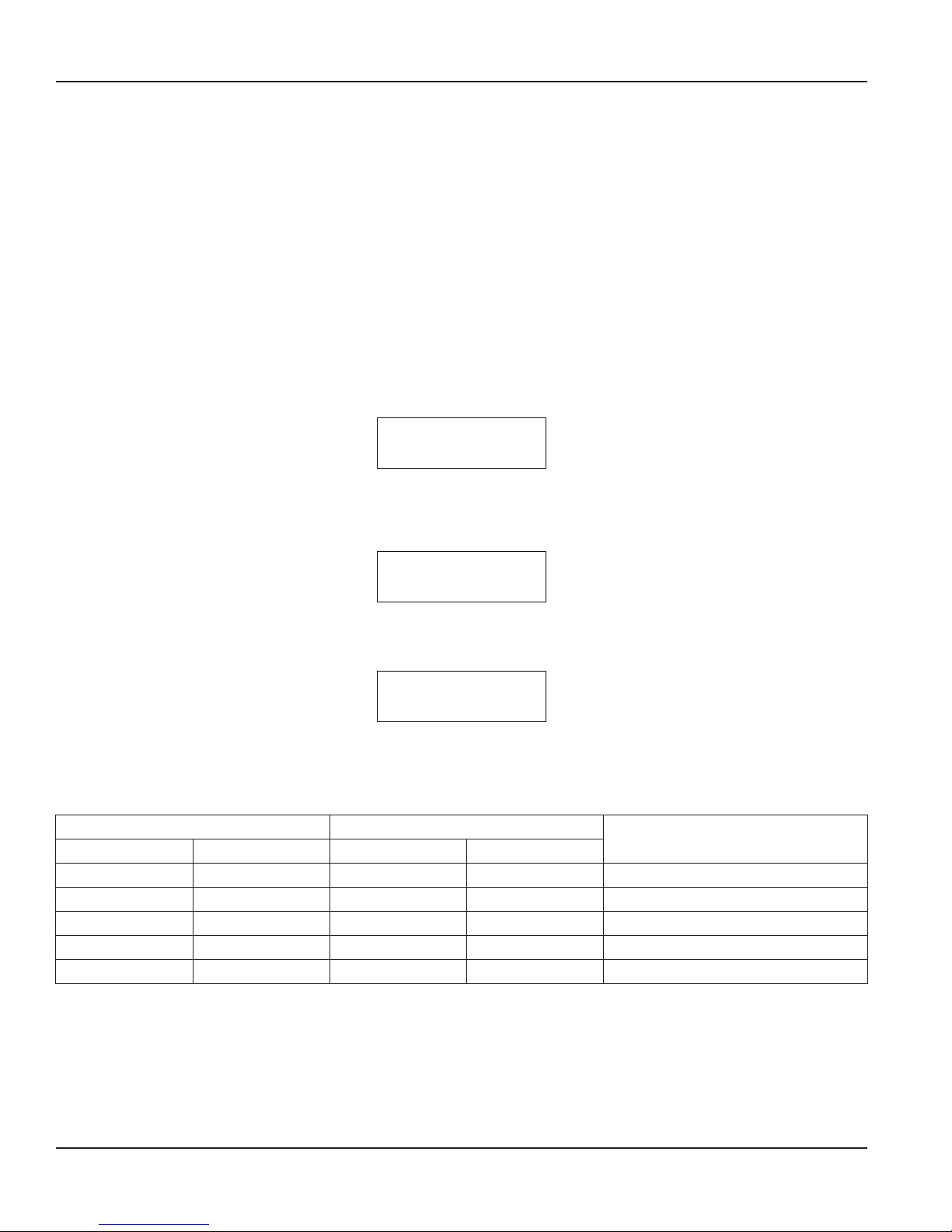
The VN2000 Transmitter has a 32-character display that is organized as two rows of 16 characters each.
The display software is designed to operate in one of three modes.
OTE:N The options available in the Programming mode will vary, depending on the media (steam, gas or liquid) for which
the transmitter was configured:
• Startup
• Operational
• Programming (Three Levels)
Startup Mode
The Startup mode begins when the system is first powered on or when the system transitions from the programming mode.
The initial screen displays for about 10 seconds. The top line of the display shows the company name. The bottom line shows
the product name and the hardware revision number. The display cannot be changed during this mode.
Operational Mode
The Operational mode is the main mode of the transmitter. The top line of the display shows the Flow Rate. The bottom line of
the display shows the Totalizer value.
The bottom line of the display can also have alternate uses in this mode. For example, if the transmitter detects an event, it
displays an alarm message alternating with the Totalizer value. See “Alarm Messages” on page 22 for a list of possible alarms
and how to clear them.
In the Operational mode, the transmitter displays the Temperature and Pressure values alternating with the Totalizer value.
The Temperature and Pressure values are available only if they have been configured to be read and they are not being
overridden with manual values. This portion of the display shows either Temperature, Pressure or both. The table below shows
what displays.
Temperature Pressure
Enabled Manual Override Enabled Manual Override
yes no yes no Temperature and Pressure
yes no yes yes Temperature
yes no no — Temperature
yes yes yes no Pressure
no — yes no Pressure
Table 3: Temperature and pressure values
Displayed
Page 10 June 2017VRX-UM-02233-EN-02
Page 11

Operating the VN2000 Transmitter
In all other cases, the option to display Temperature or Pressure is not available.
To activate the option to display Temperature or Pressure, press Up Arrow to scroll through three display patterns:
• Totalizer value only
• Temperature and Pressure only
• Alternating the display between the Totalizer and the Temperature/Pressure display
OTE:N Independent of the active display pattern, any event alert message automatically alternates with the display or is
included in the alternating pattern.
OTE:N When the system is powered ON, the warning messages, display pattern, remote message suppression and any
remote messages are cleared.
Reset Total
Press Reset to reset total.
Programming Mode
The transmitter automatically exits the programming mode after 20 seconds with no key presses.
The three levels of the Programming Mode are detailed in the following sections.
Page 11 June 2017 VRX-UM-02233-EN-02
Page 12
Operating the VN2000 Transmitter
LINE SIZE
6 in
Programming Mode Level 1
OTE:N Currently, the word “Pressure” displays on the screen, but the Pressure feature is not yet supported.
OTE:N The options available in the Programming mode will vary, depending on the fluid type (steam, gas or liquid) and
function (Mass, Volumetric or Energy) for which the transmitter is configured:
With power ON and Flow Rate and Flow Total displayed, press Menu to cycle through the Level 1 programming options:
• Pipe Size (Insertion meters only)
• Units of Measure
• Flow Measurement Time Interval
• K-Factor (Inline meters only)
• Low Flow Cutoff (4 mA)
• Max Flow (20 mA)
• Pulse Rate
• Pulse Width
Pipe (Line) Size (Insertion Only)
The transmitter automatically calculates the flow rate from the pipe dimensions and fluid velocity. The K-Factor Source option
in Programming Mode Level 3 determines which type of pipe dimension entry appears.
Line Size DN Pipe ID
Select pipe size in inches for ASME pipe.
To set the pipe schedule, select the
Schedule in Programming Mode Level 3
Press Up Arrow to increase the size. The
list will wrap around and start with the
smallest pipe size
Select pipe size in millimeters nominal
diameter (DN) pipe
Press Up Arrow to increase the size. The
list will wrap around and start with the
smallest pipe size
Table 4: Pipe size settings
Enter the pipe size in inches for the
inner diameter (ID)
Press Left Arrow to select the digit to
change. Press Up Arrow to increase the
number
Page 12 June 2017VRX-UM-02233-EN-02
Page 13
Operating the VN2000 Transmitter
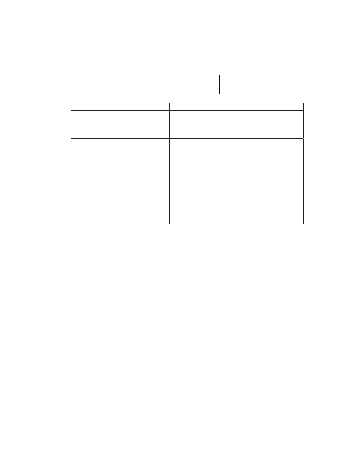
ENGINEERING UNIT
GAL
Units of Measure (Engineering Units)
Press Up Arrow to scroll through the engineering units. Stop pressing when the proper unit is displayed. That unit is now the
unit of measure. When the units are changed, the Flow Total and Flow Rate are automatically adjusted.
Units Base Steam Liquids Gases
English
Metric
Pounds (LB)
Tons (TON)
Cubic Feet (CFT)
Gallons (GAL)
Kilograms (KG)
Tonns (TNN)
Cubic Meters (CUM)
Liters (LTR)
Pounds (LB)
Tons (TON)
Cubic Feet (CFT)
Gallons (GAL)
Kilograms (KG)
Tonns (TNN)
Cubic Meters (CUM)
Liters (LTR)
Pounds (LB)
Tons (TON)
Cubic Feet (CFT)
U.S. Gallons (GAL)
Kilograms (KG)
Metric Tons (TNN)
Natural Cubic Meters (Nm3)
Natural Liters (Nlt)
Pounds (LB)
Actual English — —
Tons (TON)
Actual Cubic Feet (Acf)
U.S. Gallons (GAL)
Kilograms (KG)
Natural Metric — —
Metric Tons (TNN)
Actual Cubic Meters (Am3)
Actual Liters (Alt)
Table 5: Units of measure
Page 13 June 2017 VRX-UM-02233-EN-02
Page 14

Operating the VN2000 Transmitter
TIME BASE
HR
LOW FLOW CUTOFF
000000 GAL/HR
MAX FLOW (20 MA)
0057000 GAL/HR
Units of Measure (Time Base)
Press Up Arrow to scroll through the Time Base options. Stop pressing when the proper time is displayed. The options are SEC
(seconds), MIN (minutes), HR (hour) and DAY.
K-Factor (Inline Meters Only)
The K-Factor is used for VN2000 inline vortex flow meters. The transmitter automatically generates the K-Factor based on the
flow meter model type and bore size.
OTE:N DO NOT change the K-factor that has come with your device without first consulting the factory.
To change the K-Factor, press Left Arrow to move the cursor under the digit to be changed. Press Up Arrow to change the
digit. If the K-Factor does not match the “VN2000 SF” found on the bottom right of your sizing sheet, contact the manufacturer.
Low Flow Cutoff
The Low Flow Cutoff is factory-set to the minimum flow rate of the meter. Below this number, the meter gives 4 mA output and
displays zero flow reading.
The meter reading drops to zero when the flow drops below the minimum setting. To measure flow below the minimum
range of measurement, lower the setting. Press Up Arrow to increment each digit. Press Left Arrow to move the cursor to the
next digit.
Max Flow (20 mA)
Use Max Flow to span and adjust the 4 mA and 20 mA range based on your flow range. The number must represent the 20 mA
setting on the receiving PLC or other analog input device. Once this number matches what 20 mA represents on the receiving
device, the 4…20 mA span will be correct and the meter’s output from Max Flow to zero reading will match what is showing
on the display. For example, if Max Flow is set to 500, then 250 will output 12 mA (12 mA is in the middle of 4…20 and 250 is
the middle of 500).
Pulse Rate
The Pulse Rate option adjusts the number of pulses for a flow unit and the number of units that are represented by a pulse.
Press Up Arrow to scroll through the pulse rate options:
• 1 Pulse = 1 unit
• 10 Pulses = 1 unit
• 100 Pulses = 1 unit
• 1000 Pulses = 1 unit
• 1 Pulse = 10 units
• 1 Pulse = 100 units
• 1 Pulse = 1000 units
• Off = Turns off pulser
Pulse Width
The pulse width is predefined with 5 widths and directions of pulse.
• 10, 20, 50, 100 or 150 ms negative
• 10, 20, 50, 100 or 150 ms positive
Page 14 June 2017VRX-UM-02233-EN-02
Page 15
Operating the VN2000 Transmitter
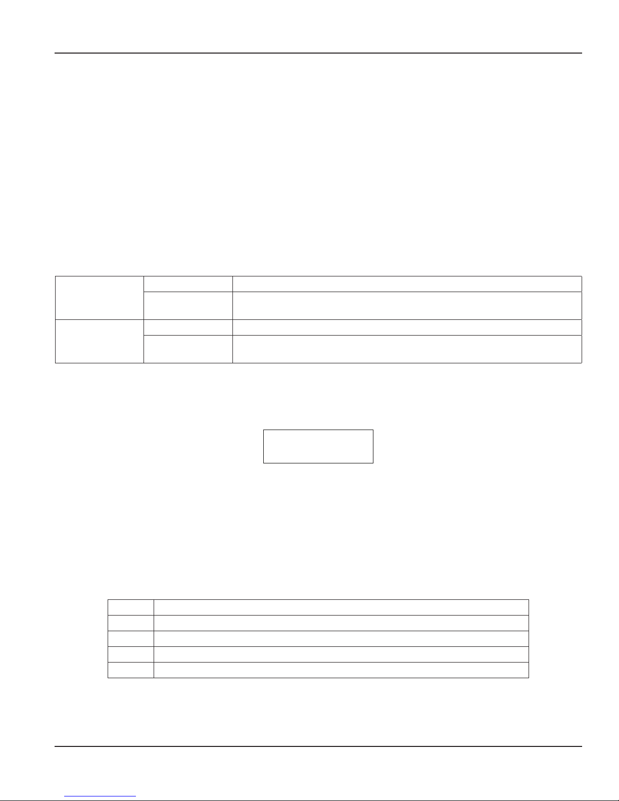
ADJUST FLOW?
OFF
Programming Mode Level 2 (A1-SS78MB-C)
With the power ON and Flow Rate and Flow Total displayed, press Left Arrow. When the message “A1-SS78MB-C” displays,
press Menu to scroll through the second programming level options.
Level 2 programming options:
• Mass Flow Mode
• Flow Adjust (In-Field Calibration)
• Vortex Threshold
• Change Password
Mass Flow Temperature/Pressure Input (Gas and BTU/Energy Meters Only)
The Mass Flow Mode turns on the other RTD and/or pressure sensors (if present) in the flow meter. It also allows the entry of a
mean pressure and/or temperature for fixed Mas Flow calculations
Press Up Arrow to scroll through the Mass Flow Mode options.
Auto Uses the internal RTD reading in the Mass Flow calculations
Temperature Input
Pressure Input
Manual
Auto (Future)
Manual-Pressure
Uses a fixed temperature in the mass flow calculations. Enter mean temperature
when prompted. For BTU/Energy meters, enter source and return temperature
Uses a fixed pressure in the mass flow calculations. Enter mean pressure when
prompted
Table 6: Mass flow mode options
Flow Adjust (Adjust Flow?)
The Flow Adjust option allows for field calibration of each vortex flow meter without changing core application data, such as
the K-factor.
Use Flow Adjust only as a last resort if there can be no change to the location of the installation or overall flow profile due to:
• Inadequate upstream and downstream piping
• Large piping
• Obstructions
• Overall flow turbulence
The Flow Adjust option only operates—and should only be used—for in-field calibration while the meter is reading
steady flow.
Press Up Arrow to scroll through the in-field calibration options:
Set Flow Calibrates based on flow rate
Set Ratio Calibrates based on total accumulated flow
Reset Removes any calibration previously done and returns the factory settings to the meter
ON Displays when the meter has been calibrated and the calibration option is ON
OFF Displays when no calibration has been done
Table 7: Flow adjust options
Page 15 June 2017 VRX-UM-02233-EN-02
Page 16
Operating the VN2000 Transmitter
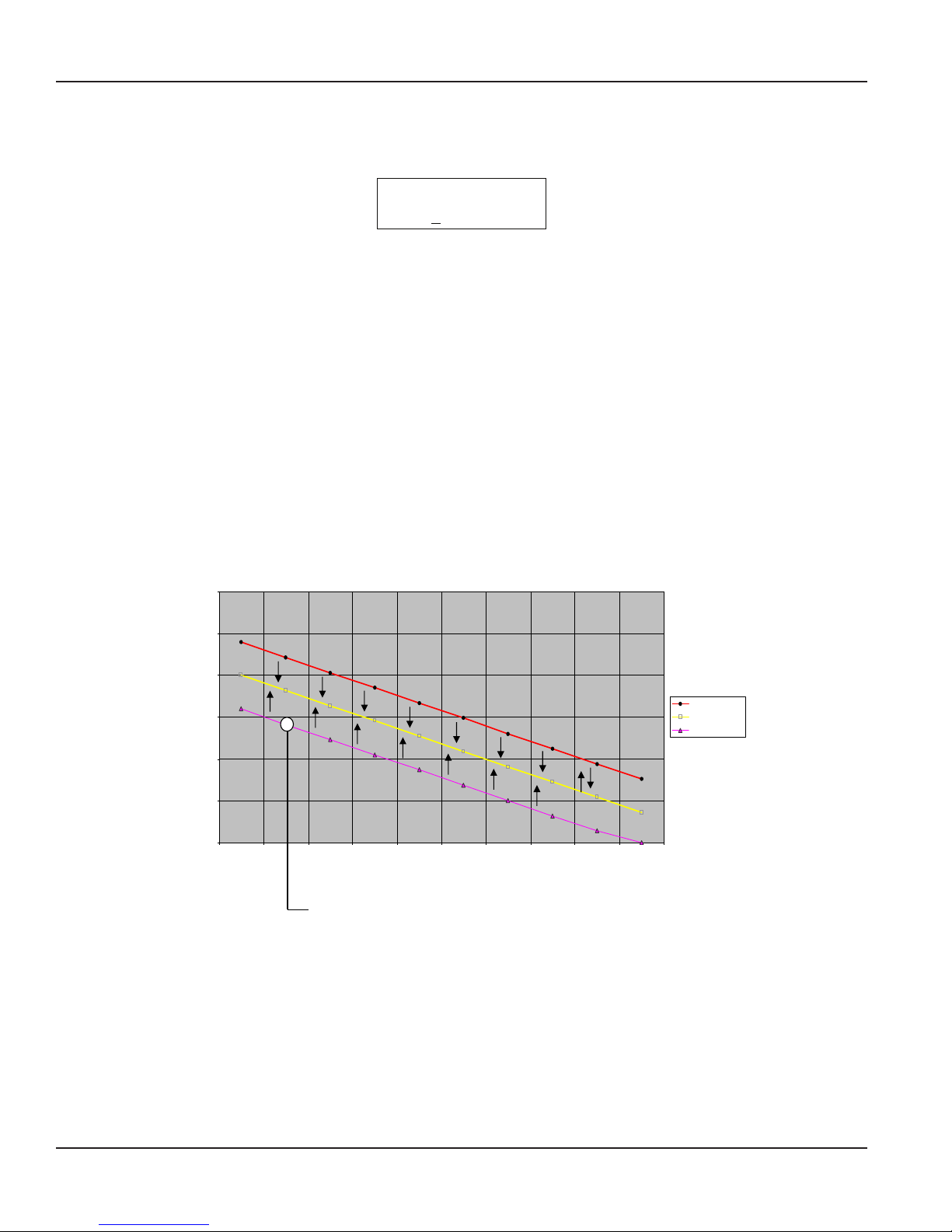
NEW FLOW RATE
000000 GAL/HR
Set Flow
1. Press P. The “New Flow Rate” message displays. This is a snapshot of the current ow rate.
2. Press Left Arrow to move the cursor and Up Arrow to change the digits to the desired ow rate.
3. Press Menu and let the meter come back to Flow Rate and Flow Total.
The VN2000 Transmitter adjusts the internal calibration curve, allowing the new flow rate to appear.
Set Ratio
1. When the Set Ratio menu displays, press P. The “Ratio – 1.00” message displays.
2. Press Left Arrow to move the cursor and Up Arrow to change the digits to the desired ratio.
3. Press Menu and let the meter come back to Flow Rate and Flow Total.
The VN2000 Transmitter adjusts the internal calibration curve, allowing the new ratio to appear.
The ratio of one (1) equals the current total in the VN2000 Transmitter totalizer.
Example 1: If the total accumulated flow is 25% higher than it should, change the ratio to 0.75% to lower the internal curve
and all accumulated flow readings by 25%.
Example 2: If the total accumulated flow is 25% lower than it should, change the ratio to 1.25% to raise the internal curve
and all accumulated flow readings by 25% .
OTE:N Brownouts and blackouts do not affect the in-field calibrated settings. Select RESET to completely remove all in-field
calibrated settings.
300
250
200.00
200
150
100
Flo w U nits m 3/hr
50
0
12345 6789 10
181.82
163.64
145.45
127.27
109.09
90.91
72.73
54.55
Calibration Points
Current Flow Rate is being aected by poor ow prole,
driving the ow rate lower. This entire curve can be adjusted
upward to the correct Flow Rate by entering the correct Flow Rate
in Flow Adjust mode: 181 m3/hr. The new curve will have
repeatability of ± 0.25%.
Upper Turbulence
Flow Rate
Lower Turbulence
36.36
Page 16 June 2017VRX-UM-02233-EN-02
Figure 5: In-field calibration points
Page 17

Operating the VN2000 Transmitter
Vortex Threshold
The Vortex Threshold feature:
• Is designed to the get the most out of low flow conditions.
• Is meant to be used in high density fluids like liquids where signals are large.
• Is set at the factory and should not be changed unless consulting the factory first.
• Has settings range from 0…7, with 0 being the most sensitive and 7 being the least sensitive.
The typical Vortex Threshold setting for liquid, gases and steam is 3. If the setting is not at 3, consult the factory.
When to use the Vortex Threshold settings:
• The flow meter has been installed and the operating condition is very close or below the meter’s minimum.
• There is zero flow rate at normal operating conditions, or the flow rate is bouncing to zero, or the flow rate is much lower
than expected. In this case, increase the sensitivity of the dual sensors by lowering the Vortex Threshold settings.
◊ To increase the sensitivity of the dual sensors, lower the threshold to 2, 1, or 0.
◊ Zero (0) is the most sensitive settings.
◊ Do not raise the threshold setting above 3, unless the factory recommends it.
Change Password
The Password Security feature lets you create a password to stop any unauthorized user from tampering with settings or
parameters within the VN2000 Transmitter electronics.
Every VN2000 Transmitter does not come with a password. The security password can be created in this program mode. Any
user will be required to enter this password before entering into the Program Mode. If the correct password is not entered, NO
flow meter settings or parameters can be changed.
How to set your password:
1. Press Menu until the Enter Password Setting option appears. The default Password is 000000.
2. Press Left Arrow to position the cursor under each number.
3. Press Up Arrow to select each digit.
4. Confirm the password by repeating steps 2 and 3.
5. Let the program mode sit for 10 seconds until Flow Rate and Flow Total displays.
If any user wants to change flow meter settings, they have to first enter the correct password.
OTE:N If an incorrect password is entered, the VN2000 Transmitter immediately reverts back to the Flow Rate and
Flow Total display.
Page 17 June 2017 VRX-UM-02233-EN-02
Page 18

Operating the VN2000 Transmitter
Programming Mode Level 3 (A1-SS78MB-S)
With the power ON and Flow Rate and Flow Total displayed, press Left Arrow, then Up Arrow. When the message
“A1-SS78MB-S” displays, press Menu to scroll through the Level 3 programming options:
• 4 mA Field Calibration
• 20 mA Field Calibration
• Units Base (English or Metric)
• Dampening
• Meter Type
• K-Factor Source (Insertion meters only)
• K-Factor (Insertion meters only)
• Schedule (Insertion meters only)
• Gas Constant (if Fluid is set to Gas)
• Temperature Calibration
• Application
• Settings
• Vibration Control
4 mA Field Calibrate
The 4 mA Field Calibrate option is a trim function that is factory-calibrated but can be field-adjusted if the equipment is not
seeing exactly 4 mA at zero flow due to ground loops or other equipment issues not relating to the flow meter.
20 mA Field Calibrate
MPORTANTI
Do not change this setting.
The 20 mA Field Calibrate option is used at the factory to calibrate the maximum output of the flow meter. The typical setting
range is 3960…4000.
Units Base
The Units Base option is used at the factory to set up all internal units to English or Metric.
Dampening
The Dampening option allows adjustment of the Flow Rate Averaging or Dampening. The most common use for this feature is
to eliminate high flow variation or to lessen the flow rate change on the display that is due to the flow dynamics in the pipe.
This option allows for stabilization of the flow reading when erratic flow is present in the pipe.
Press Up Arrow to scroll through the Dampening options:
• The Auto Setting is used for steam and gases:
◊ Auto Setting uses mathematical calculations to determine the correct dampening setting.
◊ When the flow rate is steady (not changing more than 15% from one reading to the next), the dampening is set to the
highest setting to provide stable and reliable flow readings.
◊ When the flow rate is fluctuating (changing more than 15% from one reading to the next), dampening is decreased to
provide a quick response time to flow rate changes.
• The 1-5 Setting sets faster response times.
• The 6-9 Setting sets slower response times for steadier instantaneous flow readings.
Page 18 June 2017VRX-UM-02233-EN-02
Page 19
Operating the VN2000 Transmitter
MPORTANTI
All liquid applications should be set to a dampening of 8. All steam and gas applications should be set to a dampening of Auto.
OTE:N All totalized flow rate is counted, regardless of the dampening setting. The totalizer NEVER misses any reading based
on the dampening selected.
Meter Type
The Meter Type option adjusts the electronics to work with all meter types in the VN2000 Flow Meter Series (large or small,
inversion or insertion).
Verify that the Meter Type is Large Insertion.
MPORTANTI
DO NOT change this setting. Contact the factory if you suspect this setting has been changed.
K-Factor Source (Insertion Meter Only)
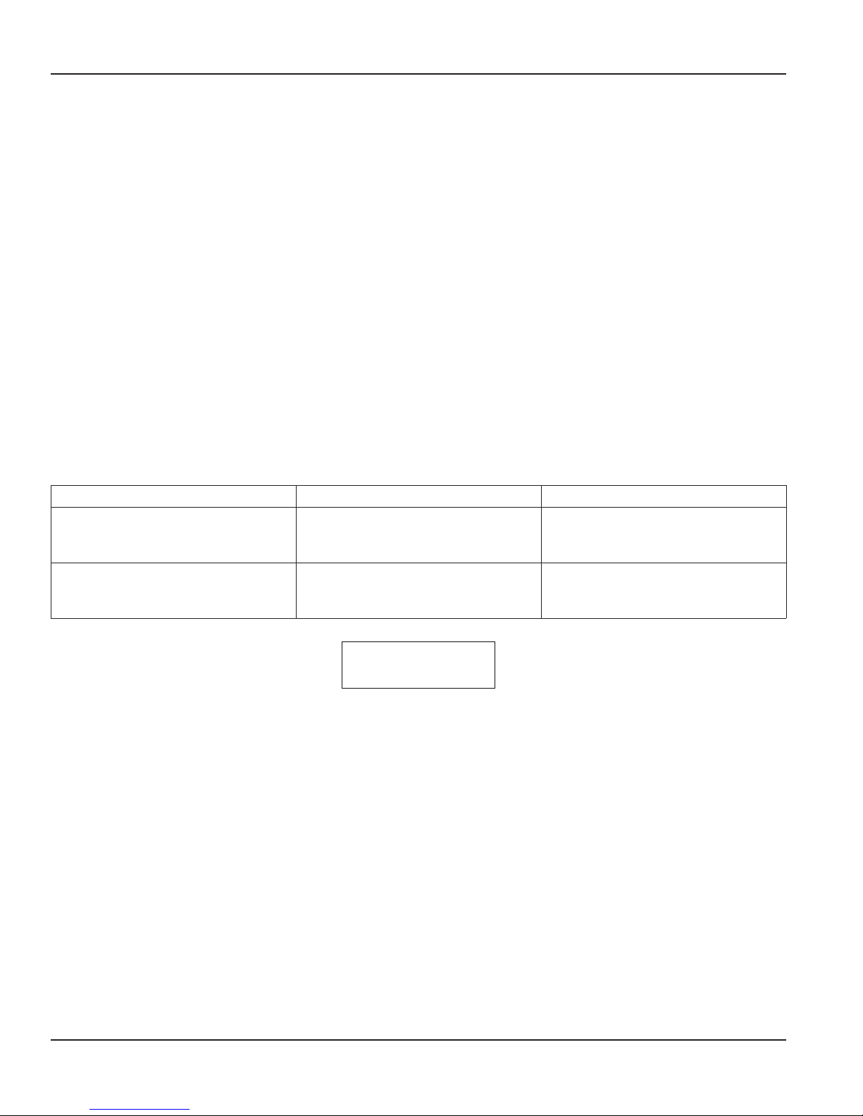
Use the K-Factor Source option to indicate the type of pipe used for flow calculations.
Line Size Use for ASME pipe along with Schedule option. Select the pipe size in Programming Mode Level 1
DN Use for DN pipe. Select the pipe size in Programming Mode Level 1
Pipe ID
K-Factor Entry
Use for non-standard pipes or when the pipe inner diameter (ID) can be measured directly. Enter the pipe
size in Programming Mode Level 1
Use K-Factor only and not pipe dimensions in calculations. When K-Factor Entry is selected, the pipe size
option does not appear in Programming Mode Level 1
Table 8: K-factor source options
K-Factor (Insertion Meter Only)
The K-Factor is used for VN2000 insertion vortex flow meters. The transmitter automatically generates the K-Factor based on
the flow meter model type and bore size.
OTE:N DO NOT change the K-Factor that came with your device without first consulting the factory.
To change the K-Factor, press Left Arrow to move the cursor under the digit to be changed. Press Up Arrow to change the
digit. If the K-Factor does not match the “VN2000 SF” found on the bottom right of your sizing sheet, contact the manufacturer.
Schedule (Insertion Meter Only)
When the K-Factor Source is Line Size, use the Schedule option to select the pipe schedule.
Gas Constant (Gas Only)
Use the Gas Constant option only when the gas has characteristics that require calculations other then the standard formula
for calculating the effects of temperature and pressure on the gas flow rate.
Temperature Calibration
The Temp Calibration option calibrates the internal RTD located in the flow meter body. This is used only for flow meters that
have the Mass Flow Transmitter. The calibration is done at the factory and these settings should NOT be changed unless for
reasons below:
Press Up Arrow to scroll through the options:
• Temp Offset is factory-set and should NOT be changed
• Temp Gain is factory-set and should NOT be changed except to calibrate the operating pressure and temperature in the
steam flow meter.
◊ If the operating internal pressure and temperature of the flow meter must be in-field calibrated, do the following:
• To calibrate to a higher setting, increase the Temp Gain by 10 units at a time until the desired operating pressure
and temperature display on the transmitter
• To calibrate to a lower setting, decrease the Temp Gain by 10 units at a time until the desired operating pressure
and temperature display on the transmitter.
Page 19 June 2017 VRX-UM-02233-EN-02
Page 20
Operating the VN2000 Transmitter
Application
The Application option sets up the flow meter for the desired fluid type and application. The Application is factory-set. The
setting is based on the application fluid type and should NOT be changed. If the incorrect fluid type is selected, please contact
the factory immediately.
Modbus Address
Enter the Modbus RTU address. See the “VN2000 Flow Meters Modbus User Manual.”
Settings
Initially, the meter shows field settings that have been factory-set for your particular application parameters.
This option lets you reset all program settings to factory settings, if required. DO NOT change to factory settings unless
advised to do so by the manufacturer.
Vibration Control
The Vibration Control settings block out unwanted vibration or other frequencies that may affect the flow meter accuracy
or repeatability.
High
The highest vibration control setting helps with no-flow condition and active flow condition. Use in locations
where vibration is present
Medium Good vibration control helps with no-flow condition and active flow. Use this setting for steam and gases
Low Basic vibration control during no-flow condition and active flow. Use this setting for liquids
Off No vibration control activated
\
Table 9: Vibration control settings
Page 20 June 2017VRX-UM-02233-EN-02
Page 21
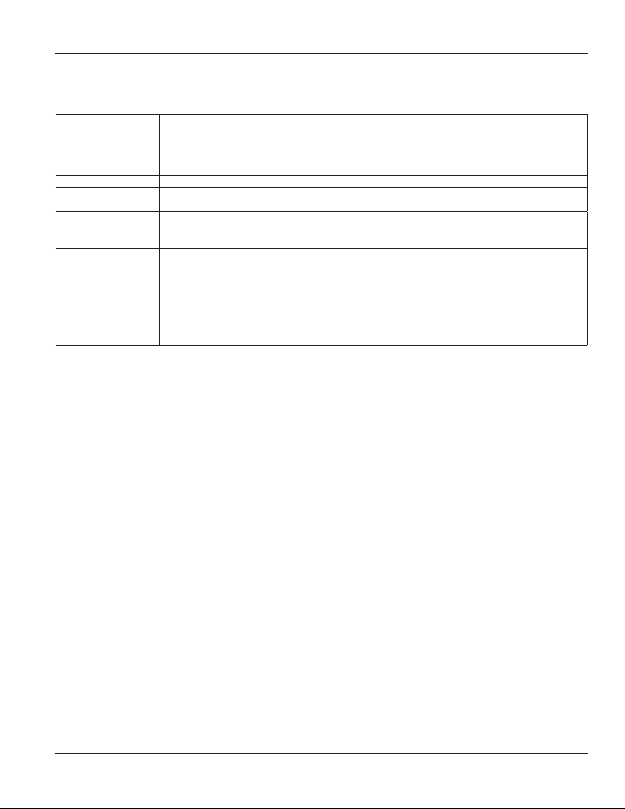
SPECIFICATIONS
2×16 characters reflective display
Display
Keypad 4 membrane buttons
Power 14…36 V DC
Operating
Temperature
Output
Digital Output
Communication EIA-485 with Modbus RTU, 9600 baud
Enclosure General purpose
Mounting Integral meter or remote mount; Up to 30 ft (10 m) from pipe (custom lengths available)
Cable
Rotatable display
Flow rate: 6 digits with decimal
Totalizer
32…140° F (0… 60° C)
5…100% relative humidity non-condensing
One 4…20 mA, 10…36V max load, 24-bit resolution
Adjust the 4 mA and 20 mA signal from the keypad and zero out any anomalies found between the
meter and the monitoring device
One min. input resistance 1000 Ohm
Max output frequency = 12.5 Hz
Opto isolator 5…24V DC
Cable jacket material: polyurethane (gray)
Operating temperature: –13…185° F (–25…85 ° C)
Table 10: Specifications
Specications
Page 21 June 2017 VRX-UM-02233-EN-02
Page 22
Alarm Messages
ALARM MESSAGES
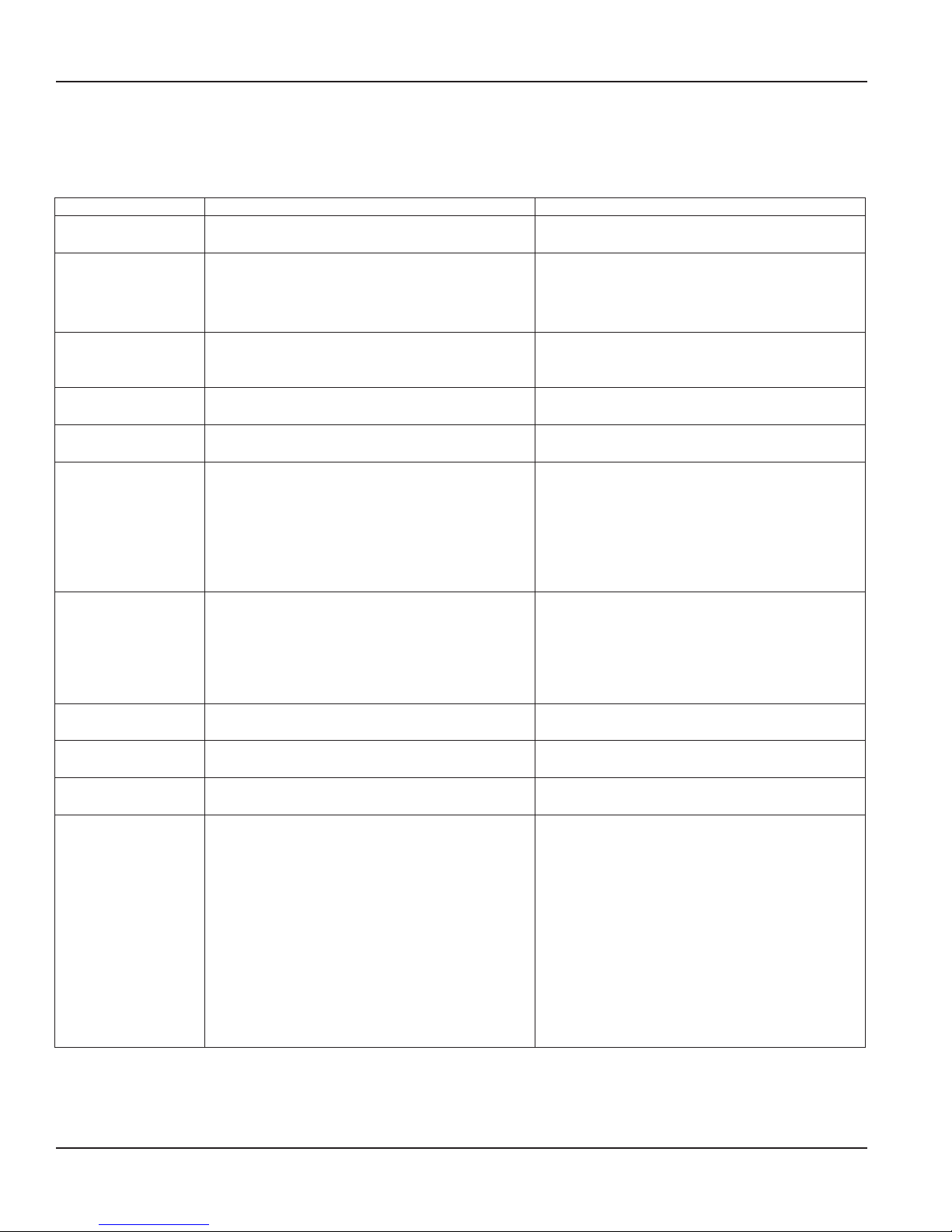
The following alarm messages may appear during operation:
Message Meaning Solution
BAD START MEMORY The flash memory for the system did not load and
a default configuration was assumed.
BAD TEMPERATURE Temperature was out of range. Check the process for very low or very
BELOW LOW FLOW This message indicates that the meter is operating
properly but the flow conditions may be out of
range for your desired operation.
CHECK MAN. PRESS. The manual pressure entry is out of range for the
application.
CHECK MAN. TEMP. The manual temperature entry is out of range for
the application.
CHECK TEMP. This message will display for saturated steam
meters when the temperature in the pipe is below
212° F (100° C). When the temperature inside
the pipe reaches 212° F (100° C) and greater,
this message disappears and flow rate shows
compensated flow rate and total accumulated
flow.
OVER MAX FLOW This message displays when the actual flow rate
has exceeded the max flow (20 mA) setting in
the VN2000 Transmitter representing the 20 mA
output. The flow meter continues to display an
unlimited maximum flow rate. However, the
output stays at 20 mA.
HIGH PULSE RATE The pulse rate is too fast for the hardware. Check PULSE RATE entry and flow rate displayed.
LOW PULSE RATE The pulse rate is too slow for the hardware. Check PULSE RATE entry and flow rate displayed.
NO PRESSURE If the Pressure Sensor is enabled, then the system
was unable to read the sensor.
NO TEMPERATURE If the Temperature Sensor is enabled, then the
system was unable to read the sensor.
Table 11: Alarm messages
Replace the transmitter.
high temperatures.
Check cable connectors for loose connectors or
corrosion
Check the process system for pump or valve
operation if this condition is not expected.
Change the LOW FLOW CUTOFF value, if needed.
Program the manual pressure entry to the correct
value and units.
Program the manual temperature entry to the
correct value and units.
Check the steam system for proper temperature
and operation. If the steam is at 212° F (100° C) or
greater, check the RTD in the meter.
Check the process system for pump or valve
operation, if this condition is not expected.
Change the max flow (20 mA) setting, if needed.
Lower PULSE RATE to a slower setting.
Raise PULSE RATE to a faster setting.
Check that a pressure sensor was included in the
vortex sensor.
Disconnect power.
Check that the sensor included an RTD.
Check cable connectors for loose connectors
or corrosion.
Remove power from the transmitter and open
the transmitter. With an Ohm meter, measure
the resistance between the gray, white and
pink wires.
Gray and white, 0…3 Ohms
Gray and pink, approximately 100 Ohms
White and pink, approximately 100 Ohms
Page 22 June 2017VRX-UM-02233-EN-02
Page 23
Troubleshooting
TROUBLESHOOTING
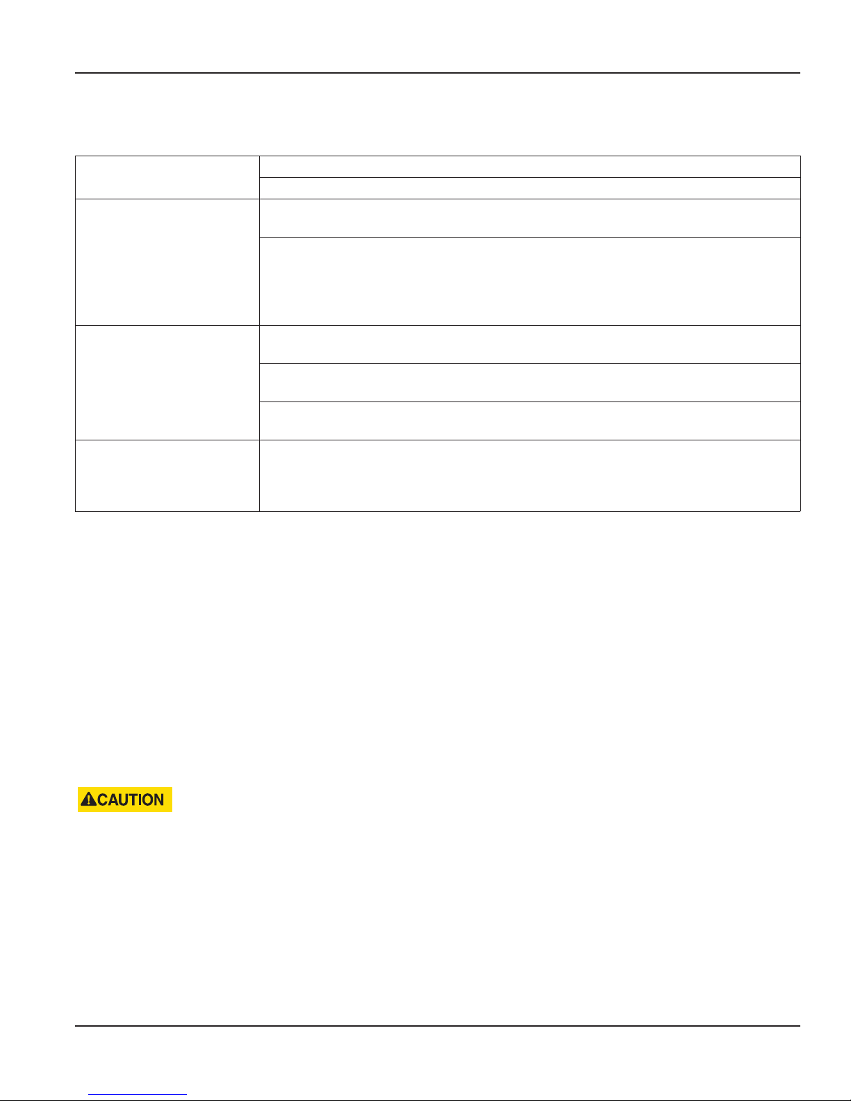
Screen is blank (No display) Verify that you have 24V DC.
Verify that power polarity is correct (Black +24V DC & Blue -24V DC).
Screen shows no flow rate
during flow
Flow rate is erratic Check to see what is installed upstream of the flow meter. Other instruments or devices
Flow rate seems incorrect Review the program settings and make sure the correct line size is chosen for your
Check arrow and alignment hole on the top of the probe. They must be pointing down the
pipe in the direction of flow.
Take a measurement from the top of the stainless steel probe to the top hole in the center
of the pipe. The overall length of the meter from the shedder bar to the hole is XX. The
length of XX minus the length measured is the distance the meter is in the pipe. Make sure
the meter is in the center of the pipe and not sitting inside the valve assembly or close to
the inside wall of the pipe.
before the flow meter can shed vortices of their own causing a disruption in flow reading.
Check to see if there are any valve, tees or elbows upstream of flow meter. If these items are
too close to the flow meter then they can cause disruption in flow reading.
Check to see what size hole is drilled into the pipe for insertion. If an existing hole larger
than 1.5 inch was used, the larger hole can create turbulence directly above the flow sensor.
application. If this is a multi-variable MASS unit, make sure the correct pressure and
temperature is being displayed on the screen. If this is a fixed MASS unit, make sure the
correct operating pressure is entered into the electronics for calculations.
Table 12: Troubleshooting
Transmitters and replacement electronics are available. Please contact the factory for proper selection.
REMOVING VN2000 TRANSMITTER ELECTRONICS
1. Turn OFF power to the transmitter.
2. Remove the enclosure lid.
3. Remove the transmitter electronics:
a. Insert a standard screwdriver under one of the slits along the sides of the case.
b. Carefully put your thumb or finger under the end of the screwdriver
c. Using the end of the screwdriver as a lever, press down on the handle to move the transmitter slowly out of the case.
d. Repeat steps 3a, 3b and 3c for each slit until the case can be pulled out with the fingers.
e. Press down on the connector tab and pull straight out.
DO NOT TO BEND THE CONNECTOR. PULL IT STRAIGHT OUT. DO NOT PUT EXCESSIVE PRESSURE ON THE PLUG BECAUSE
DAMAGE TO THE PLUG OR CONNECTOR ON THE BOARD MAY OCCUR.
Page 23 June 2017 VRX-UM-02233-EN-02
Page 24
North American Pipe Schedules
NORTH AMERICAN PIPE SCHEDULES
Steel, Stainless Steel, PVC Pipe, Standard Classes
NPS
in.
1 1.315
OD
in.
SCH 60 X STG. SCH 80 SCH 100 SCH 120/140 SCH 180
ID
in.
Wall
in.
ID
in.
Wall
in.
ID
in.
Wall
in.
0.957 0.179 0.957 0.179
ID
in.
Wall
in.
ID
in.
Wall
in.
ID
in.
0.815 0.250
Wall
in.
1.25 1.660 1.278 0.191 1.278 0.191 1.160 0.250
1.5 1.900 1.500 0.200 1.500 0.200 1.338 0.281
2 2.375 1.939 0.218 1.939 0.218 1.687 0.344
—
— —
2.5 2.875 2.323 0.276 2.323 0.276 2.125 0.375
3 3.500 2.900 0.300 2.900 0.300 2.624 0.438
3.5 4.000
4 4.500 3.826 0.337 3.826 0.337 3.624 0.438 3.438 0.531
5 5.563 4.813 0.375 4.813 0.375 4.563 0.500 4.313 0.625
—
3.364 0.318 3.364 0.318
— —
—
6 6.625 5.761 0.432 5.761 0.432 5.501 0.562 5.187 0.719
8 8.625 7.813 0.406 7.625 0.500 7.625 0.500 7.437 0.594 7.178 0.719 6.183 1.221
10 10.75 9.750 0.500 9.75 0.500 9.562 0.594 9.312 0.719 9.062 0.844 8.500 1.125
12 12.75 11.626 0.562 11.75 0.500 11.37 0.690 11.06 0.845 10.75 1.000 10.12 1.315
14 14.00 12.814 0.593 13.00 0.500 12.50 0.750 12.31 0.845 11.81 1.095 11.18 1.410
16 16.00 14.688 0.656 15.00 0.500 14.31 0.845 13.93 1.035 13.56 1.220 12.81 1.595
18 18.00 16.564 0.718 17.00 0.500 16.12 0.940 15.68 1.160 15.25 1.375 14.43 1.785
20 20.00 18.376 0.812 19.00 0.500 17.93 1.035 17.43 1.285 17.00 1.500 16.06 1.970
24 24.00 22.126 0.937 23.00 0.500 21.56 1.220 20.93 1.535 20.93 1.535 19.31 2.345
30 30.00
36 36.00 35.00 0.500
42 42.00 41.00 0.500
—
29.00 0.500
— — — —
48 48.00 47.00 0.500
Page 24 June 2017VRX-UM-02233-EN-02
Page 25
Steel, Stainless Steel, PVC Pipe, Standard Classes (continued)
North American Pipe Schedules
SCH 10
(Lt Wall)
ID
in.
Wall
in.
SCH 20 SCH 30 STD SCH 40
ID
in.
Wall
in.
ID
in.
Wall
in.
ID
in.
1.049
Wall
in.
ID
in.
1.049 0.133
Wall
in.
ID
in.
SCH 5
Wall
in.
NPS
in.
OD
in.
1 1.315 1.185 0.065 1.097 0.109
1.25 1.660 1.53 0.065 1.442 0.109 1.380 1.380 0.140
1.5 1.900 1.77 0.065 1.682 0.109 1.610 1.610 0.145
2 2.375 2.245 0.065 2.157 0.109 2.067 2.067 0.154
— —
—
2.5 2.875 2.709 0.083 2.635 0.120 2.469 2.469 0.203
3 3.500 3.334 0.083 3.260 0.120 3.068 3.068 0.216
3.5 4.000 3.834 0.083 3.760 0.120
4 4.500 4.334 0.083 4.260 0.120 4.026 0.237 4.026 0.237
5 5.563 5.345 0.109 5.295 0.134 5.047 0.258 5.047 0.258
— —
3.548 — 3.548 0.226
6 6.625 6.407 0.109 6.357 0.134 6.065 0.280 6.065 0.280
8 8.625 8.407 0.109 8.329 0.148 8.125 0.250 8.071 0.277 7.981 0.322 7.981 0.322
10 10.75 10.482 0.134 10.42 0.165 10.25 0.250 10.13 0.310 10.02 0.365 10.02 0.365
12 12.75 12.42 0.165 12.39 0.180 12.25 0.250 12.09 0.330 12.00 0.375 11.938 0.406
14 14.00
13.50 0.250 13.37 0.315 13.25 0.375 13.25 0.375 13.124 0.438
16 16.00 15.50 0.250 15.37 0.315 15.25 0.375 15.25 0.375 15.000 0.500
18 18.00 17.50 0.250 17.37 0.315 17.12 0.440 17.25 0.375 16.876 0.562
—
20 20.00 19.50 0.250 19.25 0.375 19.25 0.375 19.25 0.375 18.814 0.593
24 24.00 23.50 0.250 23.25 0.375 23.25 0.375 23.25 0.375 22.626 0.687
30 30.00
36 36.00 35.37 0.315 35.00 0.500 35.00 0.500 35.25 0.375 35.25 0.375
42 42.00
—
48 48.00 47.25 0.375 47.25 0.375
29.37 0.315 29.00 0.500 29.00 0.500 29.25 0.375 29.25 0.375
— — —
41.25 0.375 41.25 0.375
Page 25 June 2017 VRX-UM-02233-EN-02
Page 26
North American Pipe Schedules
Copper Tubing, Copper and Brass Pipe, Aluminum
Nominal
Diameter
0.5
0.6250
0.75
1
1.25
1.5.
2
2.5
3
Copper Tubing
in.
in.
K L M K L M
Type Type
OD 0.625 0.625 0.625 0.840
Copper
& Brass
Pipe
in.
Alum.
in.
Nominal
Diameter
in.
OD 3.625 3.625 3.625 4.000
Copper Tubing
in.
Copper
& Brass
Pipe
in.
— 3.5
ID 0.527 0.545 0.569 0.625 ID 3.385 3.425 3.459 3.500
OD 0.750 0.750 0.750
Wall 0.049 0.042 0.030 Wall 0.134 0.110 0.095 0.095 0.250
— — 4
OD 4.125 4.125 4.125 4.500 4.000
ID 0.652 0.666 0.690 ID 3 857 3.905 3.935 3.935 4.000
OD 0.875 0.875 0.875 1.050
Wall 0.065 0.045 0.032 0.114 Wall 0.250
— 4.5
OD
— — — —
ID 0.745 0.785 0.811 0.822 ID 4.500
OD 1.125 1.125 1.125 1.315
Wall 0.065 0.050 0.035 0.127 Wall 0.160 0.125 0.109 0.250 0.063
— 5
OD 5.125 5.125 5.125 5.563 5.000
ID 0.995 1.025 1.055 1.062 ID 4.805 4.875 4.907 5.063 4.874
OD 1.375 1.375 1.375 1.660
Wall 0.065 0.055 0.042 0.146 Wall 0.192 0.140 0.122 0.250 0.063
— 6
OD 6.125 6.125 6.125 6.625 6.000
ID 1.245 1.265 1.291 1.368 ID 5.741 5.845 5.881 6.125 5.874
OD 1.625 1.625 1.625 1.900
Wall 0.072 0.060 0.049 0.150 Wall 0.282 0.078
— 7
OD
7.625 7.000
— — —
ID 1.481 1.505 1.527 1.600 ID 7.062 6.844
OD 2.125 2.125 2.125 2.375
Wall 0.083 0.070 0.058 0.157 Wall 0,271 0.200 0.170 0.313 0.094
— 8
OD 8.125 8.125 8.125 8.625 8 000
ID 1.959 1.985 2.009 2.062 ID 7.583 7.725 7.785 8.000 7.812
OD 2.625 2.625 2.625 2.875 2.500
Wall 0.095 0.080 0.065 0.188 0.050 Wall 0.338 0.250 0.212 0.094 —
10
OD 10.125 10.125 10.125 10 000 —
ID 2.435 2.465 2.495 2.500 2.400 ID 9.449 9.625 9.701 9.812 —
OD 3.125 3.125 3.125 3.500 3.000
Wall 0.109 0.090 0.072 0.219 0.050 Wall 0.405 0.280 0.254 — —
12
OD 12.125 12.125 12.125 — —
ID 2.907 2.945 2.981 3.062 2.900 ID 11.315 11.565 11.617 — —
Alum.
in.
—Wall 0.049 0.040 0.028 0.108 Wall 0.120 0.100 0.083 0.250
5.000
Page 26 June 2017VRX-UM-02233-EN-02
Page 27
Cast Iron Pipe, Standard Classes, 3…20 inch
North American Pipe Schedules
10
12
14
16
18
20
Size
in.
A B C D E F G H
Class
in.
OD 3.80 3.96 3.96 3.96
3
— — — —Wall 0.39 0.42 0.45 0.48
ID 3.02 3.12 3.06 3.00
OD 4.80 5.00 5.00 5.00
4
— — — —Wall 0.42 0.45 0.48 0.52
ID 3.96 4.10 4.04 3.96
OD 6.90 7.10 7.10 7.10 7.22 7.22 7.38 7.38
6
Wall 0.44 0.48 0.51 0.55 0.58 0.61 0.65 0.69
ID 6.02 6.14 6.08 6.00 6.06 6.00 6.08 6.00
OD 9.05 9.05 9.30 9.30 9.42 9.42 9.60 9.60
8
Wall 0.46 0.51 0.56 0.60 0.66 0.66 0.75 0.80
ID 8.13 8.03 8.18 8.10 8.10 8.10 8.10 8.00
OD 11.10 11.10 11.40 11.40 11.60 11.60 11.84 11.84
Wail 0.50 0.57 0.62 0.68 0.74 0.80 0.86 0.92
ID 10.10 9.96 10.16 10.04 10.12 10.00 10.12 10.00
OD 13.20 13.20 13.50 13.50 13.78 13.78 14.08 14.08
Wall 0.54 0.62 0.68 0.75 0.82 0.89 0.97 1.04
ID 12.12 11.96 12.14 12.00 12.14 12.00 12.14 12.00
OD 15.30 15.30 15.65 15.65 15.98 15.98 16.32 16.32
Wall 0.57 0.66 0.74 0.82 0.90 0.99 1.07 1.16
ID 14.16 13.98 14.17 14.01 14.18 14.00 14.18 14.00
OD 17.40 17.40 17.80 17.80 18.16 18.16 18.54 18.54
Wall 0.60 0.70 0.80 0.89 0.98 1.08 1.18 1.27
ID 16.20 16.00 16.20 16.02 16.20 16.00 16.18 16.00
OD 19.50 19.50 19.92 19.92 20.34 20.34 20.78 20.78
Wall 0.64 0.75 0.87 0.96 1.07 1.17 1.28 1.39
ID 18.22 18.00 18.18 18.00 18.20 18.00 18.22 18.00
OD 21.60 21.60 22.06 22.06 22.54 22.54 23.02 23.02
Wall 0.67 0.80 0.92 1.03 1.15 1.27 1.39 1.51
ID 20.26 20.00 20.22 20.00 20.24 20.00 20.24 20.00
Page 27 June 2017 VRX-UM-02233-EN-02
Page 28
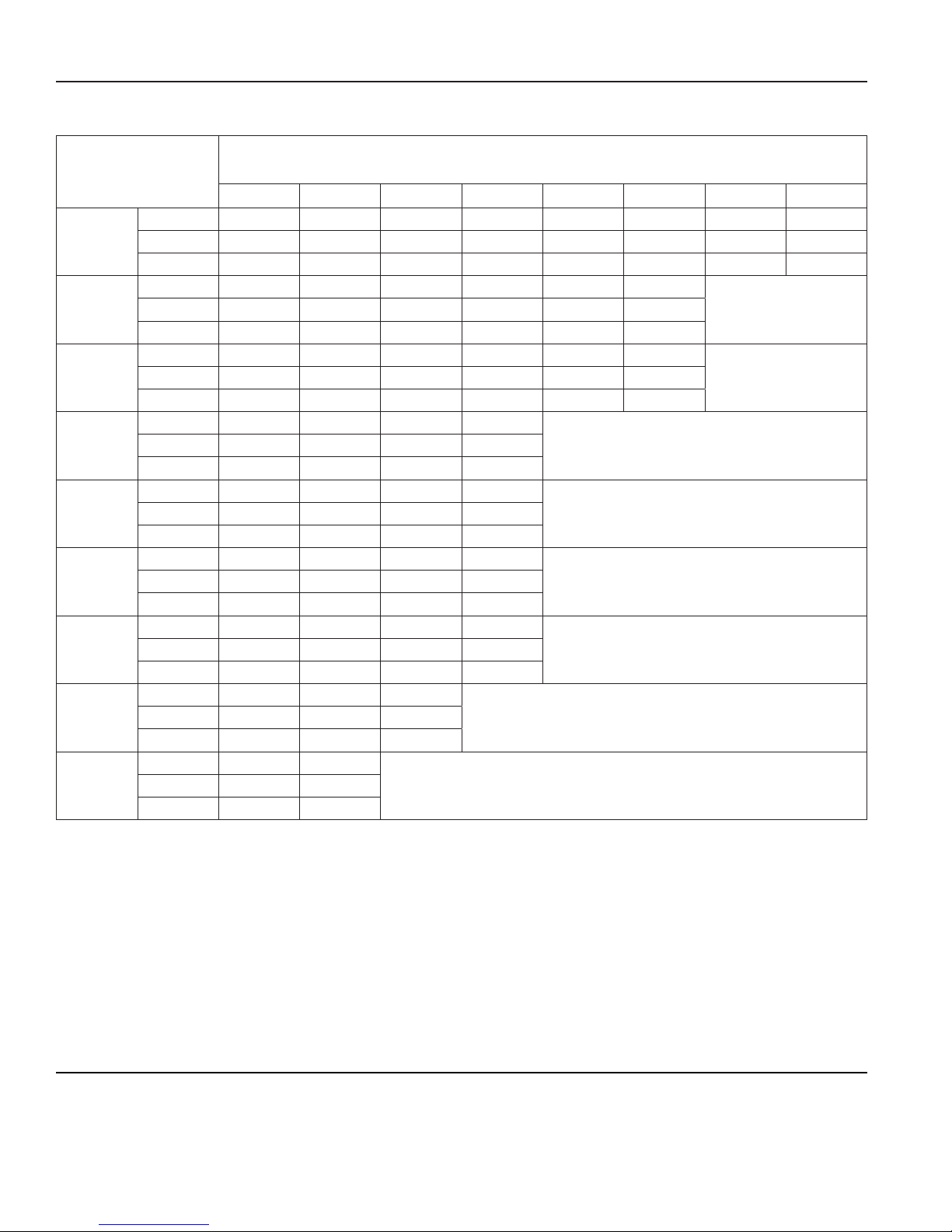
VN2000 Flow Meters, Transmitter
Cast Iron Pipe, Standard Classes, 24…84 inch
24
30
36
42
48
54
60
72
84
Size
in.
OD
Wall
ID
O D
Wall
ID
OD
Wall
ID
OD
Wall
ID
OD
Wall
ID
OD
Wall
ID
OD
Wall
ID
OD
Wall
ID
OD
Wall
ID
Class
in.
A B C D E F G H
25.80 25.80 26.32 26.32 26.90 26.90 27.76 27.76
0.76 0.98 1.05 1.16 1.31 1.45 1.75 1.88
24.28 24.02 24.22 24.00 24.28 24.00 24.26 24.00
31.74 32.00 32.40 32.74 33.10 33.46
0.88 1.03 1.20 1.37 1.55 1.73
—
29.98 29.94 30.00 30.00 30.00 30.00
37.96 38.30 38.70 39.16 39.60 40.04
0.99 1.15 1.36 1.58 1.80 2.02
—
35.98 36.00 35.98 36.00 36.00 36.00
44.20 44.50 45.10 45.58
1.10 1.28 1.54 1.78
—
42.00 41.94 42.02 42.02
50.55 50.80 51.40 51.98
1.26 1.42 1.71 1.99
—
47.98 47.96 47.98 48.00
56.66 57.10 57.80 58.40
1.35 1.55 1.90 2.23
—
53.96 54.00 54.00 53.94
62.80 63.40 64.20 64.28
1.39 1.67 2.00 2.38
—
60.02 60.06 60.20 60.06
75.34 76.00 76.88
1.62 1.95 2.39
—
72.10 72.10 72.10
87.54 88.54
1.72 2.22
—
84.10 84.10
Control. Manage. Optimize.
Trademarks appearing in this document are the property of their respective entities. Due to continuous research, product improvements and enhancements, Badger Meter reserves
the right to change product or system specications without notice, except to the extent an outstanding contractual obligation exists. © 2017 Badger Meter, Inc. All rights reserved.
www.badgermeter.com
The Americas | Badger Meter | 4545 West Brown Deer Rd | PO Box 245036 | Milwaukee, WI 53224-9536 | 800-876-3837 | 414-355-0400
México | Badger Meter de las Americas, S.A. de C.V. | Pedro Luis Ogazón N°32 | Esq. Angelina N°24 | Colonia Guadalupe Inn | CP 01050 | México, DF | México | +52-55-5662-0882
Europe, Eastern Europe Branch Oce (for Poland, Latvia, Lithuania, Estonia, Ukraine, Belarus) | Badger Meter Europe | ul. Korfantego 6 | 44-193 Knurów | Poland | +48-32-236-8787
Europe, Middle East and Africa | Badger Meter Europa GmbH | Nurtinger Str 76 | 72639 Neuen | Germany | +49-7025-9208-0
Europe, Middle East Branch Oce | Badger Meter Europe | PO Box 341442 | Dubai Silicon Oasis, Head Quarter Building, Wing C, Oce #C209 | Dubai / UAE | +971-4-371 2503
Slovakia | Badger Meter Slovakia s.r.o. | Racianska 109/B | 831 02 Bratislava, Slovakia | +421-2-44 63 83 01
Asia Pacic | Badger Meter | 80 Marine Parade Rd | 21-06 Parkway Parade | Singapore 449269 | +65-63464836
China | Badger Meter | 7-1202 | 99 Hangzhong Road | Minhang District | Shanghai | China 201101 | +86-21-5763 5412
Switzerland | Badger Meter Swiss AG | Mittelholzerstrasse 8 | 3006 Bern | Switzerland | +41-31-932 01 11
 Loading...