

Page 1
STORM
3-INCH dredge
All information correct as March 2020 and subject to changes without notification.
Dredge Equipment Operations manual.
PATENTED
Page 2

Index
1.
Cover page
2.
Index
3.
Introduction
4.
Introduction continued
5.
Performance graph with 6cc and 10cc motors
6.
Performance and removal rates
7.
User checklist
8.
User checklist continued
9.
Hydraulics
10.
Hydraulic continued
11.
Installation
12.
Installation continued
13.
Installation continued
14.
Changing hydraulic motors
15.
Shipping box and spares
16.
Inventory
17.
Axial pump repair procedures
18.
Axial pump repair procedures
19.
Trouble shooting
20.
Contacts
Your safety is your responsibility. Please ask if you are unsure about anything.
Page 3

Introduction
The Vortex STORM 3-inch is characterized by the following advantages:
• No depth limitations
• Quick mobilization
• Easy operation
The STORM 3-inch dredge Is designed for higher capacity hydraulic supplies that enable a dredge Inlet vacuum up to 29.5 in/hg (100
kpa) at 206 bar and 39lpm. The Vortex STORM ROV 3-inch is designed for Subsea excavation and disposal of seabed materials up to 75
millimeters in size. It can be mounted to any Work Class ROV and requires no ship deck space and sea fastening. The Vortex STORM
3-inch is very powerful, has no depth limitations and is quick and easy to mobilize and operate.
Dredge must NOT be run in air. Only in water.
The Vortex STORM 3-inch equipment can be operated and maintained by the ROV crew.
Ease of mobilization is key with supplied ROV installation bracket in the kit. The client needs to see rapid deployment of hire gear. The
entire kit is shipped in one single box.
Your safety is your responsibility. Please ask if you are unsure about anything.
Page 4

Introduction continued
Operating Limits
The operating limit for the Vortex STORM 3-inch , will be the responsibility of the Senior ROV person on-site. The limitation
being the ability to safely deploy and recover the ROV system with the Vortex STORM 3-inch attached. Care must be taken whilst during
launch and recovery operations to prevent damage to all components of the dredge system and the ROV.
Risks - Normal Operations
All personnel involved in deck operations shall be aware of the potential risk described hereafter.
• Crane Handling (possible danger of e.g. heavy falling object)
• Launch and recovery of equipment over the side of the vessel
• Personnel working over open sea (typical personnel working with launch and recovery of equipment from vessel
deck or moon pool)
• Object falling down from height (rocks following the equipment when recovering)
• Working with equipment under pressure (hydraulics or water)
• Hydraulic oil spillage
Safety
Personal protection equipment recommended for use when working on ship/platform deck
• Hard Hat
• Safety glasses
• Gloves
• Safety Boots
• Overall
Vortex STORM 3-inch Introduction
The Vortex STORM 3-inch is designed for Subsea excavation and disposal of sediments and gravel up to 75 millimeters. It is easily
mounted to the ROV and requires no ship deck space and sea fastening. The Vortex STORM 3-inch requires no specialist operator or
additional cables between ship and sea floor.
Page 5
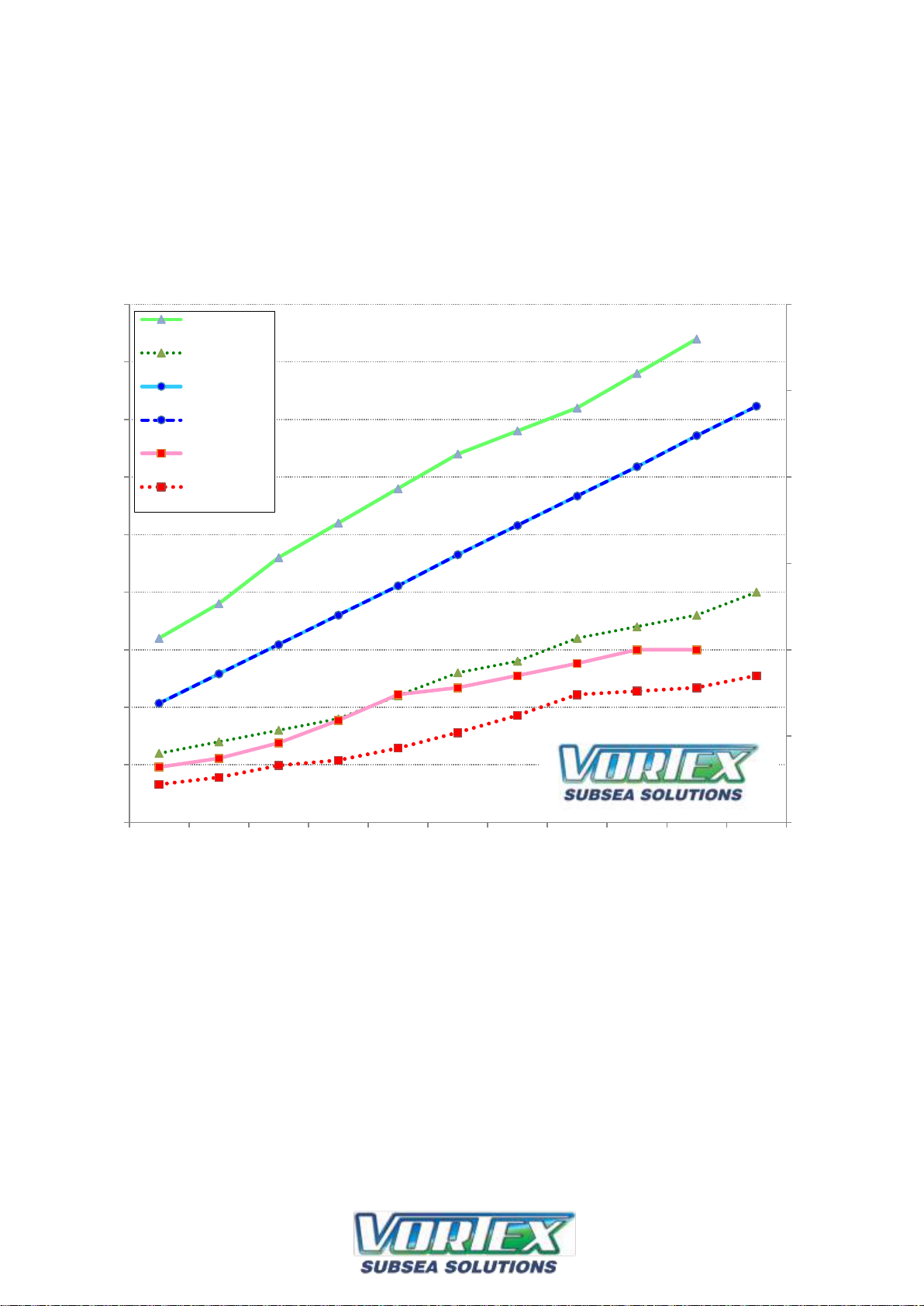
Vortex STORM suction performance.
16 l/min
19 l/min
23 l/min
26 l/min
29 l/min
32 l/min
34 l/min
36 l/min
39 l/min
42 l/min
6 l/min
7 l/min
8 l/min
9 l/min
11 l/min
13 l/min
14 l/min
16 l/min
17 l/min
18 l/min
20 l/min
69 bar
86 bar
103 bar
120 bar
137 bar
155 bar
172 bar
189 bar
206 bar
224 bar
241 bar
32 KPa
37 KPa
46 KPa
59 KPa
74 KPa
78 KPa
85 KPa
92 KPa
100 KPa
100 KPa
22 KPa
26 KPa
33 KPa
36 KPa
43 KPa
52 KPa
62 KPa
74 KPa
76 KPa
78 KPa
85 KPa
0
50
100
150
200
250
300
0
5
10
15
20
25
30
35
40
45
1 2 3 4 5 6 7 8 9 10 11
Inlet Vacuum (KPa) Hudraulic Pressure (Bar)
Hydraulic Flow (l/min)
Test No.
Vortex 6cc and 10cc
STORM 3" dredge
Venturi Test Data
10cc Hydraulic
Flow
6cc Hydraulic
Flow
6cc Hydraulic
Pressure
6cc hydraulic
pressure
10cc Inlet
Vacuum
6cc Inlet
Vacuum
6cc and 10cc motors both
included in kit
Page 6
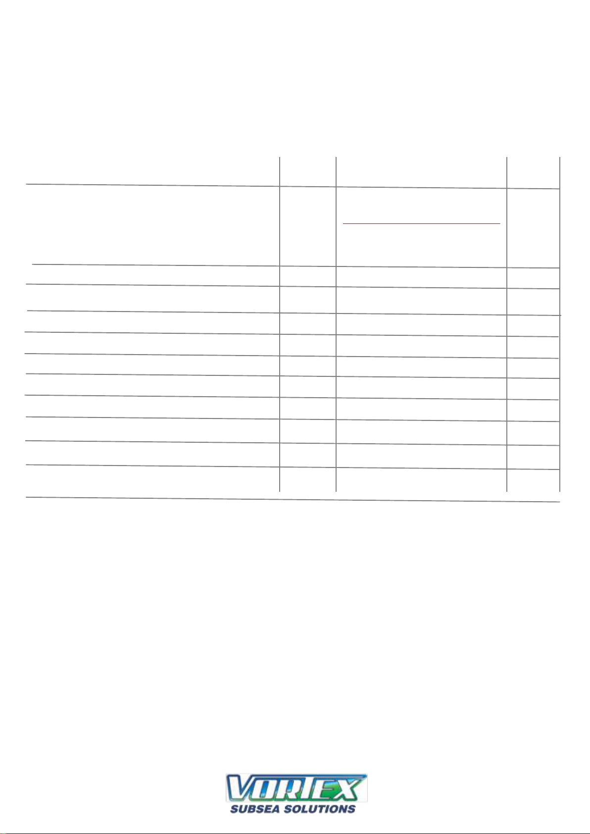
Vortex STORM 3-inch Dredge Capacity
*Based on iron sand and rocks at 2.375 kg per liter
6 cc motor: Debris Removal rates (ton/hr) *22 ton per hour plus
6 cc motor: Debris removal rates (mtr3/ hr) *9 cubic meter per hour *10% solids by volume
10 cc motor: Debris Removal rates (ton/hr) *25 ton per hour plus
10 cc motor: Debris removal rates (mtr3/ hr) *10.5 cubic meter per hour *10% solids by volume
Rated Maximum stone size 75 mm
Actual Maximum stone size 75 mm
Inlet suction hose length 3800 mm standard to custom length
Hydraulic flow required 6 cc motor: 13 lpm minimum (3.4 gpm minimum)
OPTIMUM FLOW IS 17 lpm (4.5 gpm)
10 cc motor: 32 lpm minimum (8.4 gpm minimum)
OPTIMUM FLOW IS 39 lpm (10.3 gpm)
Coupling compensator NO
Hydraulic pressure required 6cc = 155 bar minimum (2250 psi minimum)
10cc = 155 bar minimum (2250 psi minimum)
OPTIMUM PRESSURE IS 3000 psi (206 bar) (4500 psi max)
Operating depths Unrestricted
Operate pump in air NO. DO NOT RUN PUMP IN AIR: ALWAYS RUN IN WATER
Available suction at inlet 6 cc motor: 22.4 in/hg (76 kpa) at 206 bar and 17 lpm
10 cc motor: 29.5 in/hg (100 kpa) at 206 bar and 39 lpm
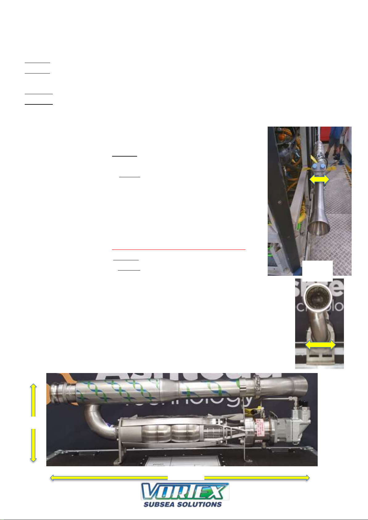
Main Components Weights and Measures
Pump weight in air 32 kg (complete pump unit)
Pump weight in Seawater 24 kg (complete pump unit)
Performance and removal rates
135mm
wide
325mm
1005 mm
Page 7
User Checklist Before Dive
To prevent any damage to the equipment this checklist must be followed
Project: ............................................................................................... Dredge No: ...................................................
Item Description Checked Comments Date
1. Ensure ROV can and does supply optimal hydraulic
flow and pressure.
DO NOT RUN PUMP IN AIR: ALWAYS RUN IN WATER
2. All fittings are checked for leakage
3. All hose clamps are checked
4. Pumps are fastened, no loose screws
5. Suction hose is fastened
6. Dredge is fastened, no loose ends
7. All hoses are fastened and in proper condition
8. Filter for induction is mounted in clean water
9. No hoses are squeezed or bent
10. Inlet nozzle is mounted correctly
11. Case drain and coupling are filled with clean oil
Comments:
.......................................................................................................................................................................................................................
.......................................................................................................................................................................................................................
..........................................................................................................................................................................................................
Dredge is checked by: ............................................................................................
Date: ............................................................................................
TORNADO 4-INCH ROV DREDGE
EQUIPMENT OPERATIONS MANUAL
Page 8

User Checklist Before Dive
To prevent any damage to the equipment this checklist must be followed
Project: ............................................................................................... Dredge No: ...................................................
Item Description Checked Comments Date
1. Equipment used in the sea must be
DO NOT RUN PUMP IN AIR: ALWAYS RUN IN WATER
properly cleaned with fresh water
2. All fittings are checked for leakage
3. All hose clamps are checked
4. Pumps are fastened, no loose screws
5 Suction hose is fastened
6. Dredge is fastened and in proper condition
7 All hoses are fastened and in proper condition
8. No hoses are squeezed or bent
9. Hydraulic motor and coupling is filled with clean oil
10. Broken parts are reported to vortex
Comments: .................................................................................................................................................................................
...........................................................................................................................................................................................
Dredge is checked by: ............................................................................................
Date: ............................................................................................
What were the positives? ...................................................................................................................................................
What were the negatives? ..................................................................................................................................................
Suggestions to make this kit better for you to use in the field:
............................................................................................................................................................
TORNADO 4-INCH ROV DREDGE
EQUIPMENT OPERATIONS MANUAL
POST DIVE:
Ensure all parts subject to sea water are washed down with
fresh water and dried before placing into shipping box.
Page 9

Vortex STORM 3 - inch Hydraulics
DO NOT RUN PUMP IN AIR: ALWAYS RUN IN WATER
Motor / pump Hoses and Connectors
1/2” Pressure Hydraulic Hose - 8 JIC Female fittings 4 mtr long
1/2” Return Hydraulic Hose -8 JIC Female fittings 4 mtr long
3/8” Case Drain Hydraulic Hose -6 JIC Female fittings 4 mtr long
Hydraulic Motor Requirements
Hydraulic flow required 6 cc motor: 13 lpm minimum (3.4 gpm minimum)
OPTIMUM FLOW IS 17 lpm (4.5 gpm)
10 cc motor: 32 lpm minimum (8.4 gpm minimum)
OPTIMUM FLOW IS 39 lpm (10.3 gpm)
Hydraulic pressure required 6cc = 155 bar minimum (2250 psi minimum)
10cc = 155 bar minimum (2250 psi minimum)
OPTIMUM PRESSURE IS 3000 psi (206 bar) (4500 psi max)
Vortex STORM 3 - inch Pump and Motor
The pump must be mounted on the ROV with ample room for both hydraulic and water hose connections.
Hydraulic connections seen at the top. Fill hydraulic motor with clean oil before start up.
Vortex STORM 3 - inch installation to ROV
The dredge is easily fixed to the ROV using supplied aluminum bracket.
Suction Hose and Handle
The suction head comes equipped with a fish-tail style handle for ROV manipulator. Other handle versions can be supplied.
Page 10

Vortex STORM 3 - inch Hydraulics
DO NOT RUN PUMP IN AIR: ALWAYS RUN IN WATER
Hydraulic Schematics
Vortex STORM 3 - inch Hydraulic Hoses
•
Hydraulic hoses for pump/motor connections.
•
Two 4 mtr lengths ½” hoses
•
One 4 mtr length 3/8”
TORNADO 4-INCH ROV DREDGE
EQUIPMENT OPERATIONS MANUAL
Case drain to tank
Pressure and tank return
clearly marked.
Check valve always
remains in place
Page 11

Installation
Dredge shown mounted to ROV
using supplied aluminum angle. Drill
supplied angle to suit.
Page 12

Installation
Exhaust cone can be rotated to
allow dredge to be installed
inside ROV frame and deflect
debris away from the ROV
Loosen clamp here to rotate exhaust cone.
Always double nut and check gasket is in place.
Page 13
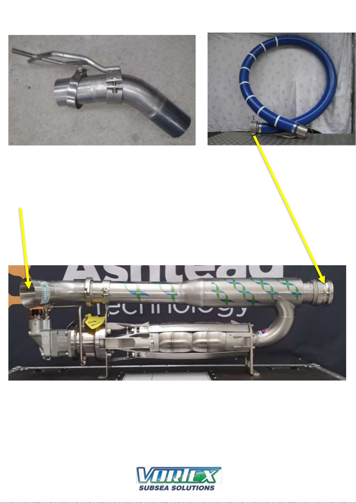
Installation – Hose Connections
Inlet hose with
suction head and
ROV manipulator
handle.
Exhaust
3 inch suction head and ROV
manipulator handle.
Page 14

Operation – Changing hydraulic motors
6 cc motor
10 cc motor
Tri clove O-ring
Pump O-ring
Remove four M12 – Adaptor bolts.
Remove motor.
No O-rings are present or needed.
Slide in new motor.
Secure four M12 – Adaptor bolts.
Torque to 20 Nm
No O-rings are present or needed.
Page 15
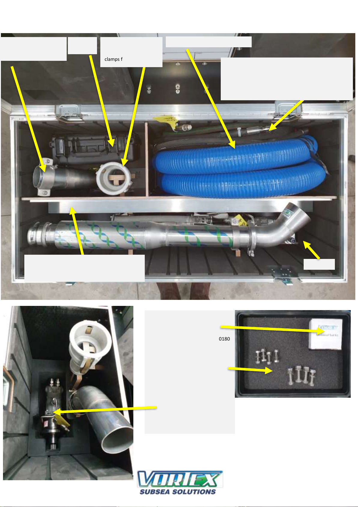
Shipping box placement of components.
3 inch suction nozzle and
manipulator handle. With
45 degree elbow
3 inch female to hose
tail cam lock with three
x 85 to 91mm hose
clamps for suction hose
Spares
kit.
Vortex water pump spares kit.
•
Shaft seal.
•
One x Mech. seal rotor #
10185
One x Mech. seal seat # 10180
•
Four x M10 x 40 bolts, nylocks
and washers to mount
aluminium bracket to ROV.
•
Four x M8 x 30 bolts, nylocks
and washers to mount dredge
to aluminium bracket.
•
Second motor is stored here.
Kit has two motors in total:
One x 10cc motor
One x 6cc motor
3 mtr long 3 inch suction hose
Hydraulic hoses.
•
Two x 4mtr pressure and return hoses with -8 jic
female swivel fittings. 90 degree elbow at one end of
each hose.
•
One x 4mtr case drain hose with -6 jic female swivel
fittings. Straight both ends.
Manuals
9mm x 75mm x 150mm x 1100mm long
alloy Dredge to ROV mounting plate.
Drill to suit your application.
Page 16

TORNADO 4-INCH ROV DREDGE
EQUIPMENT OPERATIONS MANUAL
Inventory
• 3 inch dredge unit
• Two x 4mtr long -8 Jic female swivel P and T hoses (90 degree elbow at one end of each hose)
• One x 4mtr long -6 jic female swivel case drain hose
• 1100 x 75 x 150mm alloy, dredge to ROV mounting plate
• One x 3 inch female camlock with 3 inch hose tail. For suction hose
• Ove x 3 inch stainless tube with 45 degree elbow with ROV manip handle. For suction hose
• One x generic spares kit as shown below
• One x water pump spares kit as shown below
1 x Mech. seal rotor # 10185
1 x Mech. seal seat # 10180
• One x operations manual
• Two hydraulic motors in kit – one fitted on dredge and one store in case.
10 cc motor complete ready to bolt on
6 cc motor complete ready to bolt on.
9mm x 75mm x 150mm x
1100mm long alloy Dredge
to ROV mounting plate.
Drill to suit your
application.
•
117 cm long x 58 cm wide x 74 cm high.
•
140 kg weight
Page 17

Axial pump repair procedures
Mechanical seal replacement:
1. Remove pump suction screen
2. Remove M12 bolts holding aluminium motor adaptor to stainless pump terminal and remove
drive assembly
3. Holding motor in a vice with shaft pointing vertical upwards, unfasten motor cap screws and
remove aluminium adaptor from motor assembly, taking care to avoid contact between seal
stationary seat and shaft surface.
4. Remove circlip and seal seat retainer from motor adaptor. Remove seat and replace with new
item from service kit. Refit retainer in same orientation as when removed and replace circlip.
5. Slide mechanical seal rotor from shaft and fit replacement seal rotor hard back against rear
shoulder of sleeve using light hydraulic oil as a lubricant.
6. Clean both seal face using a lint free cloth and clear gasoline (or equivalent) – lubricate rotor face
with a drop of clean hydraulic oil.
7. Assemble parts in reverse order using torque settings as laid down in torque chart in this
instruction set.
Hydraulic motor replacement:
1. Disassemble unit per steps 1-3 in “Mechanical seal change” instruction
2. Fit plastic protecting sleeve from service kit to shaft spline, holding firmly with vice-grip, and
using a 5mm allen key, remove the shaft retaining cap screw. Using slide hammer with a 12mm
thread remove the shaft from the hydraulic motor.
3. Lubricate the replacement hydraulic motor shaft with a light Moly disulphide paste, refit spacer
and key and slide on the splined stub shaft. If necessary use a hollow drift onto the slide end
shoulder to drive the shaft hard down against the spacer.
4. Clean up the 6mm shaft fastening cap screw and apply a light coating of “BlueMax” or equivalent
silicone sealant to the underside of the head and torque the cap screw to 8 nm.
5. Replace the seal rotor and reassemble the pump set all per steps 4-6 in the “Mechanical seal
replacement” description.
Torque settings:
M6 – shaft retainer cap screw 8nm
M10 – motor retaining cap screw 12nm
M12 – Adaptor bolts 20nm
Page 18
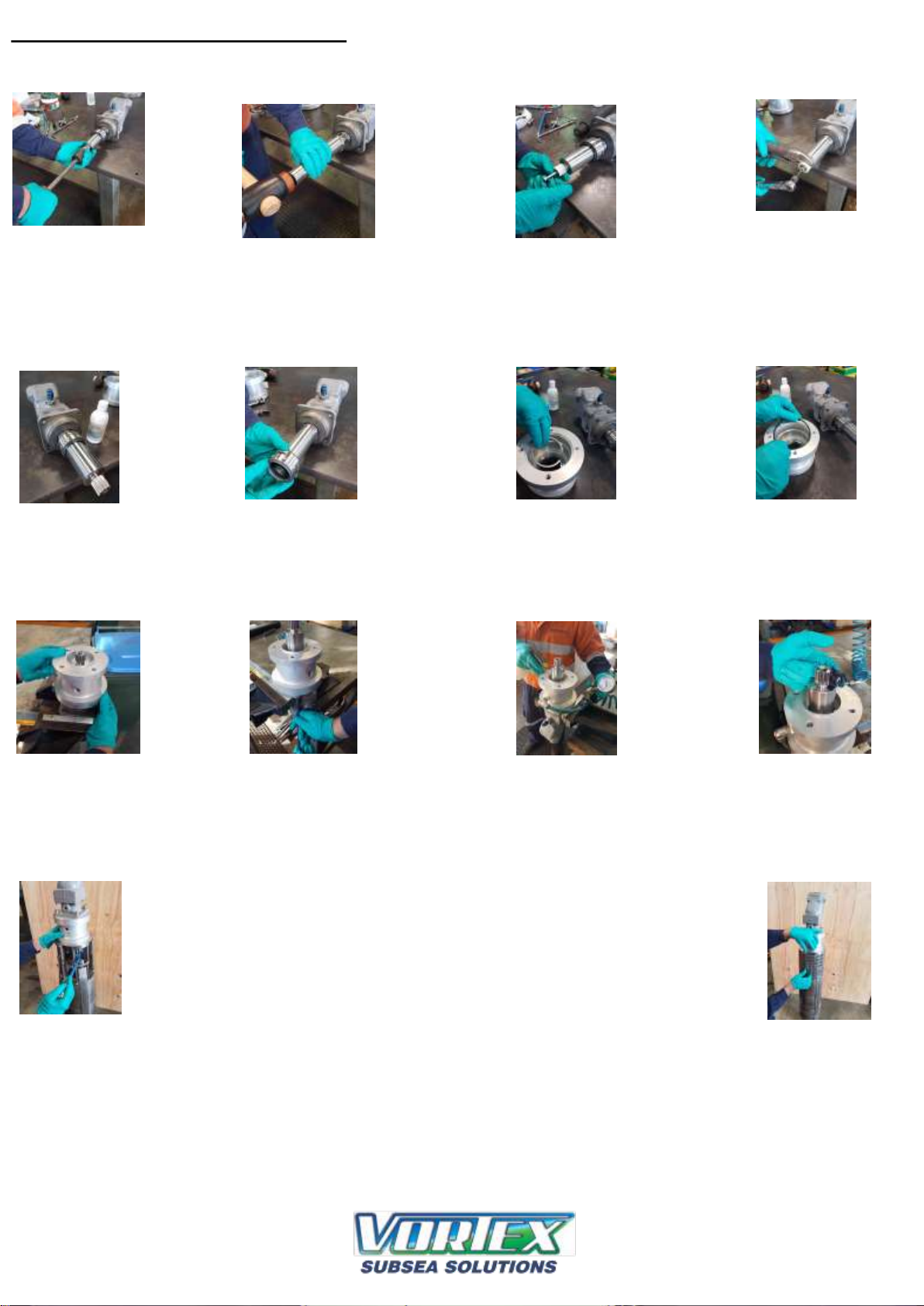
Axial pump repair procedures
Air test mechanical
seal - 20psi
Apply Blue Max ”
or equivalent
silicone sealant to
underside of cap
screw
Apply grease to spline
fit O ring
into
adaptor
recess
fit O-ring - seat retainer ring and
circlip
fit shaft with hollow drift
Push seal onto shaft
with silicone grease
Lubricate shaft
with light
hydraulic oil as a
lubricant
Remove shaft - using
slide hammer if
necessary
Torque sleeve
fastening cap
screw
Slide joint section
to remove screen
from pump
fit adaptor to motor
fasten motor to
adaptor
Fasten pump
affixing cap screws
Page 19

Trouble Shooting
Symptom: Water pump not operating
Remedy:
1. Ensure that the hydraulic hoses are connected as per manual drawings and match connection labels.
2. Check that recommended hydraulic supply can be seen directly at the Vortex water pump hydraulic motor.
3. Check any quick connect fittings you may have in the circuit as they can sometimes be faulty.
4. Are your thrusters using most of the available system flow and starving your circuit feeding the Vortex water pump?
5. Ensure the Vortex case drain is connected directly to tank. It is preferable to connect as close as possible to the
reservoir and not run any hoses through quick connects.
Symptom: Debris removal slow
Remedy:
1. Check the caged nozzle of inlet hose is not blocked. Stop hydraulic flow to water pump to allow rocks and
debris to be cleared.
2. Check that all cam locks are fastened and secured correctly.
3. Check all cam lock O-rings are in place and in good condition.
4. Use steady and consistent movements when plunging suction hose inlet into seabed. Try side to side and up and down
movements of suction hose inlet. Differing conditions may require changing methods.
5. Check all hydraulic remedies as seen in “water pump not operating” section of trouble shooting.
6. Check inlet and exhaust hoses are not bent or blocked.
Page 20

Joe Goodin - Managing Director
VORTEX International Ltd, 27 Parrs Road, RD1, New Plymouth, New Zealand
Tel/Fax: +64 (6) 753 8102, Mobile: + 64 (0) 27 688 5372, Email: joe@vortexdredge.com, www.vortexdredge.com
In association with Ashtead Technology:
ABERDEEN
Ashtead Technology Ltd
Ashtead House, Discovery Drive, ArnhallBusiness Park,
Westhill, Aberdeenshire AB32 6FG
Tel: +44 (0)1224 771888,
Email: aberdeen@ashtead-technology.com
SINGAPORE
Ashtead Technology (S.E.A) Pte Ltd
Loyang Offshore Supply Base, 25 Loyang Crescent, Block 302,
Unit 02-12 TOPS Ave 3, PO Box 5157, SINGAPORE 508988
Tel: +65 6545 9350,
Email: singapore@ashtead-technology.com
HOUSTON
Ashtead Technology Offshore Inc
19407 Park Row, Suite 170, Houston, TX 77084, U.S.A
Tel: +1 281 398 9533,
Email: houston@ashtead-technology.com
SCOPE ENGINEERING
(Ashtead Technology Agent)
Scope Engineering (WA) Pty Ltd
35 Stuart Drive, Henderson, Western Australia 6166
T: +61 8 6498 9642 F: +61 8 6498 9584,
Email: Perth@ashtead-technology.com
Innova AS
P.O. Box 390 Forus, 4067 Stavanger
Phone: +47 51 96 17 00
Fax: +47 51 96 17 01
E-mail: post@innova.no
TES Survey Equipment Services LLC
PO Box 128256
Abu Dhabi
UAE
Tel: + 971 2 650 7710
Fax: +971 2 650 7200
E-mail: info@tesme.com
 Loading...