

Page 1

Installation Instructions
TM
combo-pac
hot water air handler
with high efficiency EC motor and
iStat6 Control
45 Cowansview Rd.
Cambridge, Ontario
N1R 7L2
Phone: 888-781-8151
Fax: 888-670-2544
info@vortexsource.com
www.vortexsource.com
CP-1605
Page 2

CP-1605
Page 3

Table of Contents
TYPICAL PLUMBING CONNECTIONS .......................................................................................................... 5
ELECTRICAL WIRING DIAGRAM .................................................................................................................. 7
INTRODUCTION ............................................................................................................................................ 10
HOW IT WORKS ........................................................................................................................................... 11
COOLING.......................................................................................................................................................... 11
HEATING .......................................................................................................................................................... 11
CONTINUOUS FAN ............................................................................................................................................ 11
PRODUCT DESCRIPTION ............................................................................................................................ 11
CABINET .......................................................................................................................................................... 11
HEATING COILS ................................................................................................................................................ 12
FAN AND MOTOR .............................................................................................................................................. 12
CIRCULATING PUMP .......................................................................................................................................... 12
CHECK VALVE .................................................................................................................................................. 12
CONNECTING TO A WATER HEATER ................................................................................................................... 12
CONNECTING TO A BOILER ................................................................................................................................ 12
EQUIPMENT SELECTION AND SIZING ...................................................................................................... 13
HEAT LOSS ...................................................................................................................................................... 13
AIR HANDLER SELECTION ................................................................................................................................. 13
DUCT LAYOUT .................................................................................................................................................. 13
PLUMBING LAYOUT ........................................................................................................................................... 14
INSTALLATION ............................................................................................................................................. 14
AIR HANDLER MOUNTING .................................................................................................................................. 15
DUCTWORK ...................................................................................................................................................... 15
RISK OF FREEZING ........................................................................................................................................... 16
ELECTRICAL ................................................................................................................................................ 16
THERMOSTAT ................................................................................................................................................... 16
A/C CONDENSING UNIT .................................................................................................................................... 17
START-UP PROCEDURES........................................................................................................................... 17
SERVICE AND MAINTENANCE ................................................................................................................... 19
TROUBLESHOOTING ................................................................................................................................... 20
REFER TO THE CONTROLS MANUAL AS WELL. ..................................................................................................... 20
THERMOSTAT CALL ERROR ............................................................................................................................... 20
PUMP DOES NOT RUN ........................................................................................................................................ 20
PUMP IS NOISY AT START-UP ............................................................................................................................. 20
WATER HEATER T&P IS WEEPING ...................................................................................................................... 20
INSUFFICIENT OR NO HEAT ................................................................................................................................ 20
COLD WATER AT HOT FAUCET ............................................................................................................................ 21
FAN RUNS FOR COOLING BUT NOT HEATING ........................................................................................................ 21
HEATING DURING STANDBY MODE ..................................................................................................................... 21
combo-pac AIR HANDLER PARTS & ACCESSORY LIST ........................................................................ 22
PRODUCT WARRANTY ............................................................................................................................... 23
CP-1605
Page 4

Important notes For the Installer
A Quick Check List
Are the water connections to the water heater oriented in a way to
avoid trapping air in the heating circuit? (see diagram on next page)
Is the purge valve installed on the return line from the air handler
upstream from the isolation valve?
Is the air handler hung and isolated to avoid transmitting vibration
through framing and duct work? Or is the air handler on a
housekeeping pad?
Are the isolation valves full-port? Restrictive valves will limit
performance.
Are Thermostat connections correct, including cooling and continuous
run connections?
Have the packing materials been removed from the blower and the
pump ?
Is there an installation manual for the home owner ?
Is the unit accessible? Are there clearances for service and component
replacement?
Are the supply plenum and return duct/drop acoustically lined ? (at
least 6ft. of the return duct/drop and the supply plenum are
recommended)
Is the filter cover in place? Is a clean filter in place? Is the supplied
filter rack installed?
CP-1605
Page 5
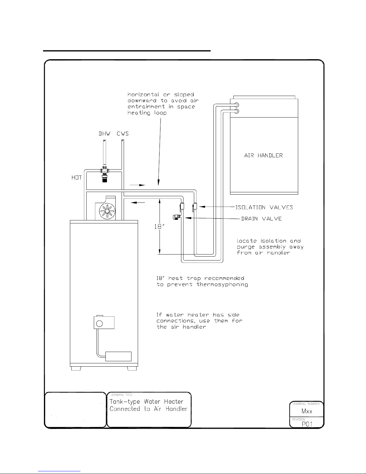
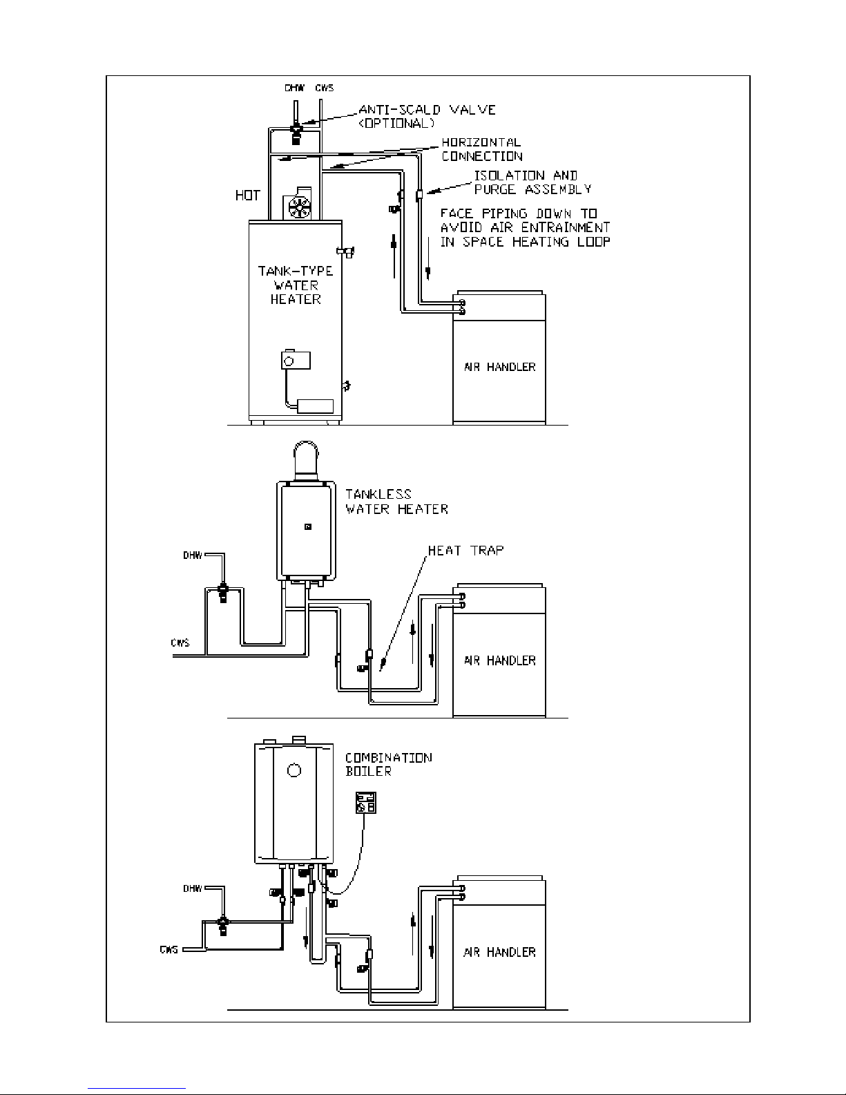
TYPICAL PLUMBING CONNECTIONS
CP-1605
Page 6
CP-1605
Page 7
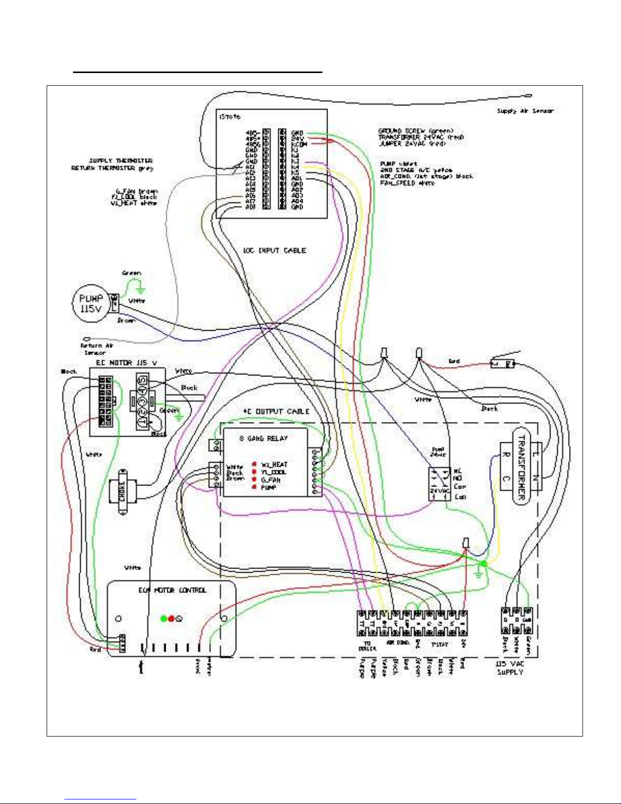
ELECTRICAL WIRING DIAGRAM
Motor choke required for 3/4hp only
CP-1605
Page 8

Physical Properties
Cabinet dimensions Supply air Return air
Model Type
CP30
CP63, CP70,
CP80
CP100
A
depth B width C height
d x e f x g
20” 14” 24” 12”x16” 14”x18” 1/2” 80 lb.
22” 25” 31.5” 20”x20” 18”x23” 3/4” 110 lb.
22” 25” 53.5” 20”x20” 18”x23” 1” 120 lb.
water
inlet
and
outlet
Unit Specifications: combo-pac ECTM air handlers
MODEL: CP30-EC CP63-EC CP70-EC CP80-EC
*Heating Capacity (Btu/h) 120F water
*Heating Capacity (Btu/h) 130F water
*Heating Capacity (Btu/h) 140F water
*Heating Capacity (Btu/h) 160F water
*Heating Capacity (Btu/h) 180F water
(USGPM) Heating
Maximum Heating Airflow (CFM)
Max. External Static Pressure (“wc)**
Max. Cooling Capacity (Tons)
Blower Motor Full Load (Amps)
Circulator Full Load (Amps)
* Based on 70F return air and high fan speed. Contact Vortex for performance at lower water
temperatures.
** Air handler can deliver maximum programmed airflow at any static pressure below this value.
21,000 45,000 51,000 59,000 76,000
28,000 58,000 65,000 73,000 91,000
30,000 63,000 70,000 80,000 106,000
37,000 80,000 90,000 103,000 135,000
48,000 99,000 110,000 125,000 164,000
3.0 4.8 4.8 4.8 7.0
800 1200 1400 1800 2000
1.2 0.6 1.1 0.7 1.0
2.0 3.0 3.5 5.0 5.0
5.5 5.5 7.7 9.6 9.6
0.6 0.8 0.8 0.8 0.8
CP100-EC
Shipping
Weight
CP-1605
Page 9

Unit Specifications: combo-pacTM air handlers with small-D
TM
MODEL
Number of 4”
outlets1
Cooling Capacity
(Tons)
Heating Capacity
(MBH) 130F water3
Heating Capacity
(MBH) 140F water3
Heating Capacity
(MBH) 160F water3
Heating Capacity
(MBH) 180F water3
(USGPM) Heating
Max. Heating
Airflow2
Max. ESP (in.WC)
Blower Motor Full
Load (Amps)
Circulator Full
Load (Amps)
1. Minimum number of outlets required at rated airflow. Refer to SmallD Design for options.
2. These are example air flows and ESP based on number of outlets and programmed
heating/cooling speed. Higher ESPs are available at lower airflows. Contact Vortex for
performance at lower speeds.
3. Based on 70F return air. Contact Vortex for performance at lower water temperatures.
CP30 CP30 CP63 CP63 CP70 CP70 CP80 CP80 CP100 CP100
5
1.5
7 8 10 9 12 12 17 15 20
2.0 2.0 2.5 2.5 3.5 4.0 5.0 4.0 5.0
24 28 48 58 56 65 66 73 77 91
26 30 51 63 60 70 73 80 90 106
32 37 65 81 76 90 94 103 115 135
41 48 81 100 93 110 114 125 139 164
3.0 3.0 4.8 4.8 4.8 4.8 4.8 4.8 7.0 7.0
600 800 900 1200 1050 1400 1350 1800 1350 1800
2
2.3 0.9 1.5 0.6 1.8 1.1 1.8 0.7 1.8 0.6
5.5 5.5 5.5 5.5 7.7 7.7 9.6 9.6 9.6 9.6
0.8 0.8 0.8 0.8 0.8 0.8 0.8 0.8 0.8 0.8
CP-1605
Page 10

INTRODUCTION
combo-pac ™ air handlers are state-of-
the-art units designed for use with
hydronic (boiler) systems or in
combination space and water heating
systems (Combo Systems). Two key
features include automatic heating
capacity adjustment and automatic
cooling dehumidification adjustment.
The programmable control allows for
customization and adjustment of air
speeds and capacity. Combo heating
systems use the home’s water heater to
provide both the space heating and
domestic hot water, eliminating the need
for a furnace.
Combo heating systems are ideally
suited for single-family homes,
townhouses and apartments where the
cost of a furnace does not make sense or
space requirements are limited. They
are also great for additions, renovation
and finished basements as a
replacement for, or in addition to the
existing heating system. Vortex air
handlers are also great for hydronic
heating systems using ground-source
heat pumps. They are the smallest units
available in their capacity range.
combo-pac ™ air handlers are designed
to take the guesswork out of system
sizing and installation. Matched
specifically to common water heater
sizes, Vortex air handlers can be quickly
sized using the quick sizing information
in our spec sheets or from air handler
performance curves. For applications
requiring special consideration, call
888-781-8151 for answers to questions
related to sizing, installation or troubleshooting for any of Vortex air handlers.
Vortex provides you with the quietest
operating air handler available. By using
large capacity, high output heating coils,
these air handlers deliver more heating
per volume of air, which means warmer
delivered air temperatures.
combo-pac™ air handlers are intended
for conventional and small-D™ duct
systems with higher operating static
pressure. Refer to the small-D™ design
manual for more details on duct design
and installation.
CP-1605
Page 11

HOW IT WORKS
The key to the combo-pac ™ system is
the level of comfort provided by the
unique control system. The features
described are adjustable by the installer.
Refer to the control instructions for
details.
Cooling
In automatic mode, a call for cooling will
adjust fan speed according to the
measured humidity. During periods of
high humidity, the fan will slow down and
more humidity is removed from the air.
During drier conditions, the fan runs
faster and removes less humidity.
Measurements and adjustments are
made continuously.
Fixed fan speed is a programmable
option.
There is also an adjustable pre-cooling
and post-cooling feature to reduce fan
speed for improved efficiency and
comfort.
Heating
In automatic mode, the fan will run at a
low level. If the thermostat is not
satisfied within 15 minutes (adjustable),
the fan will speed up every minute until
the thermostat is satisfied or the fan
reaches full speed. The controller
“learns”, so that for the next heating call,
the fan will speed up if the last heating
call was too long or the fan will slow
down if the last heating call was too
short.
Fixed fan speed is a programmable
option.
There is also an adjustable pre-heating
and post-heating feature to reduce fan
speed for improved efficiency and
comfort.
Continuous Fan
When the thermostat fan switch is set to
continuous fan, the fan will run at the
programmed speed (default is 50% of
maximum). When there is a call for
heating or cooling, the normal heating or
cooling speed will over-ride the
continuous fan setting. Once the
thermostat is satisfied, continuous fan
speed will resume.
PRODUCT DESCRIPTION
Cabinet
All cabinets have a tough, durable low
maintenance pre-painted finish.
Cabinet dimensions are designed to
provide maximum installation flexibility.
Refer to installation requirements for
more details.
CP-1605
Page 12

Heating Coils
valve size
Maximum
All heating coils are potable water grade
copper suitable for use in plumbing
systems. No lead solder is used in any
component construction. All coils and
internal piping conform to ASTM B68 or
ASTM B88 standards.
High-density aluminum fins provide
maximum heat transfer for small coil
surface.
Fan and Motor
All fans are wide body dynamically
balanced for extra quiet operation.
Multi-directional sleeve bearing motors
allow mounting in any direction for
maximum installation flexibility.
Circulating Pump
The circulating pump is matched for
maximum performance. Air handlers
come with internally mounted pumps for
ease of installation. Air handlers can be
special ordered with external, field
installed pumps, when it is desirable to
locate the circulator below the air
handler, such as in attic installations.
Check Valve
Check valves serve two purposes:
• protect against back-flow of water to
avoid short circuiting around the
water heater during domestic water
use.
• protect against thermal siphoning.
Thermal siphoning is flow of water
through the space heating circuit while
the circulating pump is not operating due
to hot water rising by natural convection.
During summer months this will cause
overheating, interfere with air
conditioning and waste energy.
All air systems come supplied with spring
loaded, vertical lift check valves. These
check-valves have been tested and
proven to resist thermal siphoning for
installations where the air handler
elevation does not exceed the distance
above the water heater shown in the
table below.
Check Valves
elevation
1/2”(12mm) 25 feet(8 metres)
3/4”(20mm) 50 feet(15 metres)
Connecting to a Water Heater
Any properly sized gas, propane or oil
fired water heater will work in a combo
heating system. Make sure the water
heater being used is approved for combo
applications. (Most manufacturers’
heaters are approved.) Tank-less water
heaters may reduce the capacity of air
handlers due to the higher internal
pressure drop. (Call Vortex for details)
Connecting to a Boiler
All air handlers are compatible for use
with boilers. Standard drawings are
available from Vortex for most boiler
applications.
CP-1605
Page 13

EQUIPMENT SELECTION AND SIZING
Proper sizing of system components is
crucial for proper operation.
Steps for sizing and selection:
1) Obtain room by room heat loss and/or
heat gain
2) Determine heating water temperature
3) Select air handler from specification
sheet
5) Determine duct layout
Heat Loss
Make sure a proper room-by-room heat
loss and heat gain for the dwelling is
calculated using HRAI, ASHRAE or other
approved sizing method.
Air Handler Selection
Select the desired air system that will
meet 100%-140% of the heating load
and 80%-120% of the cooling load.
If using a boiler system, select a boiler
that has an output that meets or exceeds
the heat loss of the space being heated.
If the boiler is meeting additional loads,
size the boiler to meet the total combined
load.
For combo heating systems, use an
approved sizing method such as the
Unified Combo Guidelines published by
HRAI. In areas where the UCG or a local
sizing code is not applicable, use the
following method for sizing combo
systems:
1) Select an air handler that meets or
exceeds the calculated heat loss at the
water heater operating temperature
(130F/55C or 140F/60C).
2) Select a water heater with an output
that is at least 120% of the heat loss
Duct Layout
Make sure a proper duct design has
been completed for the dwelling using
HRAI, ASHRAE or other approved
design method.
Supply air Plenum
Provide a supply air plenum that is the
same dimensions as the outlet flanges of
the air handler. A length of 36 inches is
recommended. Acoustic lining is
recommended.
A smooth, square-to-round transition
may be used in place of the supply air
plenum for horizontal installations where
there is only one supply main.
For vertical applications where the air
conditioning coil is installed in the supply
air plenum, the cooling coil must be
supported at least 4 inches (100mm)
above the heating coil face on brackets
or channel to ensure unimpeded airflow
through the heating coil.
Plenum takeoffs may be mounted on the
end of the plenum or the sides of the
plenum, but not both. Spin-in collars or
transition takeoffs may be used, but not
both.
Supply mains
Plan duct layout to avoid branch runs in
outside walls or attics and to minimize
the length of the main duct
CP-1605
Page 14

Where practical, provide parallel main
ducts to various floors or zones rather
than running a single larger duct with
tees. For applications with 3 or more
floors or any application where a large
seasonal adjustment in airflow is
anticipated, provide parallel supplies with
volume dampers accessible for seasonal
adjustments. For example; a 4-storey
townhouse will probably require vastly
different airflow rates for the upper floors
between cooling and heating seasons. If
there are two main supply trunks, the
supply trunk serving the upper 2 floors
can be damped down in the heating
season to better balance the air flows.
Supply mains may be round duct or
equivalent rectangular duct.
Round duct can be spiral duct, welded or
snap lock seams.
Rectangular duct must be at least 26
gauge for all dimensions. The aspect
ratio for square ducts (wide dimension
over short dimension) shall not exceed
2.5 to1.
Return air duct
The return air duct should be sized for a
total pressure drop of not more than
0.15”w.c. Using conventional sizing
methods and installed in accordance with
HRAI guidelines or equal. It is
recommended that the return air duct or
drop be acoustically insulated for at least
6 feet nearest the air handler. For noise
attenuation, at least 2 changes in
direction over the total return air duct
system is recommended.
Refer to the small-D™ design guide for
additional requirements for small
diameter/higher static duct applications.
Plumbing Layout
Refer to the plumbing diagrams as a
guideline.
Any suitable hydronic pipe is acceptable
for use with the air handler. Do not
exceed 150 psi or 180F (82C). The
boiler, piping or other components may
have more restrictive ratings. If
connecting to a water heater, all
plumbing and components must meet
local plumbing code requirements.
Size piping to match air handler sizing.
Increase one pipe size if distance from
boiler or water exceeds 25ft. or size pipe
according to an accepted design method.
For boiler systems, include expansion
tank, pressure relief valve, pressure
gauge and a suitable fill system. Some
of these may be included in the boiler.
Include drains at system low points and
manual air vents at high points as
required. A temperature gauge near the
inlet to the air handler inlet is
recommended but not required.
15psi is the minimum recommended
design pressure for proper pump
operation. Higher pressure may be
necessary for systems of significant
elevation e.g. basement to attic.
INSTALLATION
CP-1605
Page 15

The installer must adhere strictly to all
local and national code requirements
pertaining to the installation of this
equipment.
Detailed instructions are shipped with all
accessory items and should be followed
in detail.
Air Handler Mounting
The air handler can be installed in any
direction. Its compact dimensions even
allows for installation between joists. The
air handler can be floor mounted or hung
from straps. Some precautions must be
observed for some of the possible
mounting positions.
For installations where the access door
faces up or down, select an air handler
with an external pump to avoid the pump
being mounted with its shaft vertical. The
pump shaft must be mounted horizontally
to avoid premature failure.
The air handler can be hung by securing
straps through any of the existing screw
holes in the cabinet. When the existing
screw is too short for securing a
mounting strap, a longer screw can be
used provided care is taken not to
damage any internal components.
When fastening straps using screws
other than those supplied with the
cabinet, special care should be taken in
the vicinity of the coil to avoid tube
puncture.
Warning!: Do not put screws into the
cabinet directly in front of and behind
the coil.
3/4” screws can be safely installed on
either side of the coil.
The cabinet is designed so that the
return air can be located on either side of
the cabinet, through the bottom of the
cabinet, or from the back. Position the
filter rack so that the filter is readily
accessible.
Install the air handler with the door firmly
screwed in place to make sure the
cabinet remains square.
Provide at least 2 feet (0.75 metres) of
service clearance in front of the access
panel of the air handler. Zero clearance
is acceptable on all other faces.
For vertical installations with a cased
cooling coil on the return, install air
handler on a minimum 2” (50mm)
housekeeping pad to allow room for
minimum 2” trap in the condensate drain.
This trap is necessary to prevent air
leakage through the drain. Refer to the
cased cooling coil installation manual for
more details.
Ductwork
General
Ductwork installed in unheated spaces
such as attics must be installed between
the insulation and the heated space.
Provide at least R-12 of insulation above
ducts. If cooling is required, the branch
and trunk lines must be insulated and
sealed with a vapour barrier prior to
applying house insulation.
If a fresh air duct is required, make
connection to return air plenum at least 6
feet (2m) upstream from filter. Insulate all
fresh air ducts.
Supply Ductwork
CP-1605
Page 16

Supply trunks may be square or round.
SEAL all joints and seams with metal
tape or sealing compound. Volume
dampers for each of the main supply
trunks must be accessible for balancing.
(Near the supply plenum is preferred)
Locate outlets at least 6 inches (150mm)
from outside walls or window coverings.
Return Ductwork
Return air plenum should be the same
cross sectional area as the air handler
return air opening. In vertical
installations, a conventional return air
drop and elbow is acceptable. It is
recommended that the return duct /drop
be acoustically lined for 6 feet (2m)
nearest the air handler.
Risk of Freezing
Steps must be taken to prevent the hot
water coil from freezing. Coils that have
failed due to freezing and damage
caused by frozen coils are not covered
under warranty.
HRV and Fresh air connections
Fresh air and HRV connections to
ductwork can pose a risk of dumping cold
air into ductwork during periods of standby or continuous run. Calculate mixed
air stream temperatures and provide
interlock controls to prevent freezing
conditions.
Evaporator coils
Evaporator cooling coils that are
mounted above the hot water coil pose a
risk to the hot water coil in the event that
the compressor contactor on the
condenser sticks in the on position.
When the call for cooling is satisfied, the
blower will stop running and allow cold
air from the evaporator coil to fall onto
the hot water coil.
Attic and crawl spaces
Air handlers may be located in areas
subject to freezing conditions. It is
necessary to protect the hot water coil
and condensate drain from freezing.
Condensate traps should be installed in
the heated space. Give consideration to
insulating the air handler or installing it
into a small, insulated mechanical room.
Consideration can also be given to an
isolating heat exchanger and anti-freeze.
ELECTRICAL
Warning! - Make sure unit is properly
grounded. Locate air handler on a
separate electric circuit, or use the same
circuit as the water heater or boiler where
permitted.
Air handler wiring diagrams are located
on the blower or door for easy reference
during installation and servicing.
Nameplate data is located on the side of
the unit.
All air handlers operate on
115VAC/1ph/60hz line voltage. All
control circuits are 24 VAC. One leg of
the 24 VAC is grounded to the chassis.
Thermostat
CP-1605
Page 17

combo-pac ™ air handlers are
compatible with most standard heat/cool,
heat pump, “electric heat”, “gas heat”,
set-back or electronic thermostat. Some
electronic thermostats (primarily “power
robbing” types) require the addition of a
resistor between the W & C terminals
and the Y & C terminals. This is usually
covered in the thermostat instruction
manual. A 1,000 ohm, 5 watt resistor on
each of the W and Y terminals will
usually be enough to drain the current
required to power the thermostat. Some
thermostats will need 250 ohm, 10 watt
resistors on each of the W and Y
terminals. For two-stage thermostats,
contact Vortex.
Heat Anticipator Setting
For optimum comfort the anticipator
setting should be set to provide
approximately 4 cycles per hour
Typical Heat
Anticipator Setting
0.25 amps
Thermostat wire from the thermostat is
connected to screw terminals located
inside the air handler. The thermostat
should be connected as follows:
R – power (24vac)
W – heating
Y– cooling (if present)
G – continuous run fan
C -- ground
Connect the thermostat to the
appropriate screw terminal.
.
Boiler
The screw terminals labeled TT are dry
contacts for connection to a boiler or
external pump. The contacts are rated
for up to 240vac max. and 10Amps. Max.
A/C Condensing Unit
Connect to Y1 and COM on the screw
terminal. For two-stage condensers, use
Y2 for second stage.
START-UP PROCEDURES
Do not start the air handler or water
heater until ALL air has been purged!
1.Fill the boiler loop or water heater with
water, but do not start it.
2.Purge all air from the boiler heating or
domestic water system.
3.Purge all air from the space-heating
loop by closing the isolation valve on the
return leg of the loop and open the drain
to purge air. Open the return leg isolation
valve and then close the drain valve.
4.Start the boiler or water heater
according to the manufacturer’s
instructions. Set the design water
temperature and wait for the system to
shut off. You can check that the water
heater is set properly by running hot
water from a faucet into a glass. Using a
thermometer measure the temperature of
the water as soon as the water heater
burner shuts off. If the set-point
temperature is too low or is above 140F,
reset the tank control, run water until the
burner starts again and repeat the
measurement.
5.Turn on the power to the air handler
and set the room thermostat for heat to
energize the fan and pump. If a gurgling
sound is present, it should subside within
one minute. If noise is still present after
CP-1605
Page 18

one minute, repeat step 3 to purge air as
necessary.
6.Check pipes for heating to make sure
there is flow.
CP-1605
Page 19

SERVICE AND MAINTENANCE
Filter
The air handler is provided with a highefficiency, pleated filter. This filter should
be inspected monthly and replaced as
required. Replacement filters are
available from Vortex.
Duct cleaning
If proper filter maintenance is adhered to,
duct cleaning will not be required for the
life of the equipment.
Coils
Air conditioning and heating coils should
not require cleaning if the filter
maintenance schedule is adhered to. If a
filter is damaged or collapses from
plugging, dust may foul the coils. If this
happens, replace the filter and carefully
vacuum the heating coil. The fan may
need to be removed by a service
technician to gain access to the face of
the heating coil.
Air conditioning coil
At the start of each cooling season,
check the drain connection to the cooling
coil to ensure it is free of debris. If a
plugged air conditioning coil is
suspected, call a service technician for
testing and cleaning
Fan and motor
Check fan for dust once a year. If dirty,
vacuum to remove dust. Keeping the fan
blades clean will reduce noise and
improve the capacity and efficiency of the
heating system
Pump
The circulating pump is water lubricated
and should require no regular
maintenance. The system control may
have an optional cycle timer to exercise
the pump even during prolonged periods
of no heat to avoid seizing from long idle
periods.
CP-1605
Page 20

TROUBLESHOOTING
Refer to the controls manual as well.
Thermostat Call Error
First, review “How It Works” on page 11
for normal operation. It is normal for the
fan to change speeds in heating mode.
Disconnect all thermostat wires at the air
handler and test one at a time with a
jumper between R and G then W then Y.
If the air handler works properly, the
issue is in the thermostat or thermostat
wire.
If there is a call for cooling and call for
heating at the same time, the heating call
will have priority and the air conditioning
condenser (outdoor unit) will come on.
Check the thermostat for correct wiring.
Some electronic thermostats and power
robbing thermostats apply a voltage to
the W and/or Y and/or G terminal. With
the thermostat off, the voltage at W, Y
and G should be zero compared to
ground (C). Excessive voltage will be
interpreted as a call from the thermostat.
Pump is noisy at start-up
Air is present in heating loop. If sound
has not diminished within 1 minute,
purge air in accordance with the Start-Up
procedures. If heat source is a water
heater, check to make sure branch
connections for heating loop are
horizontal to prevent the collecting of air
in the heating loop. See the drawing:
Typical Plumbing Connections at the
front of this manual.
Water heater T&P is weeping
A check valve or back-flow preventer
may have been installed in the system.
Some form of pressure relief may be
required. Options are:
• Install expansion tank
• Install pressure relief valve; locate
outlet over laundry tub or floor
drain.
• Install combination toilet
tank/pressure relief valve
Pump does not run
In areas where hard water is present the
pump may “stick” and fail to run. Often,
closing the isolation valve on the return
leg and opening the drain port so that
water flows through the pump can free
this. If it fails to free the pump, removal
for cleaning or replacement is necessary.
The daily pump exerciser will help
prevent pump sticking.
Insufficient or no heat
• Plugged air filter or coil. Refer to
Maintenance section for filter care
and coil cleaning.
• Air in heating loop; purge system.
• Inlet and outlet connections to air
handler backwards; reverse
connections.
• Water heater supply tube (dip
tube) is restricted or damaged;
check and/or replace.
CP-1605
Page 21

• Supply water temperature set too
low or not calibrated properly;
check water temperature. In the
case of water heater; if the
temperature has been set low
because of homeowner
preference, it may be necessary to
install an anti-scald valve to
control the faucet temperature and
raise the operating temperature of
the water heater.
• Restrictions in heating loop;
remove restrictions, check valve
stuck, isolation valves too
restrictive, left partially closed after
purging or closed valve.
• Water heater supply temperature
is unstable. Check water heater
setting.
Cold water at hot faucet
When heat source is a water heater, the
most probable cause is reverse flow
through the heating loop from a stuck
check valve; repair or replace valve.
Fan runs for cooling but not heating
• Room thermostat may be
connected improperly. Refer to
Electrical section or wiring
schematic on door of air handler
for proper installation.
Heating during Standby Mode
Probable cause is thermal siphoning.
See check valve description for details;
repair or replace check valve. Check
elevation of air handler above water
heater to see if motorized valve required
for positive shut-off.
CP-1605
Page 22

combo-pac AIR HANDLER PARTS & ACCESSORY LIST
Part No. Description
UC12163
UC12163ASS Coil assembly c/w pump-12x16
UC20203
UC20203ASS Coil assembly c/w pump-20”x20”
UCA100
GUPS15-58RU
GUPS26-99BFC
XELD002
XELH620
XELK710
XELK711
XELK715
XELK721
XELK725
Hot Water Coil -- 12”x16” S
Hot Water Coil – 20”x20” S S S
Dual Water Coil – 2x20”x18” S
Pump-Grundfos S S S S
Pump-Grundfos c/w check S
Door interlock switch S S S S S
Wire Harness - power S S S S S
EVO ECM motor speed control S S S S S
Motor speed cable S S S S S
8 Gang Relay Board S S S S S
10k Thermister S S S S S
Remote monitoring gateway O O O O O
-EC
3-EC
P70-EC
P80-EC
S
S S S
100-EC
XELK740
XELR024DPDT
XELR01TIMER
XELT002
XECM03E
XECM04E
XECM06E
XECM99
XBLF105T
XBL-CP30
XBLF108
XBL-CP60
XBLF128T
XBL-CP75
CPVA04
CPVA06
iStat6 Programmable control S S S S S
Pump Relay 24VAC S S S S S
Cycle Timer/Pump Exerciser O O O O O
Transformer 24VAC, 40 VA S S S S S
EC Blower motor -- -1/3 HP S S
EC Blower motor -- -1/2 HP A S
EC Blower motor -- -3/4 HP S S
Choke for 3/4hp motor S S
Blower – 10x5T DD S
Assembly – blower+motor+control
Blower – 10x8 DD S S
Assembly – blower+motor+control
Blower – 12x8T DD S S
Assembly – blower+motor+control
Valve Assembly – 1/2” full port sweat
ball valves plus hose
Valve Assembly – ¾” full port sweat ball
valves plus hose
S=Standard, A=Alternate, O=Option or Accessory
S
S S
S S
O
O O O
CP-1605
Page 23

PRODUCT WARRANTY
This product is warranted by Vortex Source Systems to be free from defects in materials and
workmanship that affect product performance under normal use and maintenance within the applicable
periods specified below. Replacements furnished will carry only the un-expired portion of the original
warranty.
Two-Year Parts
Vortex Source Systems will provide replacement parts for ANY part that fail within two years of
purchase, subject to the terms below.
Five-Year Parts
Vortex Source systems will provide replacement parts for any heating coils, cooling coils, cabinetry and
piping that fail within five years of purchase, subject to the terms below.
Terms
Reasonable proof of original purchase date must be provided in order to establish the effective date
of the warranty, failing which, the effective date will be based on the date of manufacture plus thirty
days.
The warranty does not cover failure or damages caused by:
improper installation or operation
accident, abuse or alteration
operation of device at temperatures or pressures outside of the rated capacities
lime or scale deposits
corrosive operating environment
equipment moved from original installation location
Replacements furnished under this warranty will be F.O.B. Vortex Source Systems product
distribution points in the United States and Canada. They will be invoiced at regular prices. The
account will be credited the full amount when the defective part is received by Vortex, examined
and approved as a valid warranty.
Warranty applies to the original purchaser, but may be transferred to another owner provided the
equipment is not moved from the original installation site.
This warranty does not apply to labour, freight or any other cost associated with the service repair
or operation of the product.
Vortex shall not be liable for any direct, special, incidental or consequential damages caused by the
use, misuse, or inability to use this product.
Vortex is under no legal obligations to rectify, including but not limited to, lost profits, downtime,
good will, damages to, or replacement of equipment and property
Purchaser assumes all risk and liability of loss, damage or injury to purchaser and purchaser’s
property and to others and their property arising out of the use, misuse or inability to use this
product.
CP-1605
 Loading...