

Page 1

Page 2
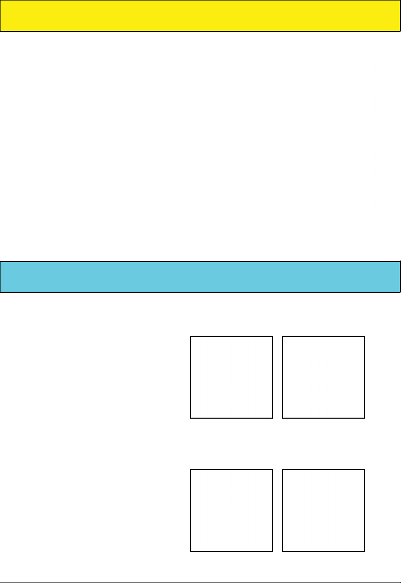
Models:
CDX2532G
CDX2532G-78
KEEP THIS BOOKLET
Please read and follow carefully before installing, operate, assemble, or maintain this product.
Make sure to observe all safety information to avoid injury of yourself and others. Non compli-
ance with recommended information can result in injury or property damage! Keep this booklet
for future reference.
Description
This plunger pump is capable of
pumping 2-2.5 GPM at 2500-3200 PSI.
Designed to be coupled with a direct drive
gasoline engine with a shaft spinning up
to 3400 RPMs. The three legged design
provides a convenient connection to
most 5hp 7/8” shaft engines. This
hollow shaft pump includes a
thermal relief valve(for protection
from overheating), an adjustable
unloader valve (for changing the
amount of psi for varying applications),
and a soap injection system (for those
really dirt jobs).
Page 3

Limited Warranty
Axial Radial Pumps are warranted for a period of two years to the
original purchaser. This is from the date shipped from factory or U.S.
Warehouse.
Warranty covers manufacturing defects or workmanship; that may
develop under normal use and service in a manner up to the directions
and usage recommended by the manufacturer.
Warranty does not apply to misuse or when pump or accessory is
altered or used in excess of recommended speeds, pressures, tempera-
tures or handling uids not suitable for pump or accessory material
construction. Warranty does not apply to normal wear (such as but not
limited to: seals/packings, valves, plungers and sealing o-rings), freight
damage, freezing damage or damage caused by parts or accessories
not supplied by Vortex Power Products.
Liability of manufacturer for warranty is limited to repair or replacement of parts only at the option of the manufacturer when such products are found to be of original defect or workmanship at the time it
was shipped from factory. This warranty is in lieu of all other warranties,
expressed or implied, including any warranty of merchantability and of
any and all other obligations or liabilities on the part of the manufacturers or equipment.
Page 4

6.12 6.61 7.07 7.25 7.42 7.59 7.75 7.91 8.06 8.22 8.37 8.52 8.66 9.01 9.35 9.68 10.00 10.61 11.18
PSI PSI PSI PSI PSI PSI PSI PSI PSI PSI PSI PSI PSI PSI PSI PSI PSI PSI PSI PSI PSI
1.00 1.12 1.22 1.32 1.41 1.45 1.48 1.52 1.55 1.58 1.61 1.64 1.67 1.70 1.73 1.80 1.87 1.94 2.00 2.12 2.24
1000 1250 1500 1750 2000 2100 2200 2300 2400 2500 2600 2700 2800 2900 3000 3250 3500 3750 4000 4500 5000
2.0
ORIFICE
NOZZLE
NOZZLE SELECTION CHART
1.25 1.40 1.53 1.65 1.77 1.81 1.85 1.90 1.94 1.98 2.02 2.06 2.09 2.13 2.17 2.25 2.34 2.42 2.50 2.65 2.80
2.5
1.50 1.68 1.84 1.98 2.12 2.17 2.22 2.27 2.32 2.37 2.42 2.47 2.51 2.56 2.60 2.70 2.81 2.90 3.00 3.18 3.35
3.0
1.75 1.96 2.14 2.32 2.47 2.54 2.60 2.66 2.71 2.77 2.82 2.88 2.93 2.98 3.03 3.15 3.27 3.39 3.50 3.71 3.91
3.5
2.00 2.24 2.45 2.65 2.83 2.90 2.97 3.04 3.10 3.16 3.22 3.29 3.35 3.41 3.46 3.61 3.74 3.87 4.00 4.24 4.47
4.0
2.25 2.52 2.76 2.98 3.18 3.26 3.34 3.42 3.49 3.56 3.63 3.70 3.76 3.83 3.90 4.06 4.21 4.36 4.50 4.77 5.03
4.5
2.50 2.80 3.06 3.31 3.54 3.63 3.71 3.79 3.87 3.95 4.03 4.11 4.18 4.24 4.33 4.51 4.68 4.84 5.00 5.30 5.59
5.0
2.75 3.07 3.37 3.64 3.89 3.99 4.08 4.17 4.26 4.35 4.43 4.52 4.60 4.68 4.76 4.96 5.14 5.33 5.50 5.83 6.15
5.5
3.00 3.35 3.67 3.97 4.24 4.35 4.45 4.55 4.65 4.74 4.84 4.93 5.02 5.11 5.20 5.41 5.61 5.81 6.00 6.36 6.71
6.0
3.25 3.63 3.98 4.30 4.60 4.71 4.82 4.93 5.03 5.14 5.24 5.34 5.44 5.54 5.63 5.86 6.08 6.29 6.50 6.89 7.27
6.5
3.50 3.91 4.29 4.63 4.95 5.07 5.19 5.31 5.42 5.53 5.64 5.75 5.86 5.96 6.06 6.31 6.55 6.78 7.00 7.42 7.83
7.0
3.75 4.19 4.59 4.96 5.30 5.43 5.56 5.69 5.81 5.93 6.05 6.16 6.27 6.39 6.50 6.76 7.02 7.26 7.50 7.95 8.39
7.5
4.00 4.47 4.90 5.29 5.66 5.80 5.93 6.07 6.20 6.32 6.45 6.57 6.69 6.81 6.93 7.21 7.48 7.75 8.00 8.49 8.94
8.0
4.25 4.75 5.21 5.62 6.01 6.16 6.30 6.44 6.58 6.72 6.85 6.98 7.11 7.24 7.36 7.66 7.95 8.23 8.50 9.02 9.50
8.5
4.50 5.03 5.51 5.95 6.36 6.52 6.67 6.82 6.97 7.12 7.26 7.70 7.53 7.66 7.79 8.11 8.42 8.71 9.00 9.55 10.06
9.0
4.75 5.31 5.82 6.28 6.72 6.89 7.05 7.22 7.36 7.51 7.66 7.81 7.95 8.09 8.23 8.56 8.89 9.20 9.50 10.08 10.62
9.5
5.00 5.59
10.0
5.50 6.15 6.74 7.28 7.78 7.97 8.16 8.34 8.52 8.70 8.87 9.04 9.20 9.37 9.53 9.92 10.29 10.65 11.00 11.67 12.30
11.0
6.00 6.71 7.35 7.94 8.49 8.70 8.90 9.10 9.30 9.49 9.67 9.86 10.04 10.22 10.39 10.82 11.22 11.62 12.00 12.73 13.42
12.0
6.25 6.99 7.65 8.27 8.84 9.06 9.27 9.48 9.68 9.88 10.08 10.27 10.46 10.65 10.83 11.27 11.69 12.10 12.50 13.26 13.98
12.5
6.50 7.27 7.96 8.60 9.19 9.42 9.64 9.86 10.07 10.28 10.48 10.68 10.88 11.07 11.26 11.72 12.16 12.59 13.00 13.79 14.53
13.0
7.50 8.39 9.19 9.92 10.61 10.87 11.12 11.37 11.62 11.86 12.09 12.32 12.55 12.77 12.99 13.52 14.03 14.52 15.00 15.91 16.77
15.0
10.00 11.18 12.25 13.23 14.14 14.49 14.83 15.17 15.49 15.81 16.12 16.43 16.73 17.03 17.32 18.03 18.71 19.36 20.00 21.21 22.36
20.0
GPM
Page 5
General Safety Information
This pump is designed for pumping
non-amable or non-combustible
uids. The pump is intended to
pump clean ltered water.
Modictaions to the manufacturer
design is not recommended.
Do not operate in an enclosed area
or around explosive materials. Always make sure you have adequate
ventillation in your work environment.
Always wear the proper safety
equipment when operating this
pump.
Do not allow children to operate
this pump.
Be careful with where you point the
high-pressure discharge. Never
point it at a person or animals body
or body part.
Do not exceed pumps specications in shaft speed or discharge
pressure.
Maximum temperature of pumped
water should not exceed 140°F.
Winter/Long Term Storage
1. Drain all of the water from the
pump.
2. Screw in bottle of Vortex Pump
Saver to the garden hose inlet and
open up the valve on the cap of the
bottle.
3. Make sure your pressure washer
on off switch is in the off position and
slowly pull on the pull start rope while
squeezing the pump saver bottle to
cycle the contents through the pump.
4. When you see pump saver come
out of the outlet you can stop cycling
the pump. Close the valve on the
bottle cap and remove it from your
pump.
5. Before your next use make sure
you ush the pump by running fresh
water through it.
Page 6

1. Make sure the unit is powered off. Remove the mounting bolts that hold the old
pump to the engine, and remove the old pump. Make certain that the engine shaft is
clean and free of debris before installation of the new pump.
2. Place the shaft key into the key slot on the engine shaft. Hold it in place with your
nger while sliding the pump onto the engine shaft. Make sure that the shaft key
does not slide up the shaft and stays rmly in the key slot or you can risk damaging
the pump hollow shaft when tightening the mounting bolts.
3. After placing the pump onto the shaft with the key in place line up the 4 mounting
bolt holes with the 4 engine mount bolt holes. Slide your pump onto the shaft until
the mounting tabs are ush with the frame. There should be no gap between the
mounting tabs and engine.
Page 7

Installation
4. Once the pump is ush with the frame it’s time to bolt it together. Insert the
mounting bolt with a washer through the mounting tab bolt hole and tighten down
the bolts when you are absolutely positive that the mounting tabs are ush with the
engine or you can break a tab or damage the hollow shaft inside the pump.
5. Once the pump has been mounted to the engine make sure the on off switch is in
the off position and then slowly pull the pull start rope to ensure that the engine shaft
spins freely inside the pump. If it does not spin freely then the shaft key either slid up
the shaft and is binding or the pump isn’t ush to the engine and is binding because
it is tilted at an angle. Remove the pump and reinstall ensuring that each step is done
correctly.
Page 8

Unloader Adjustment
1. The rst step is to reset the
unloader. Turn the adjustment
knob counter clockwise until
there is absolutely no pressure
against the spring inside the
unloader.
2. Connect hoses to your pump
and run water to it. Now you will
need to purge the air from your
hoses by pulling the trigger until
only water comes out.
3. Run your pressure washer
4. With your pressure washer
running hold down the trigger
and slowly turn the adjustment
knob clockwise.
5. When pressure no longer
increases turn the knob counter
clockwise 1/2 turn and release
the trigger. NOTE: If the engine
stalls or acts as if it is still underload then you will need to repeat
steps 4 and 5 again until your
pressure washer goes into bypass mode and there is no load
on the engine.
6. Below the adjustment knob
you will nd a brass stopper
with a set screw. Loosen the set
screw and adjust the stopper
until it is snug against the adjustment knob. Tighten the set
screw to keep it in place
Page 9

Troubleshooting
Symptom Possible Cause Corrective Action
Oil leak between crankcase
and pump section
Frequent or premature
failure of the packing
Pump runs but produces
no ow
Pump fails to prime Air is trapped inside pump Disconnect discharge hose from pump. Flood
Pump loses prime, chattering noise, and/or pressure
uctuates
Low pressure at nozzle 1. Unloader valve is
Pressure gauge uctuates 1. Valves worn or blocked by
Low pressure 1. Worn nozzle 1. Replace with new nozzle of proper size
Pump runs extremely rough,
pressure very low
Worn oil seals around plunger Replace crankcase plunger oil seals
1. Cracked, damaged, or worn
plunger
2. Overpressure to inlet
manifold
3. Material in the uid being
pumped
4. Excessive pressure and/or
temperature of uid being
pumped
5. Running pump dry 5. Do not run pump without water
Pump is not primed Flood suction then restart the engine
1. Air leak in suction hose or
inlet
2. Clogged suction strainer 2. Clean strainer
by-passing
2. Incorrect or worn nozzle 2. Make sure nozzle is matched to the ow
3. Worn packing or valves 3. Replace packing or valves
debris
2. Packing worn 2. Replace packing
2. Air leak in inlet connection 2. Disassemble, reseal, and reassemble
3. Relief valve stuck, partialy
plugged or improperly adjusted valve seat, valve seat worn
4. Worn packing. Abrasive in
pump cavitation. Inadequate
water.
5. Worn inlet, discharge valve
blocked or dirty
1. Inlet restrictions and or air
leak
2. Stuck inlet or discharge
valve
1. Replace plunger
2. Reduce inlet pressure
3. Install lter to pump inlet
4. Check pressure and water inlet tempera-
ture. Be sure they are within specied ranges
suction hose and run the pump until all air
has been evacuated
1. Remove suction line and inspect it for
a loose liner or debris lodged in the hose.
Avoid all unnecessary bends and do not kink
1. Make sure unloader is adjusted properly
and by-pass seat is not leaking
and pressure of the pump. If the nozzle is
worn the replace it with a new one.
1. Clean or replace valves
3. Clean and adjust relief valve and check for
worn or dirty vavle seats
4. Install proper lter at manifold water inlet
5. Replace inlert and discharge valve
1. Clean out foreign material
2. Replace worn valve
Page 10

Troubleshooting
Symptom Possible Cause Corrective Action
Water leakage from under
manifold
Slight leak, oil leaking in the
area of the crankshaft
Water in crankcase 1. Humd air condensing into
Loud knocking noise in
pump
Worn packing or cracked
plunger
1. Worn crankshaft seal or
improperly installed oil seal
2. Bad Bearing 2. Install new bearing
water inside the crankcase
2. Worn packing and/or
cracked plunger
1. Cavitation or sucking air 1. Check that water supply is turned on
2.Broken or worn bearing 2. Replace bearing
Install new packing or plunger
1.Remove oil seal retainer and install new oil
seal
1. Change oil
2. Replace packing and/or plunger
Pump Servicing
Discharge Valve Removal
1. Remove the valve cap and inspect the
o-ring for damage and replace if neccessary.
2. Use a pair of needle nose pliers to remove
the check valve.
3. Use a small probe to move the poppet
up and down inside the valve to insure it is
function properly.
4. Remove any debris lodged between the
spring and poppet or the poppet and seat.
5. Inspect the seat o-ring for damage and
replace if damage is discovered.
Discharge Valve Installation
1. Insert the valve assembly squarely into the
valve port and rmly push it in using your
nger.
Should be quite snug when seated all of the
way.
2. Install the valve cap and torque it to down
221 ft. lbs.
Page 11

Pump Servicing
Inlet Valve Removal
1. Remove the pump head from the body.
Note:
Be careful not to damage parts below so they
can be reused if not worn
2. Remove the rst seal by inserting a screw driver
(or other device for levering) under the lip of the
seal and lift it up.
3. Using a pair of reversible pliers, carfully remove
the seal retainer from the head.
4. Carefully remove the check valve with a pair of
needle nose pliers.
5. Use a small probe to move the poppet up
and down inside the valve to insure it is function
properly.
6. Remove any debris lodged between the spring
and poppet or the poppet and seat.
7. Inspect the seat o-ring for damage and replace
if damage is discovered.
Inlet Valve Installation
1. Insert the valve assembly squarely into the
valve port and rmly push it in using your nger.
Should be quite snug when seated all of the way.
2. Insert the rst water seal (it wil be the thicker
one) and with your nger press it into the valve
port with the at side facing up. Should be a tight
t.
3. Assemble the retainer with the remaining water
seal inplace (at side facing up). Lubricate the retainer o-ring then insert the assembled retainer all
of the way into the valve port. The retainer should
stick out past the head surface.
4.Reinstall head and torque bolts to 221 ft. lbs.
Page 12

Pump Servicing
Easy Start Removal
1. Remove the easy start plug and inspect the
o-ring for damage or wear and replace if necessary.
2. Remove the ball and spring then clean them
and the barb of calcium build-up.
3. Using a coarse wood screw, insert it into the
seat and twist it until the threads catch in the
small hole at the bottom of the seat. When the
treads catch you will be able to pull the seat
out. Inspect the o-ring for damage or wear and
replace if necessary.
Easy Start Installation
1. Insert the seat then use something long and
skinny to push it fully into position inside the
pump head.
2. Place the spring in next making sure that it is
inserted inside the seat.
3. Insert the ball on top of the spring.
4. Install the easy start plug and torque it down
to 221 ft. lbs.
Unloader Valve Removal
1. Remove unloader from the head.
2. Using a hooked pick pull pull out the seat.
It may be stuck tight so you may need to pull
from multiple angles to work it out. Inspect
seat o-ring for damage or wear and replace if
necessary.
Page 13

Pump Servicing
Unloader Valve Installation
1. Insert the seat squarely in the port with the
at side facing up and the concave side facing
down.
2. Press the seat into place with a wide blunt
tool that will allow you to distribute pressure
equally across the seat while pressing it in
place.
3. Reinstall the unloader valve and tighten.
Chemical Injector Removal
1. Remove the hose barb and inspect the o-ring
for damage or wear and replace if necessary.
2. Remove the ball and spring. Then clean them
and the barb of calcium build-up.
Chemical Injector Installation
1. Insert ball into the injector barb followed by
the spring
2. Place the pump so that you can place the
assembled hose barb into the injector port
without the components falling out.
3. Tighten down the injector barb until snug.
Do not overtighten because the barb can easily
break or strip out the threads.
Page 14

Pump Breakdown
H 1002.0409 Easy Start Kit
G 1002.0458 Single Valve Cap
I 1001.3302 Vent Tube
D 1001.3298 Water Seal Kit
C 1001.3300 Check Valve Kit
E 1000.6353 Garden Hose Fitting
F 1001.2150 Thermal Valve
A 1002.0405 Unloader Valve
B 1001.3301 Injector Kit
PART NO. Description Price
Replacement Part Kits
Page 15

Notes
Page 16

 Loading...