

Page 1
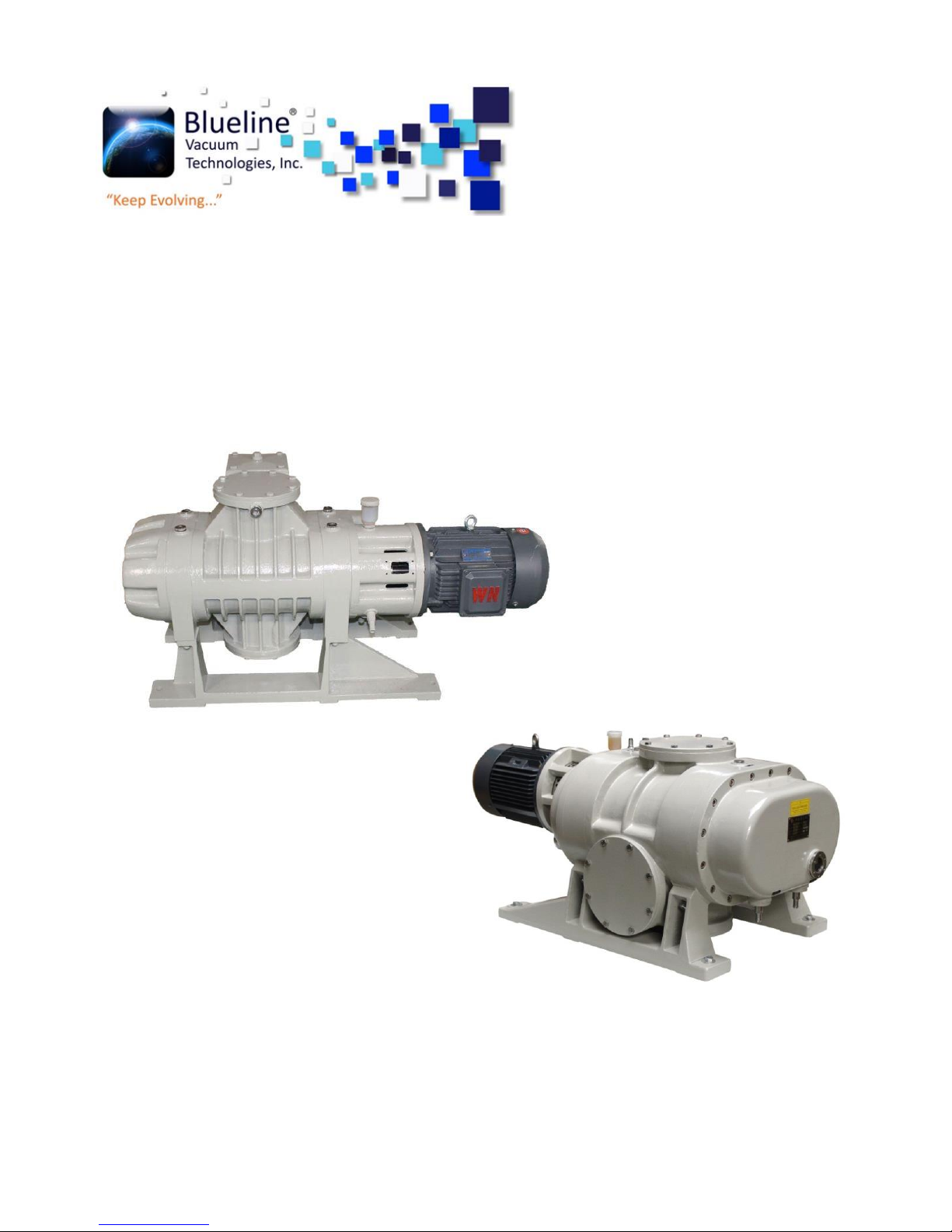
With By pass
Without by pass
www.bluelinevacuum.com
OPERATING INSTRUCTIONS
VORTEX ROOTS VACUUM PUMPS
Page 2

INDEX
1. Important basic information ..........................................................................................................4
1.1 Statement .................................................................................................................................4
1.2 Warranty ..................................................................................................................................4
2. Survey.............................................................................................................................................5
2.1 Introduction .............................................................................................................................5
2.2 Features....................................................................................................................................5
2.3 Usage and model explanation: .................................................................................................6
3. Performance specification ..............................................................................................................7
3. 1250-2160 m3/hr pump Technical data ......................................................................................7
3.2 Vortex series pump performance curve ...................................................................................7
3.3 5000-9000 m3/hr pump Technical data ....................................................................................8
3.4 Vortex B Series pump performance curve ................................................................................8
4. Operating principle.........................................................................................................................9
5. Installation ...................................................................................................................................10
6. Operating instructions ..................................................................................................................11
6.1 Preparations before starting ..................................................................................................11
6.2 Starting ...................................................................................................................................11
6.3. Stopping ................................................................................................................................11
7. Maintenance & accessories ..........................................................................................................12
7.1 Safety information ..................................................................................................................12
7.2 Oil change/gear box ...............................................................................................................12
7.3 Oil Change/Shaft Seal Housing ...............................................................................................13
7.4 Cleaning the Fan and the Cooling Fins ....................................................................................13
7.5 Cleaning the Pumping Chamber .............................................................................................13
7.6 Disassembling and assembling procedure ..............................................................................13
7.6.1 Disassembling procedure: ...................................................................................................13
7.6.2 Assembling procedure: ........................................................................................................14
7.7 Accessories .............................................................................................................................14
7.8 Troubleshooting .....................................................................................................................15
8. Pump structure ............................................................................................................................17
8.1 Vortex 5000 pump structure ..................................................................................................17
8.2 Vortex B series pump structure ..............................................................................................19
Page 3

9. Installation drawing ......................................................................................................................21
9.1 Vortex series installation size (Unit: mm) ...............................................................................21
9.2 Vortex B series installation size (Unit: mm) ............................................................................22
9.3 Vortex B series Exploded View ...............................................................................................23
10. Contact .......................................................................................................................................24
Page 4

1. Important basic information
1.1 Statement
These operating instructions form part of the technical documentation of the system, and are
addressed to the person in charge of the plant, who is obliged to provide them to the staff
responsible for the system set-up, connection, operation and maintenance.
He must ensure that all information included in the operating instructions and the enclosed
documents have been read and understood.
These operating instructions are the exclusive copyright of
Blueline Vacuum Technologies, Inc.
Phone +52 7222167069
Phone +52 7227059601
Metepec, Mexico, 52175
Any company or personal cannot duplicate, transfer it to third party, or make illegal business use.
Any operation on the pump should be in accordance with the instruction.
1.2 Warranty
The manufacture does not accept liability for damage to persons, animals, objects or incomplete
observance of the safety precautions included in these operating instructions or by modifications
to the system or use of improper spare parts.
Warning: Do not move and modify any safety and insulating device, which may cause great
danger.
Warning: The pump can only pump gas. However, it cannot pump any gas that is poisonous,
inflammable, explosive and corrosive, either gas that reacts with vacuum gas. The pump cannot
used to transit gas. It could be used to pump gas with few particles, however, it cannot pump
Chemicals, condensates, powders and other granules which will damage equipment, reduce
performance and shorten service life.
Warning: Do not put the pump in rain, steam and humid air which may cause an electric shock, a
short circuit and the damage of the whole system. Warning: Whenever changing the wire, please
use qualified wire.
Warning: Use suitable fuses to prevent short circuit.
Warning: Do not put hands or other stuff into the pump when it operates. The behavior will cause
bodily injury and damage of pump parts.
Attention: Make sure the pipe of the cooling water is not blocked, otherwise the temperature of
pump will be too high.
4
www.bluelinevacuum.com
Page 5

Diagram 1
Attention: The pump needs regular maintenance; otherwise there will be damage, or even
reduction of its life. Cut down circuit before check and repair, and only operate when power is off.
Attention: The temperature of operation environment should be 5°C- 40°C to prevent the pump
from damaging and shortening the life of use.
Attention: The pump should be put at safe places with proper ventilation, solid and flat base, and
clean floor, without corrosive gas. Otherwise, the pump will be damaged and the life of use will be
shortened.
Attention: In cold area, the coolant jacket must be drained after car stopped. Otherwise the
coolant may freeze and thus damage the pump shell.
2. Survey
2.1 Introduction
Roots pump have Vortex series and Vortex B series. As the input pressure is between 6.5-65 Pa,
the pumping speed is no less than 250m3/h, 500m3/h, 1000m3/h, 2000m3/h, 5000m3/h,
6000m3/h and 9000m3/h. It is a kind of roots vacuum pump in which a couple of lobed rotors turn
like 8- shape in high speed synchronously. Two rotors rotate
and produce aspiration and exhaust which principle is just like a
roots blower. As it works in a lower pressure, the free flow
distance of gas molecule is longer and the resistance of gas
passing a small gap is much large. Thus, a bigger compression
ratio can be gained so that it can also be used as a blower
pump. But it cannot discharge the gas to atmosphere directly
and requires to be used with a vacuum pump in series
connection.
Then the sucked gas is discharged to atmosphere through the
vacuum pump (as Diagram 1).
2.2 Features
(1) There are definite gaps between rotor and pump’s cavity, rotor and rotor which are not in
contact. As a result:
a. No friction, lower power consumption that is compared with an oil sealed mechanical vacuum
pump of the same pumping speed.
b. No Oil-sealing and lubrication so as to avoid being polluted to the vacuum pump by oil steam.
c. It is ok for pumping the gas with a little dust.
5
www.bluelinevacuum.com
Page 6
(2) As the rotor has a good geometric Symmetry, its rotational speed is higher than a common oilsealing mechanical vacuum pump and at the same pumping speed it has features of smaller
volume and lighter weight.
(3) When the pump is in operation, there is less vibration and its volume operating ratio is
about kv≈ 0.5.
(4) There is no compression in the pump similar than that produced in a mechanical vacuum
pump. So no discharge valve is required but agglutinative steam can be removed.
(5) The pump can be started quickly and a limit vacuum can be reached in a short time.
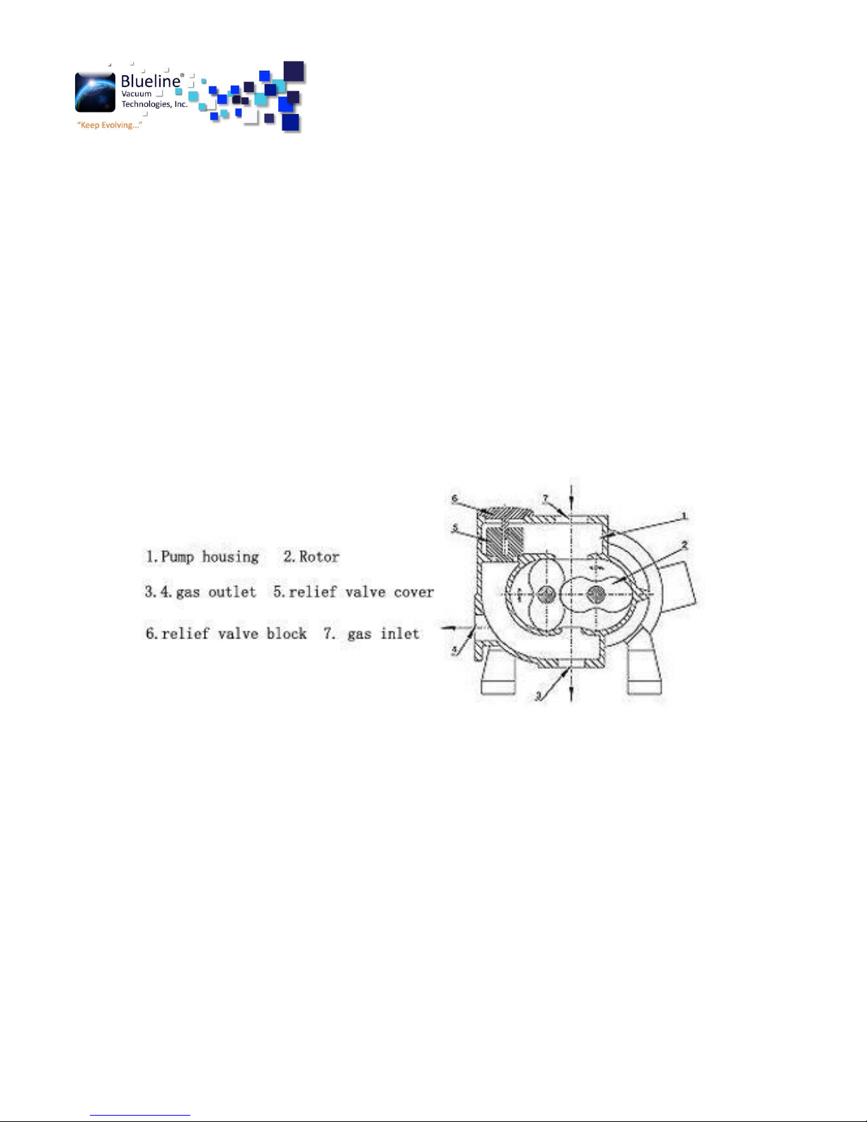
Except the above features, Vortex B series Roots Pump has it’s own relief valve which functions
to control roots pump's differential pressure between air-inlet and air-outlet. When the
differential pressure is over standard one the relief valve opens automatically. Because the
pump's inlet-outlet is interlinked, some of gas returns to the inlet. At this time, the pump operates
in a constant differential pressure. When the differential pressure is lower than that of a relief
valve, the valve close automatically (shown as Diagram2)
2.3 Usage and model explanation:
Usage: vacuum degassing, vacuum smelting, vacuum heat treating etc, in metallurgical industry
and can also be used in chemical industry. Foodstuff, medicine, Electrical manufacture etc.
Especially when a water-ring vacuum pump is used for its pump, it can extract the gas with large
steam. So it is much suitable for productive procedures of distillation, evaporation, freezing and
drying etc.
Model explanation: Vortex/Vortex B-5000
Vortex--roots vacuum pump; Vortex B with relief valve 5000--pumping speed 5000m3/h
Diagram 2
6
www.bluelinevacuum.com
Page 7

3. Performance specification
3. 1250-2160 m3/hr pump Technical data
3.2 Vortex series pump performance curve
www.bluelinevacuum.com
7
Page 8
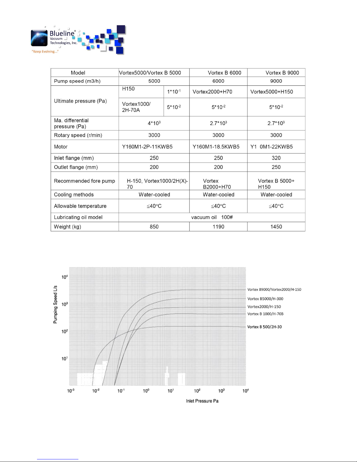
3.3 5000-9000 m3/hr pump Technical data
3.4 Vortex B Series pump performance curve
8
www.bluelinevacuum.com
Page 9

4. Operating principle
The pump’s operating principle is shown as Diagram 3.When the pump is rotating, the gas in an
exhausted container directly enters the space encircled by two rotor and pump cavity and the gas
entered before is merely encircled by space Vo(see the shaded parts in Diagram). The mixed gas in
Vo is merely encircled, but not be compressed and expanded. With the rotation of a rotor, the
rotor’s top reaches the outlet port edge, the gas in pump’s outlet port will spread to the space Vo,
the mixed gas in Vo will be carried to a pump to be exhausted. Thus, with the rotor’s continuous
operation, more gas will be carried to outlet port and exhausted by the pump. That is the
functional principle of the pump’s volume.
When this pump is operating under a very low pressure, because of rotor’s high speed (3000rpm),
the linear speed of the rotor’ surface is near to molecular heat pace. At this time, the gas impacted
on the rotor is brought to an outlet port with a higher pressure and removed by beforehand
vacuum pump. That is the molecular functional principle of thin pump.
The combined action by the two principles makes this pump have features of a big pumping rate
and a stable pumping rate curve in an interval of 1.3x10³~1.3 Pa.
According to this pump’s characteristics and different operating condition, different fore pump can
be freely chosen which is not required too high vacuum, but required to remove corrosive gas with
large steam or little dust. Completed with a double-stage water-ring vacuum pump and a piston
vacuum pump, the limit vacuum is lower and its power proportioning is different, too. Our
company can specially design various pump’s unit according to user’s different requirements and
operating conditions .Welcome to contact us by call or email.
Diagram 3
9
www.bluelinevacuum.com
Page 10

5. Installation
1. Before installation, checking each parts and make sure there have no damaged, and to see
whether the product is fit to order contract.
2. The pump must be installed in a place of cleaning, no dust or a little dust and infection with
dielectrics. According to its operating condition, the pump’s inlet port can be equipped an anti-
dust device (such as an oil-sealed mechanical pump used as pump).
3. The pump’s operating environment temp. is 5-40 ℃ and the max. Temperature rise is cannot
exceed 100 ℃.
4. According to operating condition, the pump can be installed to a cement base or steel frame
base which should be calibrated. Otherwise, it will be seriously affect the pump’s normal
operation.
5. The gas inlet pipe should be kept sealing, even a small leakage will affect its vacuum.
6. The length of a pipe is as short as possible, using less joint and elbow with its diameter less than
its pump’s bore.
7. A flexible soft pipe such as a metal bellows should be linked between this pump and a fore
pump so as to prevent damaging this pump because of fore pump’s vibration.
8. It is better to equipped a vacuum valve on the pump’s inlet and outlet pipes so as to keep the
vacuum of pump cavity after stopping operation.
9. A valve should be installed on inlet pipe for cooling water so as to regulate water quantity and
control the outlet temperature of cooled water at 20-40℃。 Pay attention to the water
temperature not over 40℃ so as to avoid producing sediment in a water tank.
10. An advance vacuum pump must be used as this pump’s fore pump which is not used alone. If
an oil-sealed mechanical vacuum pump is used as its pump, the two may be used in series
connection. So this pump is not suitable for drawing out the gases such as too much oxygen
content, explosiveness, corrosion to ferrous metal, chemical reaction to vacuum oil and containing
dust etc. Otherwise, the service life of a fore pump will be shortening.
10
www.bluelinevacuum.com
Page 11

6. Operating instructions
6.1 Preparations before starting
① Check the cooling water pipe is open.
② Check there have enough lubrication oil in end cover A and end covers B, make sure the oil
should be reached to the oil level of oil mirror. The oil cup of oil sealing should be filled full usually
and keep clean. New pump’s oil must be changed after operating30 ~ 50 hours. After then, the
oil can be changed according to the operating condition.
③ if there have dust and other metal powder in the exhausted gas, anti-dust or filler devices
should be installed in front of air inlet port. If there have corrosive gas in exhausted gases, some
neutralizing measures should be adopted.
④ Check there have no any loosening in various parts .Motor’s rotational direction should be
in accordance with arrow direction on a pump.
6.2 Starting
① Start the pump
② Open the gas inlet valve of this pump
③ Open the water cooling valve and start this pump.
④ The pump should be in a stable operation and the rotor without crash. Or should be stopped.
⑤ There is no leakage in the oil –sealed position of a pump’s shaft.
⑥During the operating, if the temperature rise is too high ,the reading of current meter is
suddenly changed, an abnormal noise or other unusual phenomena appears ,the pump should be
stopped immediately.
6.3. Stopping
① Close gas inlet valve which on inlet port at first.
② Stop pump (and close the inlet valve )
③ Stop the fore pump
④ Close the water inlet valve of water cooling pipe.
⑤ If the pump’s operation is stopped for a long time or its operating in a cold zone, the cooling
water must be drained out completely.
Otherwise, the cooling water will be frozen and make the pump’s castings in frost crack.
11
www.bluelinevacuum.com
Page 12

7. Maintenance & accessories
7.1 Safety information
The safety information was given in the following applies to all maintenance work.
Warning: Disconnect the electrical power before disassembling the pump and venting to
atmospheric pressure. Make absolutely sure that the pump cannot be accidentally started. If the
pump has been pumping harmful substances, determine the nature of hazard and introduce
suitable safety measure.
When drying or blowing out the pump with compressed air, technician must observe and obey all
safety regulations.
Caution: All maintenance and cleaning work described in this section must be only carried out by
the trained person.
When handling the used oil plus observe the relevant environment regulations.
Improper maintenance or repairs may affect the service life and pump performance.
7.2 Oil change/gear box
Warning: Before pumping oxygen or other highly reactive gases at concentrations which
exceeding 20% in the atmosphere will be necessary to choose a special pump. Such a pump have
to modified and degreased as well as a special lubricant oil. Bearings consume a little oil and the
gear under clean operating conditions. We recommend you to change the oil after the first 500hrs
operation to remove any wearing residue. Then, under the normal operating conditions, change
pump oil after every 3000hrs operating. Change oil much more frequently when pumping
corrosive vapors or large amount of dust or when happing from the atmospheric pressure to
working pressure usually.
Warning: Before removing the oil-drain/oil filling screw, the pump should be stooped at first and
vent to atmosphere pressure (have no vacuum inside pump chamber).
When the pump has become warm during operation, the casing and the oil temperature may
exceed 80 ℃, then should leave the pump to cooling down.
Always wear protective gloves to protect yourself against aggressive residues in the oil .
Loosen the oil-drain/oil-fill screw and then drain out the oil. Clean the sealing surface and firmly
reinstall the oil-drain screw using a gasket which is in a perfect condition. Wipe off any oil residues
from the casing. Fill in new oil. Make sure to use the right kind of oil.
Caution: We recommend the vacuum oil is N100 or N62. Make sure the oil level is correct .If the
oil level is too low, the bearings and gearwheels will not lubricated adequately; if it is too high, oil
may enter into the pump chamber. Clean the oil-fill port and reinstall the screw using a gasket
which is in a perfect condition.
12
www.bluelinevacuum.com
Page 13

Caution: The oil fill port must be sealed tightly. Or the air will be entered into pump chamber
through impeller seals.
7.3 Oil Change/Shaft Seal Housing
Warning: The oil in the shaft seal housing should be changed every 3,000hrs operating. Loosen the
oil-drain screw under the shaft seal housing, drain out the oil and then screw the oil-drain with a
gasket which is in a perfect condition. Fill in fresh oil through the oiler and the oil should be
reached to the oil level. .
Maximum level:
When the pump is warm = 1/2 of the height of the oiler.
When the pump is cold = 1/3 of the height of the oiler. Wipe off any oil residues from the
casing.
7.4 Cleaning the Fan and the Cooling Fins
Warning: The fans slits as well as the motor fins will be polluted when working in humidity
conditions. In order to ensure a sufficient air enter into motor and the pump’s casing, the fan grids
must be cleaned using a cleaning brush when polluted. Any coarse dirt must be removed from the
motor fins and the pump.
7.5 Cleaning the Pumping Chamber
Warning: Under dirty operating conditions, pump chamber and rotor will be getting polluted.
After removing the two connecting lines, the contaminants can be blown out with dry compressed
air or flushed out using a suitable solvent. Contaminants that cannot be removing completely from
the pump chamber with a wire brush, metallic sponge or scraper. Then change the oil.
Warning: During cleaning, the rotors must be turned only by hand. The loosened parts must not
remain in the pump. After cleaning, check the pump by slowly turning the rotor. The rotor should
be moved freely and without any resistance.
7.6 Disassembling and assembling procedure
7.6.1 Disassembling procedure:
7.6.1.1 Loosen screw and take down End cover B
7.6.1.2 Loosen screw (Vortex/Vortex B250-Vortex B 2000) or using hydraulic gear device (for
Vortex/Vortex B5000-9000) to take down gear.
7.6.1.3 Loosen screw and take down the gear cover, bearing, bearing seat B, piston ring and
piston ring cover.
7.6.1.4 Loosen screw and take down locating pin, and then disassembling side cover B.
7.6.1.5 Loosen screw and take down the motor, disassembling coupling.
7.6.1.6 Disassembling the locknut in the active/driven shaft.
13
www.bluelinevacuum.com
Page 14

Model
Vortex B 250
Vortex B
500
Vortex B
1000
Vortex B
2000
Vortex B
5000
Vortex B
6000
Vortex B
9000
Oil seal
SG32*47*8
SG30*55*10
SG60 *80 * 12
Qty (PCS)
2 2 2 2 2 2 2
7.6.1.7 Take down the shaft, rotor from the side cover B direction.
7.6.1.8 Disassembling the check ring, bearing cover, bearing seat A, side cover A, piston ring and
piston ring cover.
7.6.2 Assembling procedure:
Checking all the disassembled spare parts carefully, change spare parts if damaged . Clean parts
using petrol, diethyl ether or CCI4. Assembling all parts after dried. The pump body and side cover
should be sealing in plane. Assembling procedure is an opposite of disassembling procedure.
Technician should adjust the end cover clearance.
NOTE: Assembling the active/driven gear of Vortex 5000/9000 should be using hydraulic gear
device, using fastener to make sure the gear end cover come to the bearing end cover at first, and
then depressurization the oil pump
7.7 Accessories
14
www.bluelinevacuum.com
Page 15

Fault
Possible cause
Remedy
Pump does
not start.
Motor is connected incorrectly.
Connect the motor correctly.
Faulty pressure switch.
Replace the pressure switch.
Oil is too thick.
Change the oil or warm the oil and the
pump.
Motor rotor is malfunctioning.
After sales service.
Pump has seized up: damaged impellers,
bearings or gearwheels.
After sales service.
Pump gets too
hot.
Ambient temperature is too high or cooling
water supply is obstructed.
Install the pump at a suitable site or
ensure enough cooling water.
Pump is working in the wrong pressure
range.
Check pressure values of vacuum
system.
Pressure differential is too great.
Check pressure values of vacuum
system.
Gas temperature is too high.
Check the vacuum system.
Clearance between casing and impellers is
too small due to:
-
contamination
-
Distortion of pump.
Clean the pumping chamber.
Ensure that the feet and connecting
lines aren’t placing a strain on the pump.
Excessive frictional resistance due to
contaminated bearings and/or oil.
Exchange oil.
Oil level is too high.
Drain some oil to reach the correct level.
Oil level is too low.
Add oil to reach the correct level.
Wrong oil has been used.
Drain oil and fill in correct lubricant.
Bearing are malfunctioning.
After sales service.
Overflow valve does not open.
Clean or repair the valve.
Power
consumption
of the motor
is too high.
See fault “pump gets too hot”.
See fault “pump gets too hot”.
Wrong mains voltage supply for the motor.
Connect the motor to the correct
voltage supply.
Motor is malfunctioning.
Repair the motor or exchange it.
Oil is too thick.
Exchange the oil or warm up the oil and
the pump.
7.8 Troubleshooting
15
www.bluelinevacuum.com
Page 16

Fault
Possible cause
Remedy
Pump is too
loud.
Clearance between casing and impellers
is too small due to:
-contamination
-distortion of pump.
Clean the pumping chamber.
Ensure that the feet and connecting lines
aren’t placing a strain on the pump.
Bearing or gearing is damaged.
After sales service. Switch off the pump at
once.
Impellers strike the casing.
After sales service. Switch off the pump at
once.
Rotor runs out of true.
After sales service. Switch off the pump at
once.
Pump loses
oil.
Oil leak is visible:
Oil drain plug is not tight.
Drain lubricant, firmly screw in the oil drain
plug with a new gasket, and fill in the
correct quantity.
No oil leak is visible;
See fault “oil in the pumping chamber”
See fault “oil in the pumping chamber”
Oil level in the
oiler drops
Oil leak is visible:
Outer shaft seal is malfunctioning.
Exchange shaft seals.
No oil leak is visible;
Inner shaft seal is malfunctioning.
Exchange shaft seals.
Oil turns dark.
Oil has broken down.
Change the oil.
Pump gets too hot.
See fault “pump gets too hot”. After solving
the problem change the oil.
Oil in the
pumping
chamber
.
Oil level is too high.
Drain lubricant to reach the correct oil level.
Oil leaks out of the system.
Check system.
Pump is not installed on a flat horizontal
surface.
Install pump correctly.
Pump has an external leak.
Check proper fit of oil-fill and oil-drain
plugs, replace gaskets if necessary.
Pump has an internal leak.
After sales service.
Impeller rings are malfunctioning.
After sales service.
Pumping
speed of
the pump is
too low
Motor is connected incorrectly.
Connect the motor correctly.
Motor fault.
After sales service.
Pump or pump system has a leak.
Find and seal the leak.
Overflow valve does not close.
Clean or repair the valve.
Flow resistance in the intake or discharge
line is too high.
Use intake and discharge lines of sufficient
diameter.
16
www.bluelinevacuum.com
Page 17

8. Pump structure
8.1 Vortex 5000 pump structure
17
www.bluelinevacuum.com
Page 18

Sr.
Name
Qty
Material
Sr.
Name
Qty
Material
1 end cover A
1 HT200
14
side cover
2 HT250
2
connecting base
for motor
1 HT200
15
end cover B
1 HT250
3 sealing seat
1 HT250
16
active gear
1
20CrMnTi
4 sealing cover
1 HT200
17
drive gear
1
20CrMnTi
5 shaft sleeve A
1
20CrMnTi
18
bearing seat
A
2 HT200
6 shaft sleeve B
1 45#
19
bearing seat
B
2 HT200
7 gland cover
1 Q235-A.F
20
bearing cover
A
2 HT200
8
repair spare part
gasket
1 HT200
21
bearing cover
B
2 HT200
9 active rotor shaft
1
22
oil deflector
4 HT150
10
pump body
1 HT250
23
sealing ring
set
4 QT400
11
left frame
1 HT250
24
side cover
bushing
4 HT200
12
right frame
1 HT250
25
bearing C
1 HT150
13
drive rotor shaft
1
26
bearing D
3 HT150
18
www.bluelinevacuum.com
Page 19

8.2 Vortex B series pump structure
19
www.bluelinevacuum.com
Page 20

Sr.
Name
Material
Sr.
Name
Material
1 Pump body
HT250
19
Bearing gland cover
B
HT200
2 Side cover
HT200
20
Shaft sleeve D
20CrMnTi
3 End cover A
HT200
21
Shaft sleeve C
20CrMnTi
4 End cover B
HT200
22
Spring
65M
n
5
Frame A
HT250
23
Oil flinger
2/Q235-A.F
6
Frame B
HT250
24
balance plate
7 Active shaft
HT250
25
Silencing plate
8 Drive shaft
HT250
26
Junk ring
Chromium
alloy cast iron
9
Rotor
27
Damping block
10
Active gear
20CrMnTi
28
bolt
35#
11
Drive gear
20CrMnTi
29
spring
65 M
n
12
Connecting seat for
motor
HT200
30
Inlet cover
Q235-A.F
13
Shaft sleeve A
20CrMnTi
31
Screw nut
14
Shaft sleeve
45#
32
Reinforced oil sealing
NBR
15
Oil deflector
HT1500
33
coupling
16
Bearing seat A
HT200
34
Water pipe connector
2Cr13
17
Bearing seat B
HT200
35
Relief valve cover
18
Bearing gland cover A
HT200
36
motor
20
www.bluelinevacuum.com
Page 21

Model A
A1
A2
A3
A4
A5 B
B1
B2 H
H1
H2
H3
H4 K
Vortex
250
752
560
223
178
343 -
294
240
184
288
28
118
38
175 14
Vortex
500
900
640
252
195
385 -
400
320
260
365
28
145
40
225 20
Vortex
1000
1074
800
332
275
465 -
400
320
260
403
30
158
53
243 20
Vortex
2000
1355
830
393
278
483
557
574
480
354
560
39
205
40
345 24
Vortex
9000
1690
1000
500
316
632
670
630
520
410
590
37
220
35
355 24
Model
D
D1
D2 E d
d1
d2 F N
N1
N2 W Q M
Vortex
250
80
125
145
4-M8
80
125
145
4-M8
80
125
145
145
4-M8 -
Vortex
500
100
145
170
4-M10
100
145
170
4-M10
100
145
170
183
4-M10 -
Vortex
1000
150
195
220
8-M10
150
195
220
8-M10
100
145
170
183
8-M10 -
Vortex
2000
200
250
275
8-M10
200
250
275
8-M10
200
250
275
275
8-M10
M20
Vortex
9000
250
310
335
12-M10
200
260
265
12-M10
200
260
285
275
12-M10
M20
9. Installation drawing
9.1 Vortex series installation size (Unit: mm)
21
www.bluelinevacuum.com
Page 22

Model
A
A1
A2
A3
A4
A5 B B1
B2 H H1
H2
H3
H4 K
Vortex
250
752
560
223
178
343 - 294
240
184
288
28
118
38
175
14
Vortex
500
900
640
252
195
385 - 400
320
260
365
28
145
40
225
20
Vortex
1000
1074
800
332
275
465 - 400
320
260
403
30
158
53
243
20
Vortex
2000
1355
830
393
278
483
557
574
480
354
560
39
205
40
345
24
Vortex
9000
1690
1000
500
316
632
670
630
520
410
590
37
220
35
355
24
Model
D
D1
D2 E d
d1
d2 F N
N1
N2 W Q
M
Vortex
250
80
125
145
4-M8
80
125
145
4-M8
80
125
145
192
4-M8
-
Vortex
500
100
145
170
4-M10
100
145
170
4-M10
100
145
170
245
4-M10
-
Vortex
1000
150
195
220
8-M10
150
195
220
8-M10
100
145
170
285
8-M10
-
Vortex
2000
200
250
275
8-M10
200
250
275
8-M10
200
250
275
375
8-M10
M20
Vortex
9000
250
310
335
12-M10
200
260
265
12-M10
200
260
285
425
12-M10
M20
9.2 Vortex B series installation size (Unit: mm)
22
www.bluelinevacuum.com
Page 23

9.3 Vortex B series Exploded View
23
www.bluelinevacuum.com
Page 24

10. Contact
24
www.bluelinevacuum.com
 Loading...