

Page 1

60 °C
90 °C
80 °C
70 °C
50 °C
40 °C
30 °C
20 °C
BWO 155 SL
30 °C6060
606000 °C°C°C°CCCC
C
0 °C°C°C°C°C°CC
°C°C080
°C°
°C°C°C
40
Original operating
instructions
Deutsche Vortex GmbH & Co. KG
Kästnerstraße 6
71642 Ludwigsburg
Germany
Fon: +49(0)7141.2552-0
E-Mail: info@deutsche-vortex.com
www. deutsche-vortex.com
Page 2

2
DIN EN 60335-1:2010-11; EN 60335-1:2002+ A11+ A1+ A12+ A2+ A13+ A14 :2010
DIN EN 60335-1/A15: 2012-03; EN 60335-1/A15: 2011
DIN EN 60335-2-51:2012-08; EN 60335-2-51: 2003+ A1+A2:2012
DIN EN 62233:2008-11; EN 62233:2008
DIN EN 62233 Ber.1: 2009-04; EN 62233 Ber.1:2008
DIN EN 62233 Ber,1:2009-04; EN 62233 Ber.1:2008
DIN EN 55014-1:2012-05; EN 55014-1:2006+ A1:2009+ A2:2011
DIN EN 61000-3-2:2010- 03; EN 61000-3-2: 2006+ A1:2009+ A2:2009
DIN EN 61000-3-3:2009-06; EN 61000-3-3:2008
DIN EN 55014-2:2009- 06; EN 55014-2:1997+ A1:2001+ A2:2008
(Legally binding signature of
the issuing entity)
(Place, date)
EC-Declaration of conformity
Name of
issuing entity: Deutsche Vortex GmbH & Co. KG
Address: Kästnerstraße 6
71642 Ludwigsburg
Deutschland
Product name: Domestic hot water pump
Type designation: BWO 155 SL
The designated product complies with the provisions of
Directives:
*
2006/95/EG
„Directive 2006/95/EC of the European Parliament and the
Council on the approximation of the laws of the Member
States relating to electrical equipment designed for use
within certain voltage limits“
and
2004/108/EG
„Directive 2004/108/EC of the European Parliament and
of the Council on the approximation of the laws of the
Member States relating to electromagnetic compatibility
and repealing Directive 89/336/EEC“.
* The conformity of the product with the provisions of the
Directives is proven by complete adherence to the
following standards:
Ludwigsburg, 01.01.2012
Page 3
3
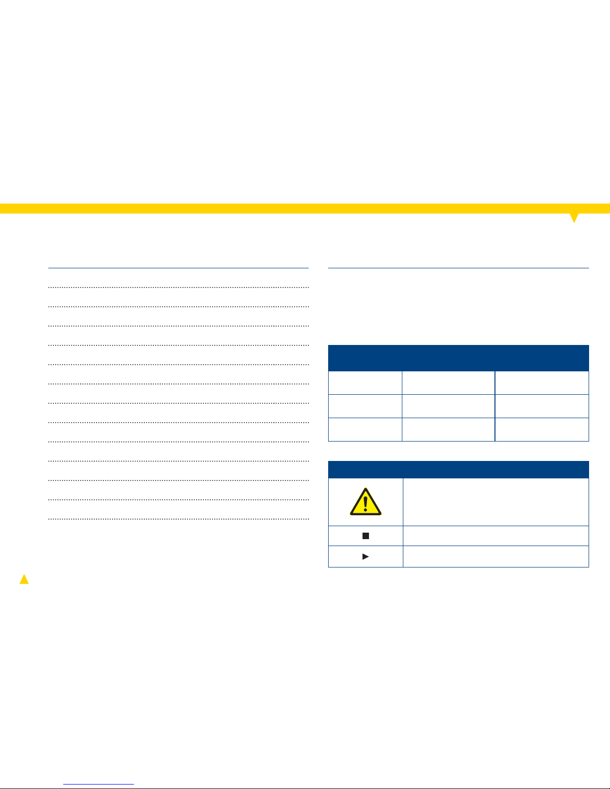
Declaration of conformity 2
Safety, product description 3
Technical specifi cations 5
Installation
* 6
Electrical connection
* 9
Venting
* 11
Speed adjustment
* 11
Mounting cable box 13
Self-learning module 16
Description of functions 17
Servicing
* 18
Replacement
* 20
Faults and remedies 22
These instructions are part of the product, are valid for all
series named and describe how to use the product safely
and correctly during all operating phases.
Danger!
immediate acute
risk
fatal or serious
injury
Warning! potential acute risk
fatal or serious
injury
Careful!
potentially hazardous situation
light injury, damage
to device
Warning labels and symbols
Safety warning sign: Take note of all
information indicated by the safety
warning sign and follow the instructions
to avoid injury or death.
Information
Instruction
Contents
Safety
Chapters marked with * contain illustrations of the pump BWO
155.
Warning label Risk level
Consequences of
non-observance
Symbol Meaning
Page 4

4
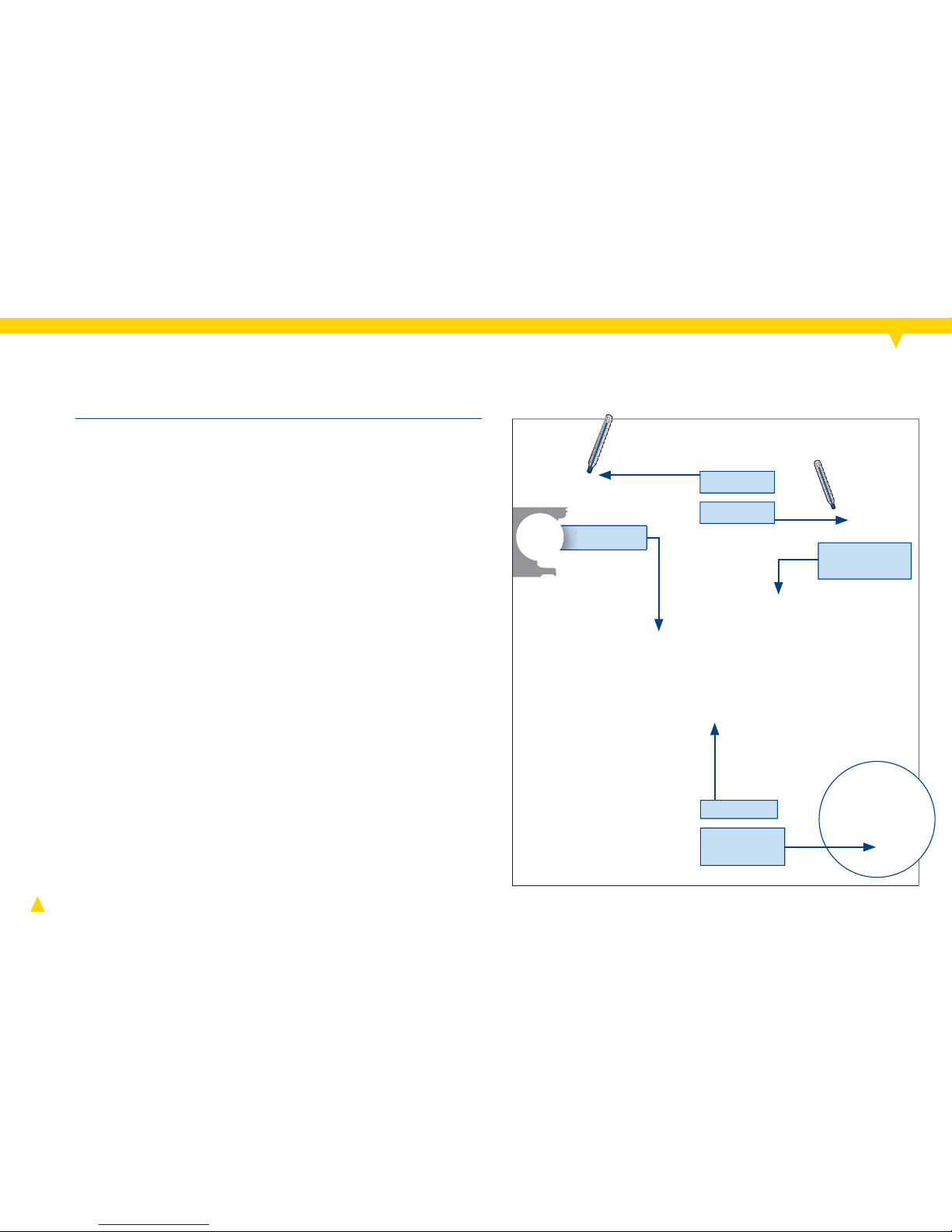
automatically identifi es the consumer’s hot water
consumption patterns within a short time. It identifi es
when hot water is needed and provides it proactively.
Using the button controller, the comfort setting can be
adjusted to the specifi c needs. LED indicators display the
current operating status of the pump.
automatically detects deviations from the “standard”
pattern, e.g. weekends, absence and daylight-savings
time.
automatically detects the time for the thermal
disinfection
1
.
switches the pump off as soon as the pump control
detects that hot water is available in the domestic hot
water (DHW) circuit.
The self-learning module
(also see chapter "Functional description" p. 17)
Product description
The pump BWO 155 SL BlueOne is a domestic hot water
pump with a highly-effi cient electronically commutated DC
motor as drive source. It is built according to the original
VORTEX spherical motor principle and contains a permanent magnetic rotor. The speed of the pump BWO 155 SL is
infi nitely variable.
Installation of the pump may only be performed by quali-
fi ed personnel.
Keep the operating instructions and other applicable docu-
ments complete, in a legible condition and permanently
accessible.
Read the operating instructions and make sure you under-
stand them before working on the pump.
This pump is suitable for drinking water only.
Only operate the pump if it is in perfect technical condition;
only use it as intended, staying aware of safety and risks,
and adhering to the instructions in this manual.
Before carrying out any installation or maintenance work,
disconnect motor from power supply and ensure it cannot
be reconnected unintentionally.
General safety instructions
Page 5
5
P
max
= 10 bar
~ 43 dB(A)
TF 95
(t1 ≤ 95 °C)
t2 ≤ 40 °C
t1 ≤ 95 °C
1~115–230 V
50–60 Hz
Technical specifi cations
In branched pipework without hydraulic balancing, the level
of convenience may be reduced.
The pump run times can be reduced to a minimum with the
BWO 155 SL. This does not contradict DVGW working paper
W 551, since the protection required against the growth of
legionellae is attained through regular thermal disinfection. This is performed automatically by the BWO 155 SL
1
.
Furthermore, if the consumer is absent, regular water
exchange in the pipework is ensured (daily fl ushing).
Scope of delivery
Gaskets and selected union set for pumps with V-type
pump housing
Insulating cover for pump housing
Operating instructions
Cable box with temperature sensor, sensor cable
2
and
detachable cable tie
3 cable ties for attaching the sensor cable
1
Precondition: The hot water boiler has an anti-legionellae function.
2
A 5m long sensor cable is available as an accessory.
Page 6
6
≥ 50 cm
KV 150
RV 153
(1)
(2)
≥ 50 cm
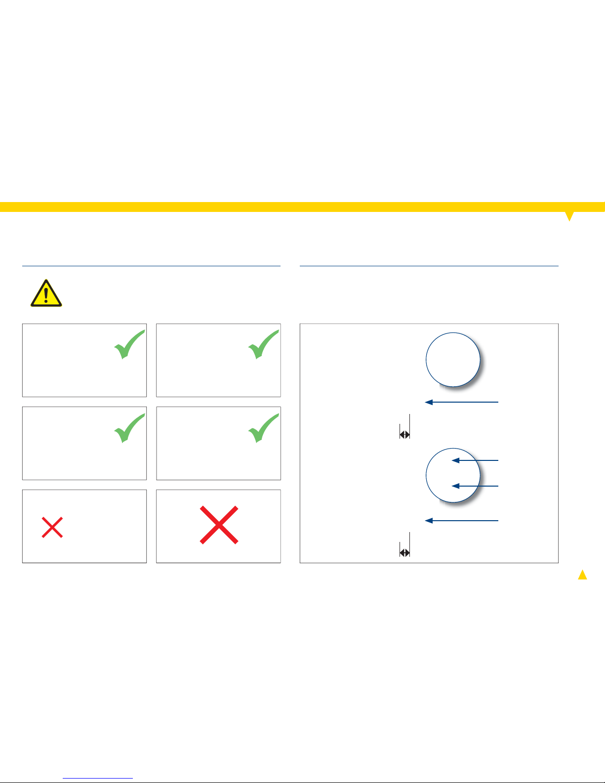
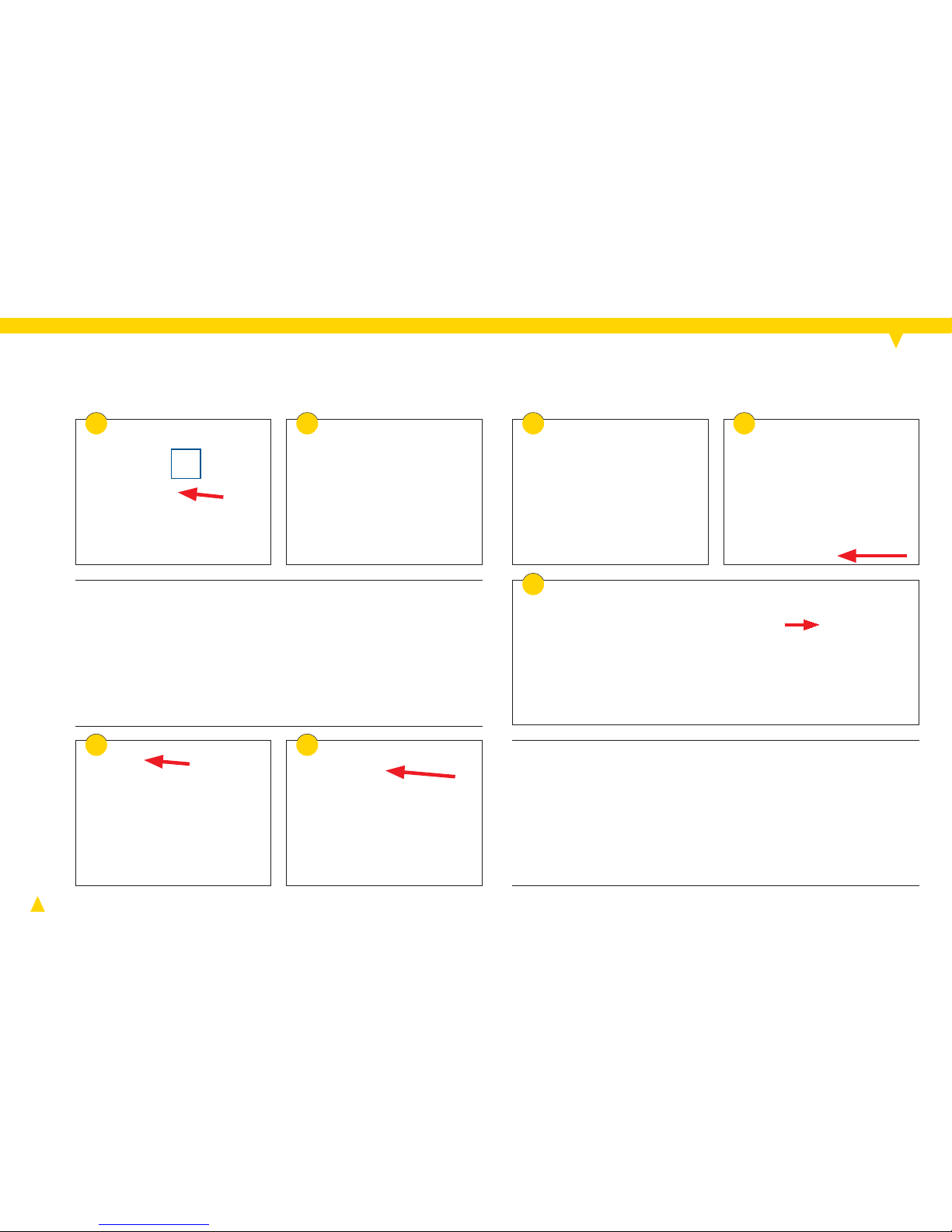
Careful! Damage to device caused by water
intrusion.
► After mounting, ensure that the cable entry
or the cable is pointing downwards (see fi g.).
Installation
A shut-off valve and a non-return valve are already built
into V-pumps (1).
► With R 1/2" pumps (2), build in an additional non-return
valve RV 153 and a ball shut-off valve KV 150.
Page 7
7
++
VORTEX EF 150
= 20 Nm
6 7
98
4 5
3
1
2
Careful! Damage to bearings caused by dry-
running.
► Flush pipework thoroughly with water and
bleed (see fi gs. 1-12).
Installation
Page 8
8
13
= 20 Nm
10 11 12
Careful! Damage to bearings caused by dry-
running.
► Flood the pump before connecting electric-
ity: Open all stop valves slowly (see fi g. 13).
Installation
Page 9

9
230 V~
8,5 - 10 mm
3a 3b 3c
21
The drive of the pump is a DC motor. Thus a protective
conductor is not required.
For AC operation a transformer is integrated in the cap.
Electrical connection
Danger! Danger of electrocution.
► Have all electrical work carried out by
qualifi ed electricians only.
► Turn off the power supply and safeguard it
against being switched back on (see fi g. 1).
► Check to make sure the power is turned off.
Warning! Fire hazard due to electrical
ignition.
► Make sure that the pump is only connected
to the power supply specifi ed on the name
plate.
Note: The pump deletes all commands for automatic starts
if the power supply is shut off.
► The pump requires an independent electrical power
supply. Do not connect the pump to an additional
controller or timer.
► A permanent power supply is possible, alternatively
use a mains plug with IP 44 rating (provide isolator that
separates all poles).
► Cable diameter 0.75 – 1.5 mm²
► Round cable with Ø 5 – 8 mm
► Connection with twisted wires, no wire end sleeves, no
tinned ends
Page 10
10
10
8 9
230 V~
7
5
4
230 V~ 230 V~
230 V~
6
11
The pump will run continuously as long as the sensor
cable is not connected (see fi g. 11).
Electrical connection
Page 11
11
0 100 200 300 400 500 600 700
0,2
0,4
0,6
0,8
1,0
1,2
1,4
2
4
6
8
10
12
14
800 900
Q [l / h]
H [mWS]
n = 2000 - 3000 1/minBWO 155 V
n = 2000 - 3000 1/minBWO 155 R
[kPa]
5x
3 4
1 2
5
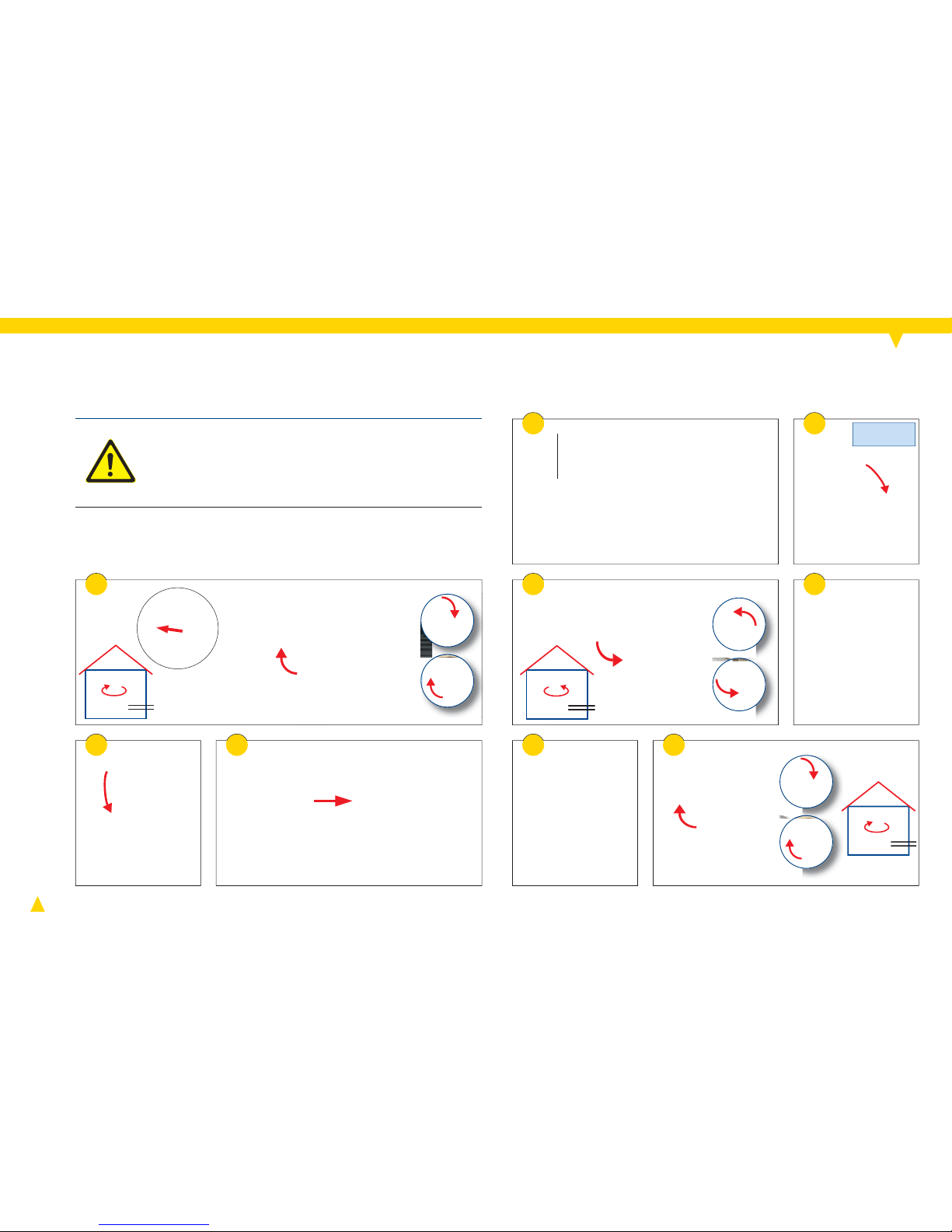
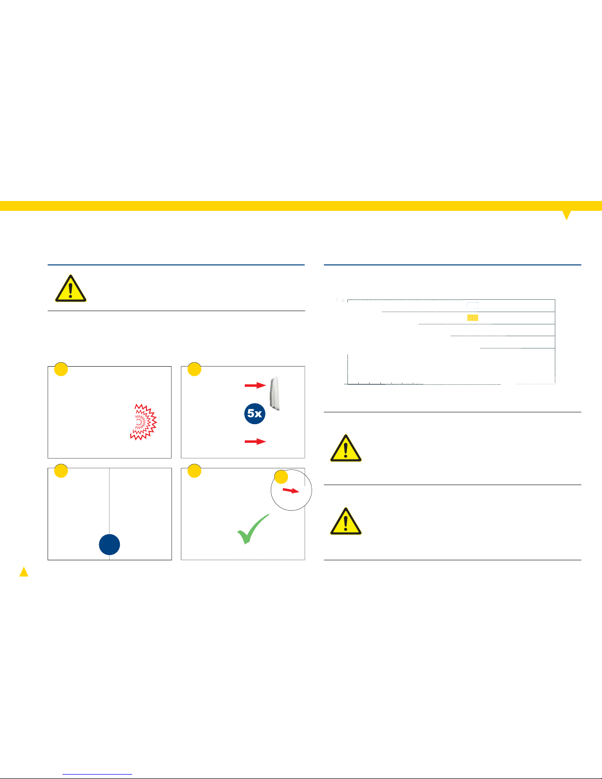
Venting
Warning! Hot surface on pump housing and
motor. Danger of burns!
► Avoid direct contact with pump housing and
motor.
► Ensure that the return line is air-free (see p. 7). Then
act as follows to bleed the pump until it runs noise-free
(alternately):
► Switch the pump on and off several times (see fi g. 2).
► Open a hot water tap several times (see fi g. 3).
Speed adjustment
Danger! Danger of electrocution.
► Before working on the pump, disconnect
power supply and ensure that it cannot be reconnected unintentionally (see fi g. 1, p. 12).
► Check to make sure the power is turned off.
Warning! Hot surface on pump housing and
motor. Danger of burns!
► Avoid direct contact with pump housing and
motor.
The speed is infi nitely variable.
Page 12

12
3
4
2
230 V~
7
5
6
1
Speed adjustment
Page 13
13
20 - 50 cm
2
1
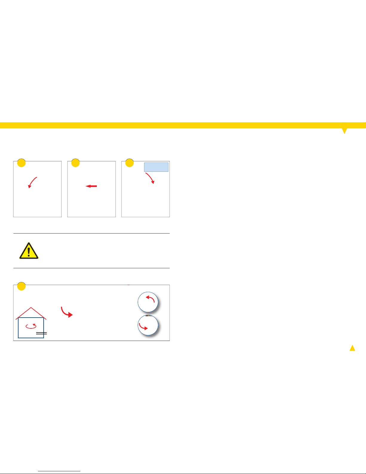
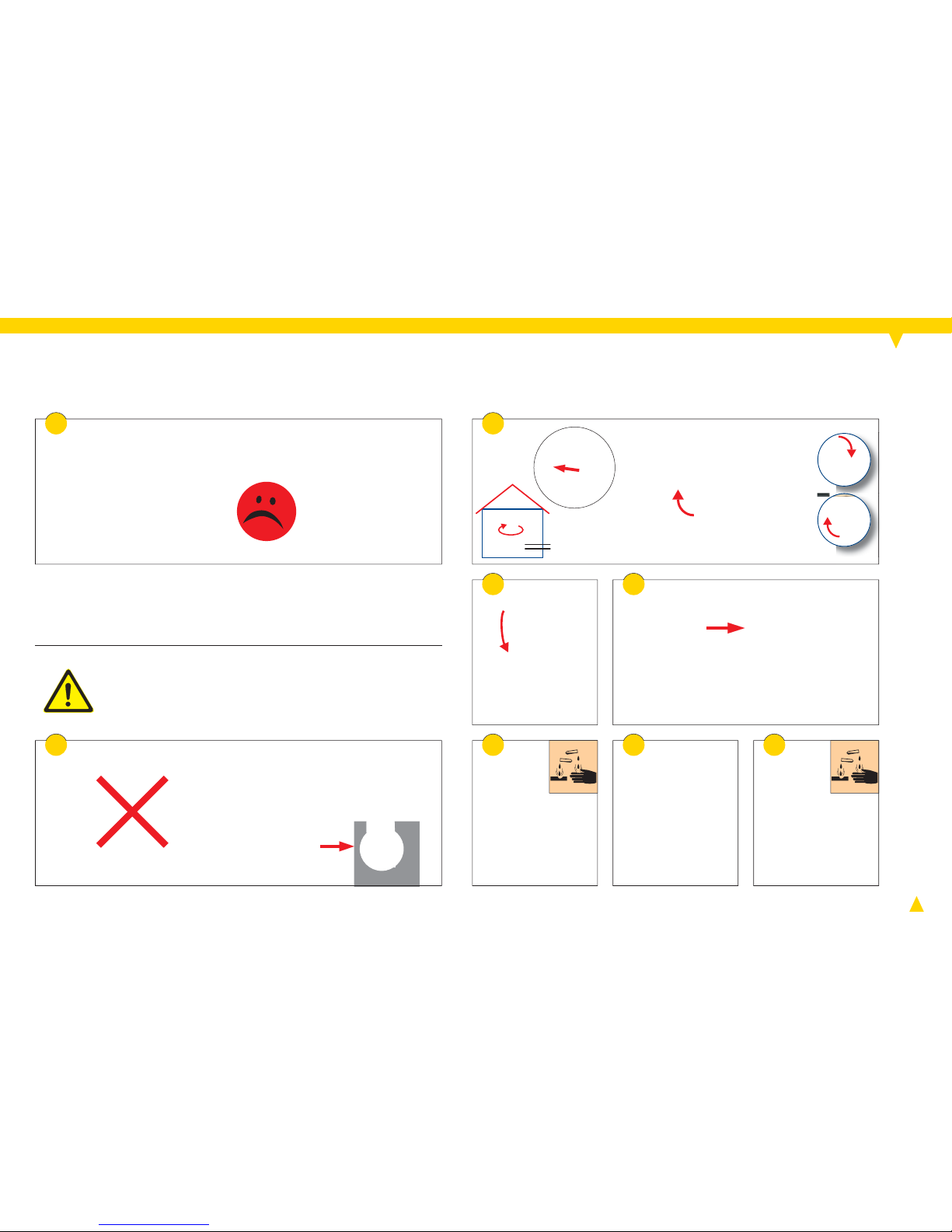
Mounting cable box
Note! Malfunctions of the self-learning module are possible
as a result of incorrect installation.
► Note order of assembly steps (installation sequence).
► Disconnect power supply and ensure that it cannot be
reconnected unintentionally (see fi g. 1).
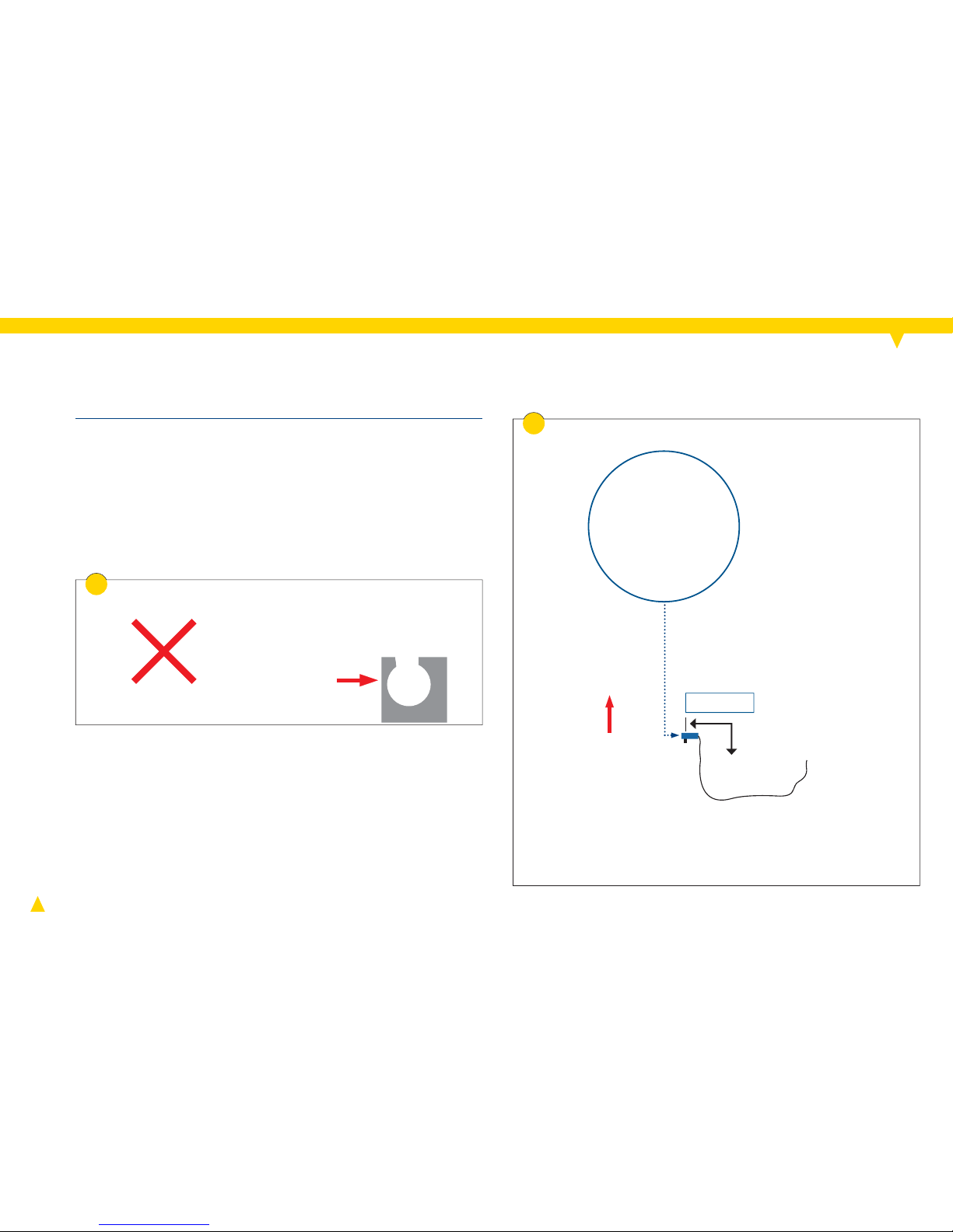
Installation conditions
The cable box must be mounted onto the supply line (hot
water pipe), independently from the type of hot water
generating system used.
Optimal distance of the cable box to the boiler: 20 to
50 cm.
If a mixer valve is present: The cable box can be installed
before or af ter the mixer valve.
Page 14

14
AB
B
3 4 8
6 7
5
A
Warning! Danger of stumbling by loose sensor
cable.
► Secure the sensor cable with the cable ties
after laying (see fi gs. 6 and 14).
Installation sequence
Measure distance between pump and point of installa-
tion of cable box. Only pull as much sensor cable from
the cable box as required. The maximum length of the
sensor cable is 2.50 m. A 5m long sensor cable is available as an accessory.
The sensor cable can only be wound up or unwound
when plug A is still inside the cable box (see fi g. 4).
Mounting cable box
Page 15
15
9 10
11
12
13 14
A
15
Mounting cable box
► Fix cable box to supply line using the cable tie.
► Ensure there is suffi cient thermal contact between the
sensor and the supply line.
Restart: As soon as the power supply has been restored,
the pump and the self-learning module will be ready for
operation, LED indicator 3 will be illuminated (basic setting), and the learning process will begin.
Page 16
16
4
3
5
6
1
1
2
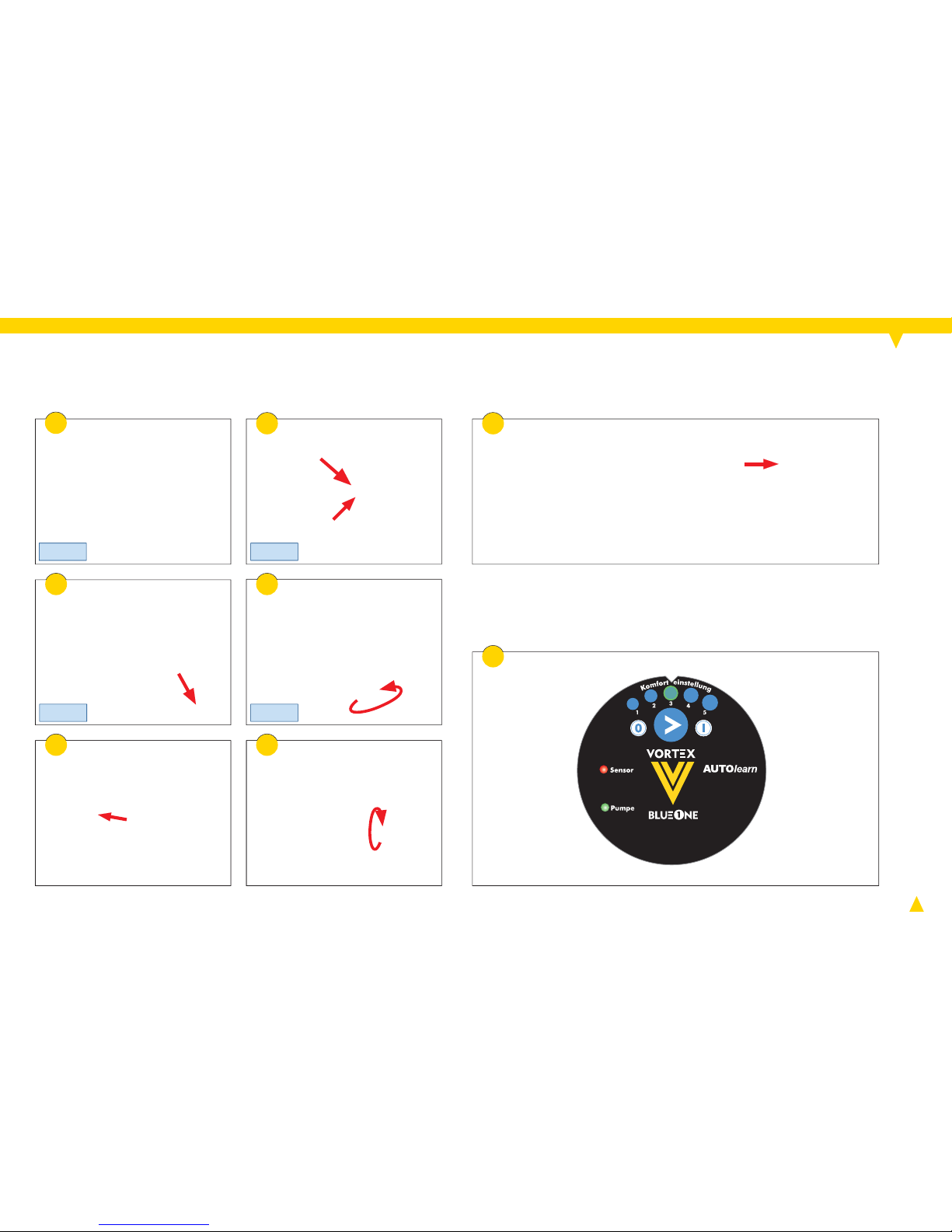
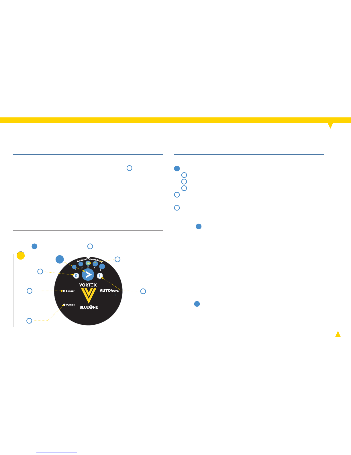
Button and LED indicators :
Legend for fi g. 1:
1
Select the operating mode (clockwise):
2
Comfort setting
3
Continuous pump run
4
Pump stop
5
Pump is running (LED is illuminated green) or it is
switched off (LED is not illuminated)
6
Sensor fault (LED is illuminated red, see p. 23)
Step 1: Maximum energy savings, minimum pump
run times
Step 2: Normal comfor t, short pump run times
Step 3: Basic setting – good comfort, average pump
run times
Step 4: Very high comfort, normal pump run times
Step 5: Maximum comfort, increased pump run times
► Press
1
until the desired operating mode is illuminated.
It will be active immediately.
Changing the operating mode:
Comfort settings:
Press
1
for 5 seconds. All acquired switch-on commands
will be deleted, comfort setting 3 will be set again.
Restoring the factory default settings (reset):
Self-learning module
After establishing a connection to the electric power
grid, the comfort setting 3 will be set (LED 2 is illuminated). This comfort setting is optimal for the majority of
the applications.
► We recommend to wait three weeks before altering the
comfort settings.
► If no hot water is available immediately after opening a
tap, close tap again and wait until circulation has started.
The comfort setting is retained (non-volatile) in case of
power failure.
Page 17

17
How does the pump learn?
A hot water tap is opened. The supply line heats up. This
is detected by the pump through the external temperature
sensor and the point in time of the hot water tap is learned.
For periodic (typical) taps the pump will proactively execute a
pump run (approx. 5 to 15 minutes prior to that point in time).
When does the pump start to run?
For reasons of comfort and independent of DHW drawings,
the pump starts frequently during the fi rst 2 weeks (early
part of the learning phase).
Afterwards, the pump starts in the following cases:
- proactively (at the typical "learned" points in time),
- when hot water is tapped (at not yet learned points in time),
- for a fl ushing or disinfection cycle (see below).
The pump calculates the need for a pump run individually
every single day (Mon to Sun) based on the previous hotwater taps of the last 2 weeks.
How long does the pump run?
The pump will run until the circulation loop is supplied with
warm water (detection through a thermostat in the pump).
The run time depends on the size of the circulation system.
How long does the pump run per day?
The daily runtime depends on the size of the circulation
system, the comfort setting and the tapping behavior of
the consumer. Typically, the pump will run between 1 and 5
hours daily.
Description of functions
How does the disinfection cycle recognition work?
The highest fl ow temperature measured in a given week is
interpreted as the disinfection temperature. At this point in
time, the pump will run for 30 minutes (once per week). If at
any other time of the week a higher supply temperature is
detected, the pump will shift the disinfection cycle to that
point in time.
How is absence detected (vacation detection)?
If no hot water is tapped within 24 hours, the pump will
determine an absence. Proactive pump runs will no longer
occur. A detected disinfection cycle will still be performed
(once per week). Otherwise, the pump will perform a daily
fl ushing cycle (duration: 15 minutes).
How will the return from the absence be recognized?
With 2 hot water tappings within an hour the previously
learned cycle will come into effect again.
How do you delete the learned tappings (reset)?
The self-learning module erases all learned switch-on
commands if the power is interrupted or the button
1
is
pressed for 5 seconds.
Page 18
18
6
4
7 8
3
5
2
1
Danger! Danger of electrocution.
► Before working on the pump, disconnect power
supply and ensure that it cannot be reconnected unintentionally (see fi g. 2).
► Check to make sure the power is turned off.
Note: Damage of sensor cable.
► When removing the motor from the pump housing, pay
attention to the sensor cable (fi xed with cable ties).
Servicing
Page 19

19
5x
16
17
9 10
11
13
14
12
15
= 20 Nm
► Technical support is available from your heating and
sanitary specialist or from Deutsche Vortex.
Servicing
► Ever y time the motor is opened, replace the sealing
ring (see fi g. 9).
► Insert the new sealing ring into the groove in the pump
housing and press slightly into place (see fi g. 10).
Page 20

20
11
5 6 7
8
9 10
= 20 Nm
1 2
3 4
Danger! Danger of electrocution.
► Before working on the pump, disconnect
power supply and ensure that it cannot be
reconnected unintentionally (see fi g. 1).
► Check to make sure the power is turned off.
Motor
Replacement
Page 21

21
1
3
2
► Concluding the exchange: See chapters starting at Elec-
trical Connection, p. 9 and further.
Cap/control module
Danger! Danger of electrocution.
► Have all electrical work carried out by quali-
fi ed electricians only.
► Disconnect power supply and ensure that it
cannot be reconnected unintentionally
(see fi g. 1).
► Check to make sure the power is turned off.
Replacement
► Concluding the exchange: See chapters starting at Elec-
trical Connection, p. 9 and further.
Page 22

22
Pump is not
running: LED
"Pumpe" (pump)
is not illuminated.
Power supply is interrupted. ► Make sure that the power supply is establis-
hed correctly.
Electrical connection,
p. 9.
Cooling down, in case of a detected ab-
sence or if there is no current demand.
► Wait for the next pump start or tap hot
water.
Pump is not
running: LED
"Pumpe" (pump)
is illuminated.
Motor is defective (electrical/electronics). ► Replace motor.
Replacement, p. 20.
Rotor is blocked because the rotor bearing is
defective.
Rotor is blocked by debris. ► Clean wetted parts.
Servicing, p. 18.
LED "Sensor" is
illuminated red.
E xternal sensor is defective. ► Replace the cable box. Mounting cable box,
p. 13 and further
Sensor cable connection is interrupted. ► Check electrical connections (contact
of blue plugs) and replace module, if
required.
Mounting cable box,
p. 13 and further
Pump stops the
rotor continuously.
Air in the pump housing, dr y run protection
is active.
► Bleed the circulation line.
Installation, p. 6 and
Venting, p. 11.
Faults and remedies
► Observe the chapter “Safety” (see p. 3).
Fault Cause Remedy Chapter/page
Page 23

23
The pump "is
not learning” /
insuffi cient DHW
provision.
The circulation is blocked. ► Restore the fl ow.
The cable box is not mounted to the supply
line.
► Mount the cable box to the supply line
(avoid mounting on braces, valves etc.).
Mounting cable box,
p. 13 and further
The cable box is mounted on a non-heat
conducting piece of pipework.
► Use heat conducting pipework material
(metal, plastic, composites).
Mounting cable box,
p. 13 and further
Non-return valve is missing or constantly
open (gravity circulation!).
► Install or replace V-pump housing or the
non-return valve RV 153.
Speed is set too low. ► Increase speed. Speed adjustment,
p. 11 and further.
No hydraulic balancing where there are
branches in the pipework.
► Perform hydraulic balancing or install a
different control module (timer or control
thermostat)
Pipework too extensive; pump rate too low. ► Install a larger DHW circulation pump.
Pump makes
noise.
Air in the pump housing. ► Bleed the circulation line.
Installation, p. 6 and
Venting, p. 11.
Rotor bearing defective. ► Replace the rotor. If the bearing pin is
damaged exchange the motor.
Replacement, p. 20.
Non-return valve is loose. ► Exchange the V-type pump housing or non-
return valve installed behind the pump
(e.g. RV 153).
Installation, p. 6.
Faults and remedies
► Observe the chapter “Safety” (see p. 3).
Fault Cause Remedy Chapter/page
Page 24

BWO
BWO
155 SL
155 SL
199-13 0-287-en · 0 5/14
Original operating instructions
Deutsche Vortex GmbH & Co. KG
Kästnerstraße 6
71642 Ludwigsburg · Germany
Fon: +49(0)7141.2552-0
E-Mail: info@deutsche-vortex.com
www.deutsche-vortex.com
 Loading...