

Vortex BLUEONE BWO 155, BLUEONE BWO 155 ERT, BLUEONE BWO 155 12V, BLUEONE BWO 155 Z Original Operating Instructions
Page 1

90 °C
80 °C
BWO 155 · BWO 155 12V
BWO 155 Z · BWO 155 ERT
Original oper ating
instructions
Deutsche Vortex GmbH & Co. KG
Kästnerstraße 6
71642 Ludwigsburg
Germany
Fon: +49(0)7141.2552-0
E-Mail: info@deutsche-vortex.com
www. deutsche-vortex.com
70 °C
60 °C
50 °C
40 °C
30 °C
20 °C
Page 2
Contents Safety
Safety 2
Product description, declaration of conformity 3
Technical specications 4
Installation 5
Electrical connection 7
Venting 9
Timer 10
Electronic regulating thermostat ERT 12
Speed adjustment 13
Servicing 15
Replacement 17
Faults and remedies 19
These instructions are part of the product, are valid for all
series named and describe how to use the product safely
and correctly during all operating phases.
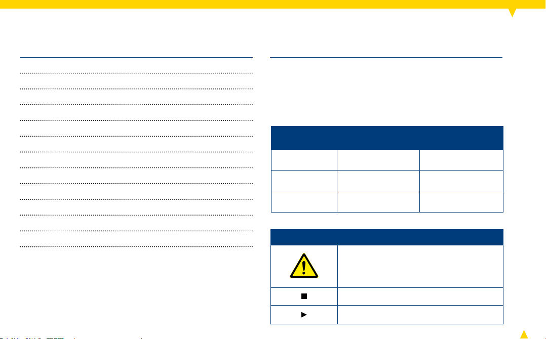
Warning labels and symbols
Warning label Risk level
Danger!
Warning! potential acute risk
Careful!
Symbol Meaning
immediate acute
risk
potentially hazardous situation
Safety warning sign: Take note of all
information indicated by the safety
warning sign and follow the instructions
to avoid injury or death.
Information
Instruction
Consequences of
non-observance
fatal or serious
injury
fatal or serious
injury
light injury, damage
to device
2
Page 3

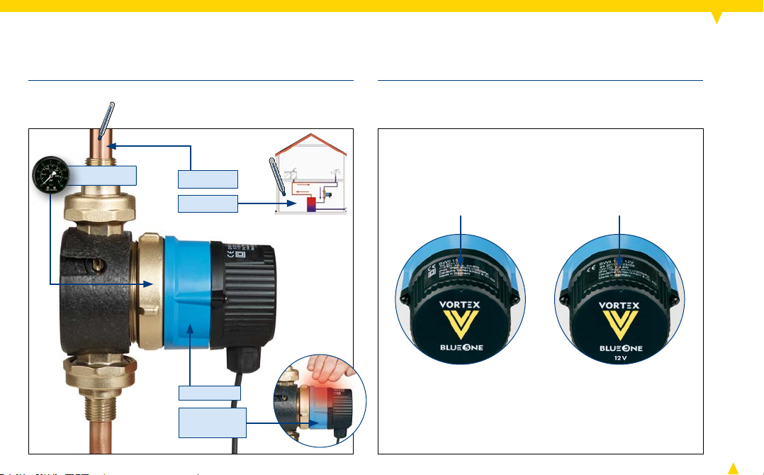
Product description
General safety instructions
Installation of the pump may only be performed by quali-
ed personnel.
Keep the operating instructions and other applicable docu-
ments complete, in a legible condition and permanently
accessible.
Read the operating instructions and make sure you under-
stand them before working on the pump.
This circulator is suitable for drinking water only.
Only operate the pump if it is in perfect technical condition;
only use it as intended, staying aware of safety and risks,
and adhering to the instructions in this manual.
Before carrying out any installation or maintenance work,
disconnect motor from power supply and ensure it cannot
be reconnected unintentionally.
This device may only be used, cleaned or maintained
by children aged 8 years and over; persons with limited
physical , sensory or mental faculties; as well as persons
with limited experience or lack of knowledge; under supervision or after they have been instructed for the safe use of
the device and understand the resulting dangers. Children
are not allowed to play with the device.
3
The pump BWO 155 BlueOne is a domestic hot water pump
with a highly-efcient electronically commutated DC motor
as drive source. It is built according to the original VORTEX
spherical motor principle and contains a permanent magnetic
rotor. The speed of the pump BWO 155 is innitely variable.
Scope of delivery
Gaskets and selected union set for pumps with V-type
pump housing
Insulating cover for pump housing
Operating instructions
Declaration of conformity
This product meets the applicable European directives and
the complementary national requirements and standards.
Conformity has been proven. The declaration of conformity can be retrieved under www.deutsche- vortex.com or
directly from Deutsche Vortex GmbH & Co. KG.
Page 4
Technical specications
P
= 10 bar
max
t1 ≤ 95 °C
t2 ≤ 40 °C
~ 43 dB(A)
TF 95
(t1 ≤ 95 °C)
1~115–230 V
50–60 Hz
12 V=
4
Page 5
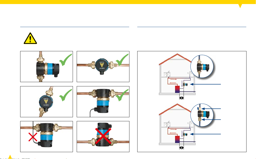
Installation
Careful! Damage to device caused by water
intrusion.
► After mounting, ensure that the cable entry
or the cable is pointing downwards (see g.).
5
A shut-off valve and a non-return valve are already built
into V-pumps (1).
► With R 1/2" pumps (2), build in an additional non-return
valve RV 153 and a ball shut-off valve K V 150.
(1)
≥ 50 cm
KV 150
RV 153
(2)
≥ 50 cm
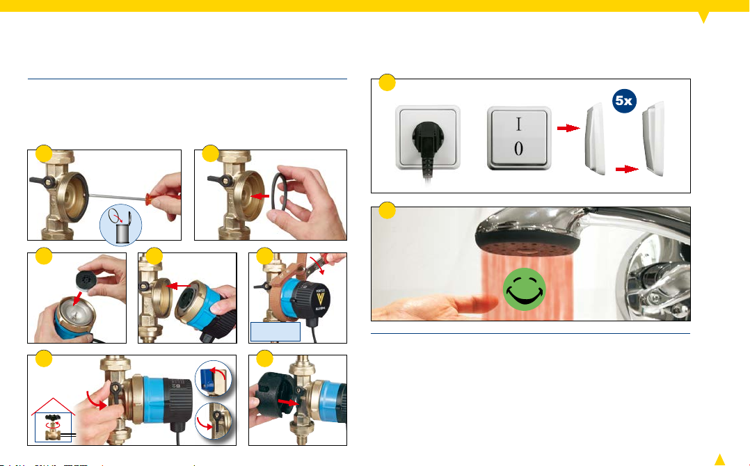
Page 6
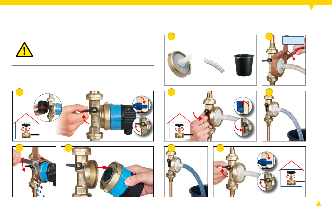
Installation
Careful! Damage to bearings caused by dryrunning.
► Flush pipework thoroughly with water and
bleed (see gs. 1-12).
4 5
VORTEX EF 150
+ +
= 20 Nm
1
2
6 7
983
6
Page 7

7
Installation
10 11 12
Careful! Damage to bearings caused by dry-
running.
► Flood the pump before connecting electric-
ity: Open all stop valves slowly (see g. 13).
13
= 20 Nm
Electrical connection
The drive of the pump is a DC motor. Thus a protective
conductor is not required.
For AC operation a transformer is integrated in the cap.
Danger! Danger of electrocution.
► Have all electrical work carried out by
qualied electricians only.
► Turn off the power supply and safeguard it
against being switched back on (see g. 1).
► Check to make sure the power is turned off.
Warning! Fire hazard due to electrical
ignition.
► Make sure that the pump is only connected
to the power supply specied on the name
plate (see p. 4).
21
Page 8

Electrical connection
3
5
230 V~ 12 V=
► A permanent power supply is possible, alternatively use a mains
plug with IP 44 rating (provide isolator that separates all poles).
► Cable diameter 0.75 – 1.5 mm²
► Round cable with Ø 5 – 8 mm
► Connection with twisted wires, no wire end sleeves, no tinned
ends
Warning! Fire hazard.
► Secure 12 V DC pumps with a 2 A fuse.
4a
4b 4c
230 V~
8,5 - 10 mm
–
+
12 V=
230 V~ 12 V=
6
230 V~
12 V=
7
230 V~
12 V=
8
Page 9

8
230 V~
12 V=
10 11
VentingElectrical connection
9
► Ensure that the return line is air-free (see p. 6).
Then act as follows to bleed the pump until it runs noisefree (alternately):
► Switch the pump on and off several times (see g. 2).
► Open a hot water tap several times (see g. 3).
1 2
Warning! Hot surface on pump housing and
motor. Danger of burns!
► Avoid direct contact with pump housing and
motor.
For pumps with control module:
The BWO 155 Z pump will run continuously.
The BWO 155 ERT pump will run when the preset water
temperature is exceeded.
9
3 4
5x
5
Page 10

Timer
Buttons and LED indicators :
1
5
4
4
10
9
1
Select operating state (clockwise):
2
Continuous
3
Setting mode
4
Operation via time switch
5
Permanent stop
6
Time
7
LED ring of the runtimes (see gure 2, p. 11)
8
Select times (time and runtimes)
9
Pump running (LED lights up) or is off
(LED does not light up)
10
Conrm time/conrm or delete runtimes
When it is connected to the electricity mains for the rst
time, the pump runs continuously (delivered condition –
2, 6
1
2
3
6
7
8
LEDs
Shortest runtime is 30 minutes.
When the power supply is interrupted, the time stops
(no power reserve). The saved runtimes
If the power supply is restored, the pump runs in the
operating state that was last set,
has to be updated.
Setting the time and runtimes:
► Press
► Use
with OK
and 9 light up, see gure 1).
7
are retained.
6
ashes. The time
1
until 3 lights up.
8
to set the red LED to the current time and conrm
10. 9
no longer lights up. The green LED in the
section 0.00 h to 0.30 h ashes.
8
► With
, set the LED to the required runtime and conrm
with OK
Conrm once again with OK
LED ring runs more quickly if
► End setting with
The pump runs according to the set runtimes,
10
. The LED jumps directly to the next runtime.
1
. The saved runtimes are displayed.
10
or skip with 8 (etc.). The
8
is held down.
4
lights
up.
10
Page 11

Timer
Example of a setting (see gure 2):
Current time
6
: for example 9:30 h
(LED in the time window from 9:30 a.m. till 10:00 a.m.)
The pump is not running, LED
Set runtimes
06:00 a.m. - 07:30 a.m.
11:00 a.m. - 01:30 p.m.
7
of the pump:
2
4
9
3
1
11
10 8
9
is off.
03:30 p.m. - 06:30 p.m.
08:00 p.m. - 08:30 p.m.
7
6
4
3
6
1
10 8
09:00 p.m. - 09:30 p. m.
10:00 p.m. - 10:30 p.m.
3
Changing the time:
1
► Press
on the current time
► Conrm with OK
► End setting with
runtimes,
until 3 lights up. Press 8 until the red LED is
6
(see gure 3).
10
.
1
4
. The pump runs according to the set
lights up.
Changing runtimes:
1
► Press
10
until 3 lights up. Conrm current time with OK
(see gure 3). The saved runtimes light up. A runtime
ashes (see gure 4).
► Adding new runtimes: Press
conrm with OK
10
. Repeat process for additional run-
times or end setting with
► Deleting runtimes: Press
to delete ashes, conrm with OK
additional runtimes or end setting with
8
until new runtime ashes,
1
.
8
until the runtime you want
10
. Repeat process for
1
.
Resetting all setting values:
1
► Press
for 5 seconds (see gure 1, p. 10).
Changing the operating state:
1
► Press
(
until the required operating state
2 ,4
or 5) lights up (see gure 1, p. 10).
It is active immediately.
Page 12
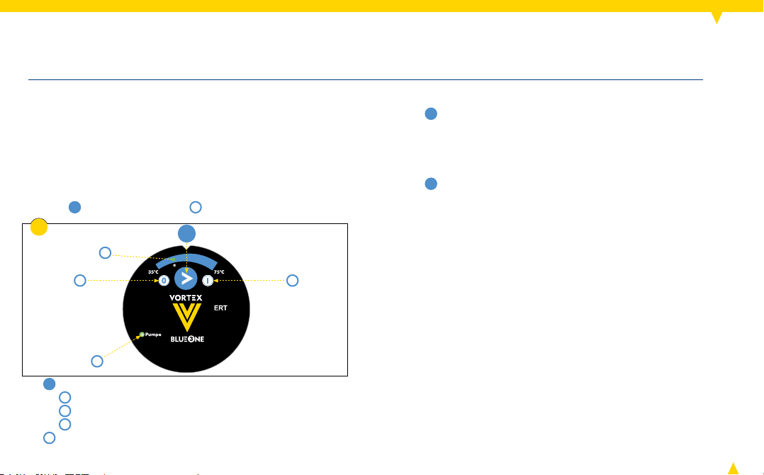
Electronic regulating thermostat ERT
The pump will switch off when the preset temperature is
reached. After the water has cooled down approx. 7°C
the pump will switch back on.
After connection to the electrical power grid 45°C (e) is set
as the switch-off temperature of the pump (see gure 1).
In case of a power outage the preset switch-off tempera-
ture will be conserved.
Button
1
and LED indicators :
1
4
3
5
1
Select the operating mode (clockwise):
2
Continuous pump run
3
Pump stop
4
Switch-off temperature of the pump (e=45°C)
5
Pump is running (LED is illuminated) or switched
2
off (LED not illuminated)
Changing the switch-off temperature:
1
► Press
until the desired switch-off temperature is
illuminated. (9 steps in 5° increments from 35°C to
75°C).
Changing the operating mode:
1
► Press
until the desired operating mode is illuminated.
It will be active immediately.
12
Page 13
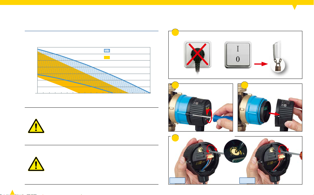
0 100 200 300 400 500 600 700
0,2
0,4
0,6
0,8
1,0
1,2
1,4
2
4
6
8
10
12
14
800 900
Speed adjustment
8
10
12
14
The speed is innitely variable.
1
BWO 155 R
BWO 155 V
H [mWS]
Q [l / h]
Warning! Hot surface on pump housing and
motor. Danger of burns!
► Avoid direct contact with pump housing and
motor.
13
Danger! Danger of electrocution.
► Before working on the pump, disconnect
power supply and ensure that it cannot be
reconnected unintentionally (see g. 1).
► Check to make sure the power is turned off.
n = 2000 - 3000 1/min
n = 2000 - 3000 1/min
[kPa]
2
4
230 V~ 12 V=
3
Page 14

Speed adjustment
5
7
6
14
Page 15

Servicing
1
3
15
4
Danger! Danger of electrocution.
► Before working on the pump, disconnect
power supply and ensure that it cannot be
reconnected unintentionally (see g. 2).
► Check to make sure the power is turned off.
2
6
5
7 8
Page 16
Servicing
► Every time the motor is opened, replace the sealing
ring (see g. 9).
► Insert the new sealing ring into the groove in the pump
housing and press slightly into place (see g. 10).
9 10
16
5x
17
11
14
12
13
= 20 Nm
15
► Technical support is available from your heating and
sanitary specialist or from Deutsche Vortex.
16
Page 17

Replacement
Motor (pictured: BWO 155)
Danger! Danger of electrocution.
► Before working on the pump, disconnect
power supply and ensure that it cannot be
reconnected unintentionally (see g. 1).
► Check to make sure the power is turned off.
5 6 7
1 2
3 4
11
8
9 10
= 20 Nm
17
Page 18

Replacement
► Concluding the exchange: See chapters starting at Elec-
trical Connection, p. 7 and fur ther.
2
3
Cap/control module
Danger! Danger of electrocution.
► Have all electrical work carried out by quali-
ed electricians only.
► Disconnect power supply and ensure that it
cannot be reconnected unintentionally
(see g. 1).
► Check to make sure the power is turned off.
1
► Concluding the exchange: See chapters starting at Elec-
trical Connection, p. 7 and fur ther.
18
Page 19

Faults and remedies
► Observe the chapter “Safety” (see p. 3).
Fault Cause Remedy Chapter/page
Pump not running.
"Pump" LED does
not light up*.
"Time" LED
a shes*.
Pump is not
running: LED
"Pumpe" ( pump)
is illuminated.*
Pump stops the
rotor continuousl y.
Pump makes
noise.
*only Pumps BWO 155 Z and/or BWO 155 ERT
Power supply is interrupted. ► Ensure correct power supply.
Time switch function does not start the
pump. (BWO 155 Z)
► Check "Operating state" LED.
► Wait for next pump start.
Timer, p. 11
► Change time setting.
Temperature function does not start the
pump (BWO 155 ERT).
Power supply was interrupted. ► Update time. Timer, p. 11
Motor is defective (electrical/electronics). ► Replace motor.
Rotor is blocked because the rotor bearing is
► Change shutdown temperature or wait for
next pump start.
Electronic regulating
thermostat ERT, p. 12
defective.
Rotor is blocked by debris. ► Clean wetted parts. Maintenance, p. 15
Air in the pump housing, dr y run protection
is active.
Air in the pump housing. ► Bleed the circulation line. Installation, p. 6 and
► Bleed the circulation line. Installation, p. 6 and
Venting, p. 9
Venting, p. 9
Rotor bear ing defective. ► Replace the rotor. If the bearing pin is
Replacement, p. 17
damaged exchange the motor.
Non-return valve is loose. ► E xchange the V-type pump housing or non-
Installation, p. 5
retur n valve installed behind the pump
(e.g. RV 153).
19
Page 20

BWO 155 · BWO 155 12V · BWO 155 Z · BWO 155 ERT
Original operating instructions
Deutsche Vortex GmbH & Co. KG
Kästnerstraße 6
71642 Ludwigsburg · Germany
Fon: +49(0)7141.2552-0
E-Mail: info@deutsche-vortex.com
www.deutsche-vortex.com
199-13 0-265-en · 10/17
20
 Loading...