

Page 1

User Guide for Vortex 851R printer (R13)
28-May-2014
-1-
Page 2

Copyright statement
© 2013 RTI Digital, This document, attachments, and information contained herein are the
confidential and proprietary property of RTI Digital and their suppliers. As such, this document,
attached files, and information contained herein are subject to all nondisclosure and proprietary
information agreements currently in effect with your organization. Copies of this document, any
portion of this document, or attachments may not be transmitted or disclosed to any third party
without the prior written permission of RTI Digital.
© 2013 RTI Digital All content is the confidential property of, or licensed to, RTI Digital (“RTID,”
“we,” or “us”) and is protected under Hungarian and Foreign copyright, trademark and other
intellectual property laws.
-2-
Page 3

Contents
Copyright statement ...................................................................................................................... 2
1. Introduction .......................................................................................................................... 7
1.1. Introduction to MemjetR print technology ............................................................................. 7
2. Printer parts and their functions ................................................................................................. 9
2.1. Printer ................................................................................................................................. 9
2.2. Print engine ......................................................................................................................... 9
2.3. Printhead ........................................................................................................................ 9
2.4. Printhead Cartridge Dock .................................................................................................... 9
2.5. Print Mechanism .......................................................................................................... 10
2.6. Cutter ................................................................................................................................ 10
2.7. Ink Cartridges .................................................................................................................... 11
2.8. Ink Connection Ports ......................................................................................................... 13
2.9. Ink Delivery System (IDS) .................................................................................................. 13
2.10. Bulkhead Assembly ......................................................................................................... 13
2.10. Maintenance Module ................................................................................................ 15
2.12.1. Wiper station ............................................................................................................ 17
2.12.2. Printing platen ........................................................................................................... 17
2.12.3. Capping/spittoon station ............................................................................................ 18
2.12.4. Printhead servicing events ..................................................................................... 18
2.13. Print Zone ........................................................................................................................ 18
2.14. Onboard Print Engine Controller (OmniPEC) and Main Board ............................................ 18
2.15. The Control System.......................................................................................................... 19
3. Installing the Printer ............................................................................................................ 20
3.1. Choose a location .............................................................................................................. 20
3.2. Unpacking and Setup ........................................................................................................ 20
3.3. Checking the contents .................................................................................................. 20
3.4. Connecting the Vortex 851R .......................................................................................... 21
3.5. Setting up the Printer .................................................................................................... 23
3.5.1 Maintenance Module (MM) ......................................................................................... 23
3.5.2 Installing Ink Cartridges ............................................................................................... 25
3.5.3. Installing the Printhead ............................................................................................... 26
3.5.5. Media Handling .......................................................................................................... 32
3.6. Connect the printer to a computer .................................................................................... 33
-3-
Page 4

3.6.1. Direct connection to a personal computer ................................................................... 33
3.7. Installing the Printer Driver ........................................................................................... 34
3.7.1. Driver Specifications – Printer Preferences................................................................. 42
3.8. Label printing, generating print jobs. .................................................................................. 46
3.8.1. Printing labels from softwares ..................................................................................... 46
3.8.2. Printing labels from print jobs. ..................................................................................... 46
3.9.0.Printers Buttons ........................................................................................................... 47
3.9.1. Buttons and Led signals .............................................................................................. 48
4. Toolbox ................................................................................................................................... 49
4.1.User Interface .................................................................................................................... 49
4.2.Diagnostics ........................................................................................................................ 50
4.3.Ink Usage ........................................................................................................................... 52
4.4.Network configuration ....................................................................................................... 53
4.5.Service Menus ................................................................................................................... 54
5. Maintenance Guide ................................................................................................................. 55
5.1. Maintenance Overview ................................................................................................. 55
5.2. Standard Maintenance ................................................................................................. 55
5.2.1. Daily Maintenance Tasks ............................................................................................ 57
5.2.2. Bi-Weekly Maintenance Tasks .................................................................................... 59
5.2.3. Monthly Maintenance Tastks ..................................................................................... 62
5.2.4. Annual Maintenance Tasks .................................................................................... 68
5.2.5. As Needed Maintenance Tasks .................................................................................. 77
6.Troubleshooting ....................................................................................................................... 88
6.1. Maintenance Module (aka Service Station) Troubleshooting ............................................. 88
6.2. Printhead Troubleshooting ................................................................................................ 89
6.3. Print quality problems ........................................................................................................ 89
6.4. Vortex 851R Troubleshooting Guide ................................................................................... 90
GENERAL ............................................................................................................................ 90
Documents to read before (available on ftp) ......................................................................... 90
Checklist before doing any support ...................................................................................... 90
Troubleshooting Tools ......................................................................................................... 91
Installing and checking the Custom Firmware routines ......................................................... 91
Dead engine,EWS,Firmware ................................................................................................ 93
How to detect: ..................................................................................................................... 93
-4-
Page 5

How to detect: ..................................................................................................................... 93
How to fix: ........................................................................................................................... 93
How to detect: ..................................................................................................................... 93
How to fix: ........................................................................................................................... 93
PRINT ENGINE: ERROR MESSAGES ..................................................................................... 94
Crit 63 03-phead offline cancelpage ..................................................................................... 94
CARTRIDGE_MISSING_X .................................................................................................... 94
DATA_PATH_UNDERRUN ................................................................................................... 94
Fatal 71 02 offline cancelpage .............................................................................................. 95
How to detect: ..................................................................................................................... 95
How to fix: ........................................................................................................................... 95
How to fix: ........................................................................................................................... 95
Explanation: ........................................................................................................................ 95
How to detect: ..................................................................................................................... 96
How to fix: ........................................................................................................................... 96
How to detect: ..................................................................................................................... 96
How to fix: ........................................................................................................................... 96
MAINTENANCE_BUSY ........................................................................................................ 97
How to detect: ..................................................................................................................... 97
How to fix: ........................................................................................................................... 97
How to detect: ..................................................................................................................... 97
How to fix: ........................................................................................................................... 98
PAPERPATH_CUTTER_ERROR ............................................................................................. 98
PAPERPATH_FEED_TIMEOUT ............................................................................................. 98
PAPERPATH_PAPERJAM .................................................................................................... 98
6.5. Print Quality Issues ........................................................................................................... 99
Color Mixing (CM)................................................................................................................ 99
Examples for Color Mixing ................................................................................................. 100
Streaking (SR) ................................................................................................................... 109
Dot Misplacement (DP) ...................................................................................................... 115
Banding (BD) ..................................................................................................................... 118
Other General Print Quality Errors (GE)............................................................................... 124
Paper Handling (PA) .......................................................................................................... 133
Ink Delivery System (ID) ..................................................................................................... 138
-5-
Page 6

Paper Cutting (PC) ............................................................................................................. 140
Firmware Error Messages (ER) .......................................................................................... 141
Maintenance Module (MM) ............................................................................................... 143
7. Printer Specifications ............................................................................................................ 144
-6-
Page 7

1. Introduction
The purpose of this manual is to describe the operation of the Vortex 851R label printer. The
first section provides and overview of the Memjet™ print technology to make you familiar with the
terms and basics of this new technology that forms the basis of the Vortex 851R printer series. The
following sections walk you through the installation steps, explain the components of the printer and
their roles, and then teach you how to operate your printer. The manual ends with a maintenance
and troubleshooting guide.
Introduction to MemjetR print technology
1.1.
Memjet™ Technology is a revolutionary printing technology developed by Silverbrooks
Research (Sidney, Australia). The core of this technology is a full paper width printhead capable of
printing the entire page width at the same time without head movement. The result of this setup is a
breakthrough 12 inch (305 mm) per second printing speed. The printhead is manufactured with stateof-the art semiconductor technology; an A4 head contains 70,400 nozzles delivering 1600 dpi native
resolution at full colour. The nozzles are arranged in 10 rows having 2 rows for each ink channels.
The fixed head spans the width of the label and feeds an entire label at a time similar to a laser
printer. This architecture dramatically improves performance and ink drop placement accuracy
during printing, while decreasing noise and vibration.
Figure 1 Printing with a traditional moving head and with the
Memjet printhead.
Figure 2 The Memjet 8.5” printhead cartidge showing the ink inlet, outlet ports,
various print-related parts and the printhead.
-7-
Page 8

a)
b)
Figure 3 The Memjet printhead contains 70,400 nozzles in 10 rows (brown stripe in Figure a). An electron
microscope image of a single nozzle (Figure b).
The small size of the nozzles results in very small (1-2 picolitre) paint drops, approximately
14 micron drop diameter on paper, effectively achieving the highest print resolution the human eye
can see.
Printing with this type of precision requires many technical details to be solved including printhead
cooling, using special fast drying inks, feeding paper accurately, controlling the operation of the unit,
etc. A unique property of Memjet printing is the special print processor that uses a custom hardware
print pipeline processing engine to render images at a very high speed. The level of technical
standards are reflected by the fact that Silverbrooks Research hold 2500 patents related to Memjet
Technology along with another 2000 pending.
-8-
Page 9

Picture of the
Print E
ngine
Picture of the Print
head
2. Printer parts and their functions
2.1. Printer
The Vortex 851R printer is a state of the art Memjet printer designed for maximum
usability and performance. The major components of the printer are the print engine, the
controller and the control panel.
2.2. Print engine
The print engine is the heart of the Vortex 851R printer. It is responsible for the actual
print process. The major subsystems of the engine are the mechanics (paper transport), ink
delivery system (including print head and ink tanks), the print controller and a paper cutter.
The Vortex 851R controller is responsible to control the operation for the print engine. You
do not need to access and use the print engine directly except when changing print heads
and ink tanks.
2.3. Printhead
2.4. Printhead Cartridge Dock
The printhead cartridge dock positions the page-wide, static, high-speed Memjet
printhead in the correct location to maintain correct position with the print zone.
-9-
Page 10

Picture of Fluidic Connectors and Memjet Printhead Cartridge
2.5. Print Mechanism
During printing, the print mechanism moves the paper through the print zone below the
static printhead.
2.6. Cutter
The NorthStar cutter is designed to provide a complete cut of continuous media in the
crossweb direction. This will provide the ability to singulate labels and enable a break in
continuous media to allow servicing of the printhead.
The cutter has a design target of providing a 400,000 cut life on thin tag media. Cuts are
expected to execute in 0.4 seconds at up to 80 8.5inch cuts/minute.
The cutter unit can be removed or replaced, if necessary, without affecting the
performance of the NorthStar.
-10-
Page 11

2.7. Ink Cartridges
Vortex 851R Series Printers use a single Printhead Cartridge and five Ink Tanks (two
Black, one Cyan, one Magenta, and one Yellow). During installing the ink cartridges the
Printer should be turned off.
Picture of the ink cart r idge
-11-
Page 12

Picture of Ink Cartridge Cross - Section
Picture of Ink Cartridge Cross - Section with Air Vent Path Detail
-12-
Page 13

2.8. Ink Connection Ports
Ink connection ports allow the connection of the external ink supply houses
to the print engine. Unique, zero insertion-force, ganged connectors allow all 10
ink hoses to be engaged with the printhead in one movement. The printhead can
be removed or installed without disconnecting any of the ink hoses.
2.9. Ink Delivery System (IDS)
The Ink Delivery System (IDS) is a complex system designed to cleanly and reliably
deliver ink to the printhead while minimizing color mixing, drop weight variation, and
dehydration.
The major components of the Ink Delivery System (IDS) are:
• The disposable ink cartridges
• The printhead
• The tubing
• The peristaltic pump
• The pinch valve assembly
• The QA and ink level sensing electronics
• The buffer box
2.10. Bulkhead Assembly
The bulkhead assembly includes the ink cartridges, the septum for connecting to the
bulkhead plate, ink level PCAs, the QAI chip for each ink cartridge, and the buffer boxes for
each ink cartridge.
-13-
Page 14

Other IDS Components
Picture of Bulkhead Assembly
Picture of Other IDS Components
-14-
Page 15

Picture of the
Maintenance Module
2.10. Maintenance Module
Aka Service Station (SS)
The multi-station, maintenance module (MM) maintains and cleans the printhead by
wiping off waste ink and contamination. In addition, the MM assists with printing by priming
the printhead, as well as protecting it when not in use, and guiding the paper as it passes
under the printhead.
The maintenance module (MM) is a sled that contains stations for wiper, cap/spittoon, and
print zone platen.
To position the correct station into place, a stepper motor moves the sled horizontally,
and a DC motor moves the sled vertically.
The maintenance module:
•
Cleans the printhead of excess ink and debris.
•
Keeps the printhead protected and hydrated while not in use.
•
Provides a safe place to spit ink that is used to keep the nozzles clear.
•
Provides a suitable base for supporting the media during printing. This is done with
the print zone platen station.
-15-
Page 16

Picture of Maintenance Module (MM) Assembly (exploded view)
The maintenance module should be replaced as part of annual maintenance or after printing
one million inches.
NOTE: The maintenance module is not intended to be end-user serviceable, although it is a
service part for technicians.
-16-
Page 17

Picture of the wiperstation
2.12.1. Wiper station
The printhead must be wiped to remove ink cross-contamination and particulates. The
cylindrical wiper rotates to wipe the entire width of the printhead. The roller rotates for the
duration of the lift-dwell-lower cycle. The intent is not to merely blot the nozzles but to have
functionally translational wiping. The wiper is programmable and can be rotated numerous
times to perform multiple wiping operations. Once wiping is complete the station drops back
down. A metal transfer roller cleaned by a doctor blade helps remove ink from the wiper. The
removed ink dries or evaporates within the wiper station. When the wiper becomes
contaminated to such an extent that it is no longer effective, the wiper must be replaced by
unlatching the two wiper retaining clips. These clips can be released while the maintenance
module is in the wipe position.
2.12.2. Printing platen
The platen provides a smooth writing surface and the correct spacing between the
media and the printhead. During printing, the paper below the printhead is maintained at a
fixed dive angle from the drive roller nip and platen below the nozzles to ensure print quality.
Along the center of the platen there are four Porex (tm) micro sponges to collect ink
overspray.
Picture of Printing platen
-17-
Page 18

2.12.3. Capping/spittoon station
The printhead should not be allowed to dry out after priming. The cap station is used
when the printer is idle. The cap station limits evaporation from the printhead by sealing
around the nozzles and maintaining a humid environment. The cap is an elastomer seal that
fits around and over the printhead nozzles. It is held against the printhead by the lift springs
on the maintenance module. The cap aligns with the printhead by features at each end of
the maintenance module. The spittoon portion of the station has a waste ink receptacle used
to capture ink ejected during maintenance processes. The used ink wicks and drains into
the waste tank. The wicking bar is a plastic frame and channel of absorbent material. The
absorbent material can be replaced by trained service personnel.
Picture of Capping/spittoon stati on
2.12.4. Printhead servicing events
The printhead requires cleaning after any of the following events occur:
A new printhead is installed and primed
The printhead is removed and then replaced
The printhead is primed or re-primed with ink
The printhead is showing signs of contamination
Be aware that ink is used by the print engine during printhead maintenance as well as
during printing. All waste ink from the printhead nozzles is contained by the maintenance
carousel, either in the spittoon (holds waste ink generated by priming/cleaning) or in the
platen (holds waste ink generated during printing). Therefore, periodic maintenance will be
required to remove the waste ink.
2.13. Print Zone
The clamshell design allows for accessibility during paper loading and paper jam
clearance in the print zone.
2.14. Onboard Print Engine Controller (OmniPEC) and Main Board
The OmniPEC controls all electronic aspects of the printing and print engine operation. The
custom 95-pin WaveTech connector connects the printhead to the printhead board, which is
-18-
Page 19

connected by cables to the OmniPEC main board. The OmniPEC allows connections to paper
motors, ink level sensors, ink pump and additional sensors.
• Dual resolution file format to
• achieve crisp Print Quality (PQ) yet
• reasonable file size
• 1600 dpi lossless text expansion
• 800 dpi contone JPEG expansion
• Two processors: 650MHz RISC CPU with customized HW assist (image processing
focus) and 192MHz SPARC CPU dedicated to the printing pipeline
• Dedicated printing pipeline in HW
• Real-time JPEG compression
• Color Space conversion
• Half-toning
• Dead nozzle compensation
• Printhead data formatting
•
2.15. The Control System
The Printer engine is controlled by the OmniPEC, the Quality Assurance Infrastructure
(QAI), and the firmware.
Full-page array printing:
• Calculates 900 million drops/sec
• Drives 70,400 nozzles on the printhead
• JPEG expansion in hardware
• On-chip memory
• Extensive motor control and I/O
• Xscale – compatible 650 MHz CPU
• > 40 million transistors
• USB 2.0
-19-
Page 20

3. Installing the Printer
4.
3.1. Choose a location
The Vortex 851R should be placed on a properly levelled worktable or cabinet which is
able to handle the printer’s weight and minimum 61 cm (24 inch) wide.
3.2. Unpacking and Setup
The printer is shipped in a strong cardboard or wooden box. Before opening the box, check
that the box is not damaged in any way and was not turned upside down during shipment. If
signs of damage are found, contact your reseller and inspect the box together.
If the box is undamaged, carefully cut the tape on the box, open the box. Before taking the
printer out of the box, make sure a strong and level work surface is prepared for the printer.
NOTE: The printer is heavy. Never attempt to lift and take it out of the box on your own as it can
cause lasting injuries. The printer should always be lifted by two persons.
Place the printer on the desk and inspect that no damages are found on the unit.
Unpack the unwinder and the optional rewinder units and place them on the desk next to
the printer.
3.3. Checking the contents
Check the parts list to ensure you have received all required components. If the shipment is
complete, proceed to the next chapter.
Vortex 851R Printer
1 set of CMYKK ink cartridges (5 cartridges per set)
1 printhead
1 service station
1 main power cable
1 paper guide
Unwinder (Rewinder optional)
-20-
Page 21

Printer and co n t ents
Rewinder/Unwinder
3.4. Connecting the Vortex 851R
Make sure the printer is used with the mains cable suited to the requirements of the
electrical system of your country. The internal power supply in the Printer is rated 115 to
240VAC, 50/60 Hz.
Insert the cable into the printer first. The cable connector should sit in the socket
securely.
Insert the cable into the mains socket.
-21-
Page 22

CAUTION
Do not use an outlet that shares the same circuit with large electrical machines or
appliances
Turning Power On/Off
Powering Up:
1. Turn on the main switch and
2. Press the Main Power Button on top of the Printer.
Powering Down Printer:
1.
Press Main Power button on the top of the Printer, and wait until the engine is
turned off.
2.
And turn off the machine with the main switch.
OR
1. Open the Toolbox and press ’Shutdown’.
2. Wait for the printer to stop processing, and the toolbox write
out the printer not responding
3. Switch off the mainswitch.
CAUTION
Whenever powering down the unit NEVER:
1.) Never remove the power cable during the shutdown process
2.) Never switch off the printer with the Main Power Button when the engine is still running
-22-
Page 23

3.5. Setting up the Printer
After the printer has passed inspection, install the maintenance module, the printhead,
and the ink cartridges, as explained in the following sections.
To set up the printer you need to do the following:
1.
Install the Service Station (if shipped as a separate unit)
2.
Install the ink cartridges
3.
Install the printhead
4.
Turn on the Printer
5.
Unwinder setup
6.
Load label media
7.
Install the printer driver
3.5.1 Maintenance Module (MM)
In case your printer is shipped with a MM as a separate unit, before switching on the
printer, you need to install the MM (After module has passed inspection).
Service Station (aka Maintenance Module)
The Service Station cleans the Printhead Cartridge of excess ink and debris, keeps the
Printhead hydrated and protected when not in use, captures ink used to keep nozzles clear,
and acts as a base to support media during printing.
CAUTION
Make sure latches on the Wiper Roller are properly closed before installing the
Maintenance Module
Installation steps:
• Unpack the Maintenance Module
• Check that each part of the station is complete and functional
• Open the printer and the ink tank cover
• Open the print engine clamshell
• Locate the MM ribbon cable
• Connect the ribbon cable to the MM connector at the back of the service station
• Insert the station into the print engine
-23-
Page 24

The Service Station fits in the port immediately above the Ink Tank Station.
1. Plug in the white flat flex cable to the motor PCA on the maintenance module.
Slide the Latch open on the Maintenance Station Circuit Board:
Plug the ribbon connector (blue side up) into the space under the Latch than close the Latch:
2. Slide in the connected Service Station.
3. Slowly turn the gear on the print engine until the maintenance module engages.
-24-
Page 25

4. Close the clamshell gently to avoid causing vibration on the printhead
NOTE: The MM must be perfectly aligned with bar to prevent misalignment!
3.5.2 Installing Ink Cartridges
Vortex 851R Series Printers use a single Printhead Cartridge and five Ink Tanks (two
Black, one Cyan, one Magenta, and one Yellow). During installing the ink cartridges the
Printer should be turned off.
• Remove the ink tanks from the shipping box.
• Open the ink tank latches in the front of the printer by pushing the bottom of the
latch upward. The latch has a marker for signalling the place of the C, M, Y and K
tanks. (The reason why K is used for Black: in RBG color mode B is reserved for
Blue)
• Locate the place where each tank should go than slowly but firmly push the tank
into the tank socket. The pressure in the ink tanks and the septums may prevent the
cartridge to fully engage for the first insertion.
-25-
Page 26
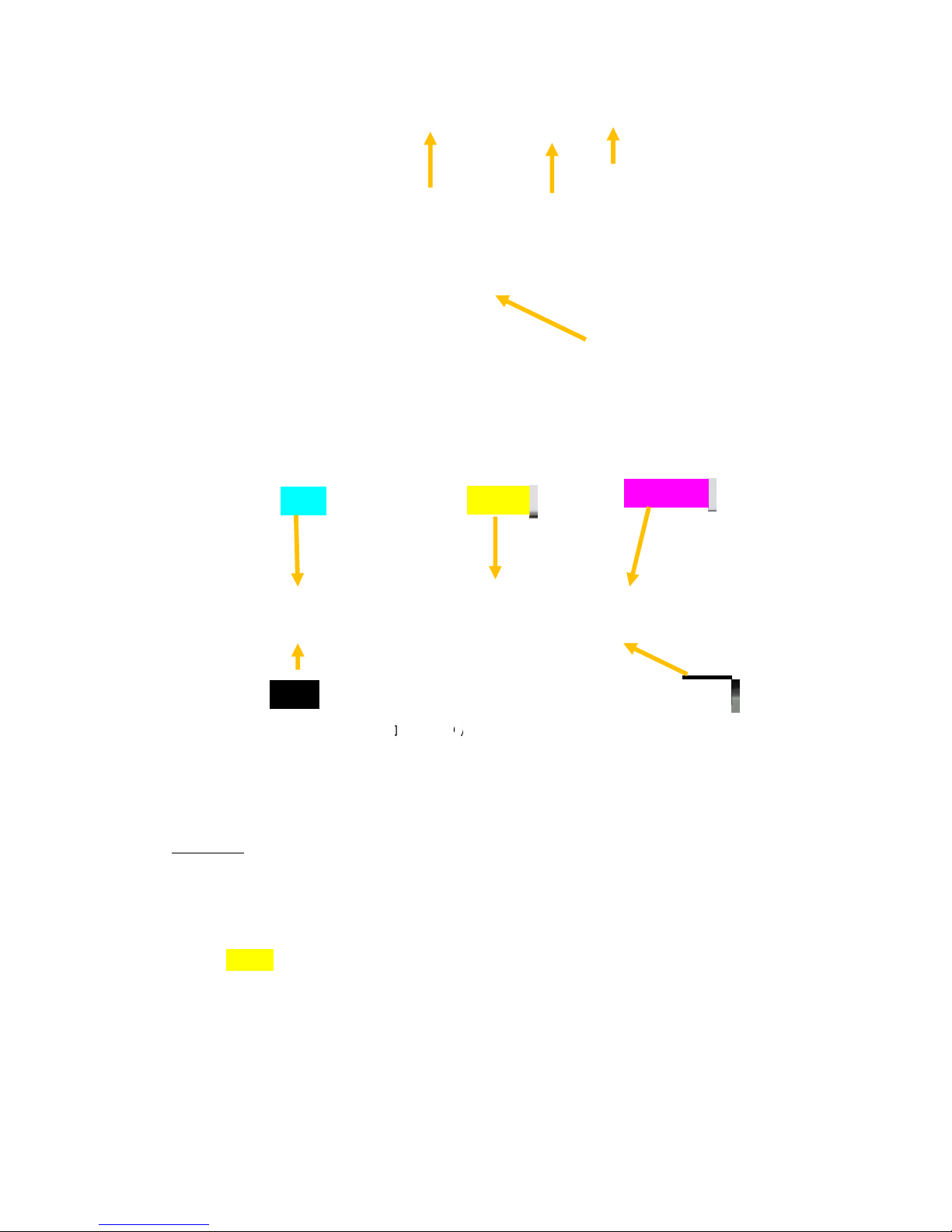
, inserted in the top left slot.
To make sure you have a good contact, remove the ink tank and re - insert twice.
Picture of inserting the ink cartridges
Cyan
Yellow
Magenta
Black
Cyan ) C (
• Black (K) – two cartridges – inserted in the bottom left and bottom right slots.
• Yellow (Y), inserted in the top middle slot.
• Magenta (M), inserted in the top right slot.
WARNING: The ink 29nt he Ink Tanks may be harmful if swallowed. Keep new and used Tanks out
or reach of children. Discard empty tanks immediately.
Black
3.5.3. Installing the Printhead
The printhead is the core of the print engine. As sensitive electromechanical
equipment, it requires careful and special handling to avoid damage and ensure quality
printing. NOTE: The printhead is sensitive to electro-static discharge (ESD). Use ESD
protection when handling the printhead.
Priming the Printhead
Before the printhead can be used, it must be primed. Priming helps purge both the
liquid and air in the ink lines to allow reliable printing. Priming can also help to remove air
-26-
Page 27

CAUTION
bubbles from a previously primed printhead. The priming process is designed to use less
than 5ml of ink.
To prime the printhead manually,
1. Fill the main channels of the printhead.
2. Generate a pressure pulse to push out any bubbles.
3. Clean and dispose of the ink pushed out onto the nozzle plate.
4. Print out color mixed ink.
5. Cap the printhead to prevent dehydration.
DO NOT touch the printhead cartridge ink couplings, nozzle surface or the electrical
contacts when installing the printhead cartridge. Hold the printhead cartridge ONLY
by the handles.
DO NOT unpack the Printhead Cartridge until the Printer is ready for installation.
Once unwrapped, delay in installing the Printhead can compromise print quality due
to dehydration.
DO NOT place an unwrapped Printhead on any surface before installing. Protect the
Printhead from at all times from dust, fibers, dirt and other contaminants.
Installing the Printhead
1. Ensure your printer is switched on and the Power button is lit and steady.
2. Open the cover of your printer to reveal the printhead latch with a screw driver (ONLY at
first use!)
-27-
Page 28

3.
If the printhead latch is not raised, press the Printhead Eject button for three seconds.
This will automatically initiate printhead latch opening. This process may take several
seconds.
4.
Remove the fluidic cap protectors from the two fluidic couplings.
5.
Open the end of the printhead package outer box and slide out the foil bag.
Inspect the integrity of the foil vacuum sealing. The foil bag should be formed tightly to
the contours of the printhead cartridge as shown above. If the foil is loose to any
degree then the seal has been compromised.
If a poor seal is suspected, DO NOT USE the printhead cartridge. Report the issue to
your supplier.
6.
Carefully rip the foil packaging open at the notch. Use scissors if your foil bag does not
have a notch or you are finding it difficult to tear the bag.
7.
Remove the printhead cartridge from the foil bag.
8.
Remove the orange protective plastic cover from the printhead cartridge. Holding the
printhead cartridge by the handle
a.
Release the flaps covering the ink ports (1 and 2).
b.
Release the clip retaining the cover near the center of the printhead cartridge
(3).
c.
Carefully remove the protective cover (4).
-28-
Page 29

9.
Remove the protective strip from the electrical contacts. While holding the printhead
cartridge by the handle with one hand, grasp the pull tab with the other hand and, slowly
and carefully, peel back the plastic strip covering the electrical contacts.
Dispose of the removed strip immediately and do not allow the removed
strip to contact the electrical contacts.
10.
Remove the protective strip from the printhead nozzles. While holding the printhead
cartridge by the handle with one hand, grasp the pull tab with the other hand and slowly
and carefully peel back the plastic strip covering the printhead nozzles.
Maintain an angle of no less than 45° with the printhead surface when pulling on the
strip.
Dispose of the removed strip immediately and do not allow the removed strip to contact
the electrical contacts or the printhead nozzles.
11.
Raise the printhead latch fully until it is upright so you can insert the printhead into the
printer at an angle.
-29-
Page 30

12.
When the printhead cartridge is fully inserted into the printer rotate it to a vertical
position as shown.
13.
Slowly close the printhead latch. The fluidic couplings should advance and seal to the
printhead cartridge.
14.
Close the printhead latch. When the printhead latch is closed, the printer will prime,
clean and cap the printhead automatically. This operation will generally take a minute or
two, and will be obvious from sounds emanating from the printer.
-30-
Page 31

NOTE: The Printer may take up to 12 minutes to set itself up during initial startup. This is
normal. The machine will emit a number of chirps, whirrs and other noises as it circulates ink
and runs systems.
CAUTION
Do not remove the Printhead while fluid is primed in the system!
3.5.4. Switch on the Printer
After the print head and the ink tanks are installed, switch on the printer by switching
on the main switch on the back of the printer. This will power up the print engine and the
controllers.
After few seconds, you will hear the ink pump starting to prime the system, then the
wiper will wipe the print head and starts its first maintenance. During this process the
software is starting to build up the connection to the print engine. This can take up to 10-15
minutes but it is normal so please wait until the GUI for the system indicates that it is in the
ready state.
-31-
Page 32

3.5.5. Media Handling
3.5.1.1. Print Area
Print area can be found on the back of the printer where the operator needs to feed the
materials. Any media type must go through the metal paper guide in order to avoid any
movement during printing.
Picture of Paper guide
Printing Area is dedicated with the green bar. Left edges of Label (Gap) Sensor and
Blackmark (Tickmark) Sensor is shown with the blue marks. During printing the operator has
to align the actual material to these blue marks otherwise the sensors won’t be able to
recognize the media and the printer could run into an error.
Picture of Printing Area
3.5.1.2. Load Media
Take the paper from the roll and see
across under the unwinder’s roller. Don’t
forget to do this because this will strain
the label media during printing.
Drag the papar towards and see across
the roller of the paper guide under the
antistatic brushes.
Feed the paper in the printer till you feel some
resistance.
-32-
Page 33

3.6. Connect the printer to a computer
3.6.1. Direct connection to a personal computer
The printer connect to directly via USB AB cable and a TCP/IP cable. For the driver
installation advice to use the USB AB cable, or install that in offline mode and after the
installtion seletc the correct port for the USB usage.
-33-
Page 34

3.7. Installing the Printer Driver
Your printer can be installed:
A) online via Network
B) via direct USB connection
The preferred installation is over Network, since USB installation process may conflict with
previously installed USB printer software.
A) Installing Printer online via Network Setup Steps:
Make sure your printer is turned on and online
Your printer is connected to your network via LAN cable
Your PC is connected to the same network (LAN or WIFI)
1. On the user PC or laptop, open folder that contains the printer driver software ’R13 driver’
and run WinSetup.exe:
2. As the installer starts, Windows will prompt for permission. Click ’Yes’:
During setup the software may ask for 'Run firmware update'. In such case select 'No'.
-34-
Page 35

3. The setup console will start:
4. Click ’Install printer software’ and accept the terms in the license agreement, then click
’Next’.
-35-
Page 36

5. When asked, select ‘Configure to print over the Network’
6. The installation will begin and a new window will pop-up with the available printers on the
network.
Select your printer and click Next.
-36-
Page 37

7. When the installation is finished, you can set this printer as default and/or print test page
(not necessary). Click Finish button and exit the installer.
8. Open Windows/Devices and Printers, right click on Vortex Printer Series Driver and select
Printer Properties
-37-
Page 38

9. Select Ports tab from the top and deselect Enable bidirectional printing.
Click Apply and OK.
Printer installation is finished.
-38-
Page 39

B) Installing Printer via direct USB connection.
For this method, make sure:
- Your printer is turned on
- You have connected your PC to the printer with USB AB cable.
1. On the user PC or laptop, open folder that contains the printer driver software ’R13 driver’
and run WinSetup.exe:
2. As the installer starts, Windows will prompt for permission. Click ’Yes’:
During setup the software may ask for 'Run firmware update'. In such case select 'No'.
-39-
Page 40

3. The setup console will start:
4. Click ’Install printer software’ and accept the terms in the license agreement, then click
’Next’.
-40-
Page 41

5. When asked, select ‘Configure to print using USB'.
6. When the installation is finished, you can set this printer as default and/or print test page
(not necessary). Click Finish button and exit the installer.
Installation is finished.
-41-
Page 42

Field Values
Default
Letter 8 ½ x 11 in
4 x 10 in
3.7.1. Driver Specifications – Printer Preferences
3.7.1.0. General Tab
Orientation: Portrait(default), Landscape, Rotate 180° and Mirrored
Copies:
Lets you choose the number of copies to be printed.
If choose the reverse order then the jobs starts
6IPS is the Best quality mode with 1600*1600 dpi.
Acces your costum print settings for various jobs
that you uploaded through the „Media Profile
Media type and media size are defined by the Vortex
851R Series Driver and included during installation.
printing after the last page is arrived.
PrintSpeed:
12IPS is the normal with 1600*800 dpi.
My Print settings:
Upload+ int he Toolbox-
Media Type
Media Size
Print Speed (and
Quality)
Color Section
My Print Settings
•
• SpeedJet Glossy Label
• SpeedJet Matte Label
• SpeedJet Standard Label
• SpeedJet Vellum
•
• Legal 8 ½ x 14 in
• Statement 5 ½ x 8 ½ in
• Executive 7 ¼ x 10 ½ in
• A4 210 x 297 mm
• A5 148 x 210 mm
• A6 105 x 148 mm
• 4 x 6 in
• 5 x 7 in
• 5 x 8 in
• 12 IPS
• 6IPS
• Color
• Composite
• Black only
Defaults
•
4 x 11 in
•
4 x 12 in
•
8 x 10 in
Env. Monarch 3 7/8 x 7 ½ in
•
Env. Com 10 4 1/8 x 9 ½ in
•
Env. DL 110 x 220 mm
Hagaki 100 x 148 mm
100 x 150 mm
1 x 1 in
-42-
Page 43

Field
Values
3.7.1.1.Layout Tab
R
esizing –
Lets you specify the
Original Size or
Custom Resize: lets you resize the
original as a % of normal size. The printer will
print the document in the size you selected
regardless of the size of the paper selected.
Print on: lets you specify the particular
size of paper that you want to print on
regardless of the size of the original
document. Checking “Scale to Fit”
automatically resizes the document to fit on
the new page size.
Multipage per N-UP
If would like to print more pages on the same
sheet
My Print Settings: Access your custom print settings for various jobs that you uploaded through
the “Media Profile Upload” in the Toolbox.
Multi-Page (N-Up)
Arrange Pages
My Print Settings
Pages per Sheet: 1,2,4,9,16
• Right, then down
• Down, then right
• Left, then down
• Down then left
Defaults
-43-
Page 44

Field
Values
3.7.1.2.Media Tab
P
rinting Adjustments: Allows you to make
minor positioning changes to the print area
in relation to the media if needed.
NOTE: Only works on jobs using less than
the full print area (less than 8.5" wide).
Media Layout:
possible to set what kind of print jobs will
arrived.
Inter-Label Gap: the media has labels form
Blackmark: the media has blacmark ont he
DOWNSIDE
CUTSheet: cut after the medium size
Continous: in this mode the machine will
print fluently
Use printer setting: the engine has some
setting what can check with the nvm_getset
command. For more information about under
the engine documentation.
My Print Settings: Access your custom print settings for various jobs that you uploaded through
the “Media Profile Upload” in the Toolbox.
Position Adjusment
(offset units)
Media Layout
Page Cutting
My Print Settings
• Horizontal Offset
• Vertical Offset
• Inches
• Millimeters
• Pixels
• Inter-Label Gap
• Black Mark
• Cut Sheet
• Continuous
• Use Printer Setting
• Job Cut (cut at end of job
• Sheet per cut (number of pages before
cutting)
• Use Printer Settings
Defaults
-44-
Page 45

3.7.1.3.Import/Export
W
hen updating to new Memjet driver,
the Import/Export tab is used to save
previously adjusted media sizes and My
Print Settings.
You can also use this function to copy
printer and media settings from one PC
to another.
When exporting these settings, an .ini
file will be generated, which can be
copied onto another computer,- where
the driver is installed as well - and can
be imorted simply.
3.7.1.4. Services
When printer is online, Service menu can be used to carry out manual (not
automated/programmed) maintenance by simply clicking on CLEAN PRINTHEADS button.
PRINTING DEMO PAGE will print Windows demo page.
Make sure you have wide enough – 210mm – continous media fed into the printer prior using this
function)
PRINT CONFIGURATION PAGE will print printer confguration page (IP address etc.)
Make sure you have wide enough – 210mm – continous media fed into the printer prior using this
function.
-45-
Page 46

3.8. Label printing, generating print jobs.
For printing labels the operator has two options:
*Print label from a labelling/graphical or other software
*Print labels from print jobs.
3.8.1. Printing labels from softwares
Printing labels from any kind of software is quite easy. The operator just needs to set all
prefrences within the Vortex 851R Series Driver (paper size, printing speed, number of copies,
etc.)
3.8.2. Printing labels from print jobs.
To help the whole process it is recommended to install the driver on the personal
computer then change the following:
1. Go to Start/Devices and Printer
2. Right click on Vortex 851R Series
3. Go to Printer Configuration
4. Go to Ports tab
5. Change port from TCP/IP to FILE (or Print to File)
Print jobs are pre-defined printjobs which could be usable in the future. The Vortex
851R printer is only working with .PRN files which can be generated from the driver of the
printer.
-46-
Page 47

3.9.0.Printers Buttons
Power button /green LED/
When push the power button, the engine will start and start to priming or will do a little
maintance. At first start should to wait lot time (10-15mins) because the ink delivery system is
empty. Sometimes it takes more than ten minutes. But if the system primed after this time is
shorter.
The green LED always should to light when the machine is ON.
Cancel button /red LED/
This button can cancel the job under the printing. The LED is working only if the button
pressed.
Feed button /yellow LED/
Before printing should to feed the media into the machine. Advice to place the the media to
the left side of the machine because the print engine has the gap and balcmark sensors also
there.
Feed/Unfeed Cancel Feed/Power
-47-
Page 48

3.9.1. Buttons and Led signals
The first button from the left is the Power button, with an integrated Green led. The second button is
the Cancel / Clear Error with a Red led and the last one is the Feed/Unfeed with a Yellow led. The power
button only sorts two GPIO pins so it does not require any kind of software for its operation,
consequently it can be used to power on the engine during the manufacturing process even if there is no
firmware on the machine. The other buttons need the custom firmware components added by the
“V851R_CustomFW.tcl” to be running.
The integrated leds in the buttons are used to give further information about the printer’s current
state, these are listed in the Led Table below:
Led Table:
Green Led: Power Status
• Led On: Engine ON
• Led OFF: Engine OFF
Red Led: Cancel Job / Clear Error
• Led Off: Normal operation-> Button press will Cancel current job
• Led On: Error detected -> Button press will start the Clear Error procedure, further error info
can be denoted by the yellow led’s status described below
• Led Blinking: Doing work (cancelling or clearing error)
Yellow Led: Feed / Unfeed
• Button press will initiate Feed or Unfeed process depending on the current paper status of
the printer.
• Led Blinking : Doing work (feeding on unfeeding)
• Led On + Red Led On: Engine in Paperpath related error state, denotes Paperjam in 95% of
the time
• Led Blinking + Red Led On: Engine in Paperpath_end_of_roll error state, so there is no
paper in the printer or it is unable to detect it
-48-
Page 49

4. Toolbox
On the welcome screen you can select your language and on the left side you will find the
status panel of the engine. If the engine is ONLINE it is ready to print.
4.1.User Interface
-49-
Page 50

Provides access to the Printer User Control screen. From this screen you can Clear Errors,
Cancel a Job, Reset the Job Counter and Reset the Page Counter. You can also perform some
maintenance and operating tasks such as:
Clear Error: If the engine is in error status, it is possible to delete with this button. There are some
fatal states that are unable to delete.
Cancel job: delete the actual jobs. For example, if the machine is in error state and won’t delete
the jobs, after cancel job it will print out the missed jobs again.
Reset job counter: this will reset the job counter
Reset Page Counter: this will reset the page cuonter
Wipe Printhead: this is a cleaning service issue. It will carry out a light cleaning on the printhead.
Circulate Ink: Purges air from the pipes and primes the system after replacing the Ink Tanks or
Printhead Cartridge.
Release Printhead: Performs the same task as the Cover Release Button on the Printer. Pumps the
ink back into the Ink Tanks and opens the Printhead Cover to remove/install the Printhead.
System Deprime: Pumps the ink back into the Ink Tanks prior to replacing the Printhead or
transporting the Printer.
Eject Maintanence Module: this will eject the service station. If you would like to remove it then
use this at first. If not possible to use this button still can remove it manually.
Install Maintane Module: this will call home the service station.
Wiper Inspection: sets the service station in wiper state, so the wiper roller faces upward and can
be inspected.
Wiper Preemtive Maintenance:
from the excessive dehydration in the system.
This algorithm is user-initiated only. It is recommended that it be run once a week, as well as after
extended durations of printer idle time.
Shutdown: Turns the Printer off from your computer.
Pinch Media: this will feed the media.
Retract media: this will unfeed the media
Request Pause: send pause command
Clear Pause: clear pause state
KWS setting: 0, default(3), 7- IMPORTANT! if you change the default settings the printhead will
loose its warranty! If Keep Wet Spitting function isn’t working then the printhead nozzles have
bigger chance of drying out what will make printing mistakes. Lines. This function is a basic
defence of the printhead.
Non Printing Mode: In this mode the printer can calculate inkusage from the job.
Shutdown the Printer: this will shut the engine down. After this the printer itself also needs to be
switched off.
It enables users to re-moisturize the wiper module with ink to recover
4.2.Diagnostics
From this screen you can see the current status of your Printer. You can also:
Print Sample Page – Prints type and color bands to check print quality.
Print Configuration Page – Shows the current configuration of the Printer including Firmware
Version, Network Connection, Printer Serial Number and more.
Print Diagnostic Page – Shows basic printer information, memory, Network Settings, Event Log
and RAM partitions.
Print Demo Page – Prints Memjet Demo Page
-50-
Page 51

Print Color Bars – Prints 7 color bar page to check color quality.
Print Ink Channels – Prints 5 color bar page (YBCBM) to check whether all color channels are
working properly.
MAKE SURE YOUR PRINTER IS SET TO CONTIOUS MODE AND YOU ARE USING CONTINOUS
MEDIA WHEN YOU ARE PRINTING THESE TEST/SAMPLE PAGES.
-51-
Page 52

4.3.Ink Usage
Allows you to monitor the estimated amount of ink left in each of the five Ink Tanks. You can
monitor inkusage and consumption and schedule Tank changes (saving down-time during a print
run.)
NOTE – Ink Usage only works when you start with a new Tank and leave it in the Printer
Please note that ink usage/job history will be lost after turning the printer down.
-52-
Page 53

4.4.Network configuration
On this page you will see the actual engine network configurations. The network settings
page provides information about the network connectivity, Printer name, Domain name, and IP
configuration settings.
dhcp:-if its on then the machine will get an ip address from the router. This is the basic
setting also.
Manually IP settings: turn off the dhcp and autoip and after type the chosen IP into the
IPaddress line and press SUBMIT.
-53-
Page 54

4.5.Service Menus
For authorized peronnel only. Provides acces to more advanced printer control and
maintenance menus.
Under this menu you can find many basic engine settings. Very easy to uncalibrate the engine,
this is the reason of the password protection.
Here possible change TOF,BOF, Cut, Gap, r2r distances, Tof2Tof settings. The driver also can
handle the most of these parameters.
-54-
Page 55

5. Maintenance Guide
5.1. Maintenance Overview
To ensure reliable operation and high print quality while using the product, the regular
inspection and maintenance steps are required to be performed. These include mechanical
subsystems checks, occasional cleanings, consumables changing and print head cleaning.
Cleaning
The most essential maintenance operation is automatic – cleaning the print head and
preventing it from dehydration. The print engine performs various maintenance operations
before and after print jobs and in the background. Normally manual print head cleaning is
not required.
Regular checks
t regular intervals (say at the beginning of a shift or day) inspect that the maintenance
A
station is in cap position, the cutter is not obstructed, the paper path is clean (there are no
paper clippings present), sensors are not covered. Check that wires are not loose, there is
no ink leaking.
If the operator detects print quality problems, check the troubleshooting part for steps to
perform in order to solve the issues.
Consumable change
The main consumables in the printer are the ink and the print head. The most frequent user
intervention during the life time of the printer is the ink cartridge and print head change.
When the printer is running out of a particular ink, the Toolbox will display a message
on the screen specifying which tank is out of ink. Remove the empty tank and insert a new
one and the printer will operate again as before.
NOTE: The printer is working only with all cartridges installed!
5.2. Standard Maintenance
General and periodic maintenance procedures are needed to keep the Print Engine in
good condition. In anticipation of industrial applications, an extensive list of service parts are
available for the printer. Please contact you Reseller for futher details.
High volume usage and specific use cases/configurations may require more frequent
maintenance.
NOTE: Repair and replacement tasks, are referred to qualified technicians! For some
maintenance tasks it is better to remove the engine from the printer!
Use the table below to determine which maintenance task (inspection, cleaning,
lubrication, or replacement, etc.) to perform at a given time period or usage interval.
The following tasks are to be performed by the operator only with very basic supplies, no
special tools are needed.
-55-
Page 56

General Maintenance
Tasks
Daily
Bi-weekly
Interval
Monthly
Anually
As Needed
Printhead (manual wipe)
PPCA Contact Cleaning
IDS Fluidic Couplings
Aerosol & Debris
Removal
Optical Sensors – Paper
Path
Wiper Inspection
Wiper Cleaning
Waste Ink Absorber
Ink Tubing
Lift Motor Gear
Grit Rollers – Paper Path
Moving Parts – Motor
Test
Maintenance Module
Ink Tank Latches
Cutter
Clean
Clean
Clean
Inspect
Clean
Clean
Inspect
Clean
Inspect
Inspect
Inspect
Inspect
Clean
Clean
Inspect
Clean
Inspect
Inspect
Inspect
Clean
Test
Clean
Inspect
Inspect
Wipe
Every PH
Removal
Every PH
Removal
Clean
Replace
In order to avoid personal injury, always use appropriate personal protection when
performing maintenance tasks
• Clothing protection
• Powder-free nitrile gloves
• Lint-free cloth wipes – It is critical that the wipes used be soft to avoid scratching the
prtinhead, and lint-free to avoid contaminating the printhead.
• De-ionized (DI)/Distilled water (electronics grade) – Use only deionized or distilled water
for cleaning the unit. Take care to avoid contaminating the printhead with cleaners,
lubricants, or other chemicals.
WARNING! – Always power down the Print Engine before investigating any cable
connections! The printer runs off a 24-volt DC supply. Although this is considered low
voltage, the current is sufficient enough to cause injuries.
-56-
Page 57

5.2.1. Daily Maintenance Tasks
Aerosol and debris removal
Ink may transfer from printer components into media path. Remove excess ink and debris
daily to ensure optimal printing.
NOTE: If the operator finds paper debris on a starwheel, check to see whether or not it
is aligned with the edge of the media. If so, you may need to adjust the paper guide and
margin so that the starwheel no longer rubs the edge of the paper.
1. Perform this procedure with the printer powered on, so the platen is raised.
2. Pinch the clamshell latches to release, as shown on the pictures. Open the clamshell
and allow the upper portion to rest on the hard stops.
Picture of the clamshell opening procedure
Picture of the opened Clamshell
3. Dampen a lint-free cloth with distilled water.
4. Wipe the system components and paper path surfaces (uppen and lower), with a
clean, damp lint-free cloth, to remove ink overspray (aerosol) and debris.
-57-
Page 58

Platen
NOTE: Do not wipe the starwheels as they may release and fall out. Do not clean the
printhead nozzle plate at this time; it will be cleaned during another task.
5. Use a clean, dry lint-free cloth dry the inside of the unit. Avoid the grit rollers since
they can snag on the cloth and create debris.
Grit
Rollers
Housing
Picture of the Wipe Lower Surfaces
-58-
Page 59

Aerosol
Starwheels
Pinch Rollers
Picture of removing Aerosol from Housing surface
Picture of the Wipe Upper Surfaces
6. Fold the cloth between wipes to ensure a clean, uncontaminated surface is used
each time.
7. Use a vacuum cleaner if necessary to remove debris inside and outside surfaces of
the clamshell.
5.2.2. Bi-Weekly Maintenance Tasks
Aerosol and debris removal
-59-
Page 60

• Paper path optical sensor cleaning
• Wiper inspection
Aerosol and debris removal – see at daily maintenanc
Optical Sensor Cleaning
Clean the four optical sensors in the paper path every two weeks.
1. Pinch the clamshell latch to release and open the clamshell.
e tasks
Picture of Paper Path Optical Sensor Locations -
Top
-60-
Page 61

Picture of Paper Path Optical Sensor Locations -
Bottom
2. Moisten a foam swab with distilled water.
3. Place the damp swab on each sensor and twist back and forth to clean the
surface. Use a new, moist swab on each sensor.
-61-
Page 62

4. Repeat cleaning and drying process for all four sensors.
Wiper Inspection
1
. Pinch the clamshell latches to release and opend the clamshell.
NOTE: The wiper is automatically in the up position when the clamshell is open.
2. Go to Toolbox and click on ‘Eject Sevice Station’ button.
3. Inspect the wiper to ensure that it is spins freely with no excessive noise
4. Check the surface of the microfiber roller (MFR) for any irregularities (bumps, divots,
etc.) or delamination (peeling of the wiper surface at the seam). Iff irregularities are
seen, escalate to a technician for replacement.
5. Use tweezers to remove any large clumps of debris.
5.2.3. Monthly Maintenance Tastks
• Aerosol and debris removal
• Paper path optical sensor cleaning
• Wiper inspection
• Waste ink absorber inspection
• Ink tubing inspection
• Lift motor gear inspection
• Paper path grit roller inpection
Aerosol and debris removal; Paper path optical sensor cleaning; Wiper inspection – see at biweekly maintenance tasks.
Waste ink absorber inpection
Waste ink absorber must be inspected every month. The waste ink absorber was designed
to last the life of the printer under normal printing conditions.
1. Release the waste ink tray latches at the front of the unit and slide the tray out.
-62-
Page 63

Waste Ink Tray Latches
2. Even the absorber is completely darkened with waste ink, with no white showing, it may
still be able to hold additional ink due to evaporation. The capacity of the waste ink
absorber is 1.6L. Visually inspect the waste ink absorber and tray to see if there is ink
leaking out of the tray. If yes, replace the absorber with a new one.
3
. Slide the waste ink tray back into the frame until it clicks.
Ink Tubing Inspection
The following ink tubing and connections, visible to the operator, must be inspected every
month:
• Fluidic coupling (aka Revolver Caps)
• Buffer box
• Pinch valve
• Peristaltic (ink) pump
Refer to the following pictures to identify the specific harwares.
1. Remove any housing or covers positioned around the ink tubing.
NOTE: The clamshell should be closed during this procedure.
-63-
Page 64

Ink Tubing
Pinch Valve and
Pump Motor
Vents (x5)
Buffer Box
Picture of Rear Ink Tubing Detail
Peristaltic (ink) Pump
Tubing into Fluidic
Couplings
Peristaltic
Pump
Pinch Valve and
Vents (x5)
Picture of Ink Tubing Connections
Use a finger to gently pry both fluicid coupling covers off in order to inspect the ink tube
connections underneath.
-64-
Page 65

2. Visually inspect each tubing connection point for leaks. If leaks are found, escalate to a
technician for troubleshooting.
3. Follow the exposed length of each tube and visually inspect each ink tube for inks or
pinches in the tubing. Undo the irregularity to allow ink to flow freely. Escalate to a
technician if leaks result.
4. Re-install the fluidic coupling covers.
5. Re-install any housing removed to access this area.
Picture of Remove Fluidic Coupling Covers
-65-
Page 66
Lifter Motor – Gear Inspection and Encoder Cleaning
T
he lift motor gear, on the right side of the unit, must be inspected every month.
1. Inspect the lift motor gear for general wear (worn teeth, debris, etc.). Remove any
debris found. If excessive wear is observed, escalate to a technician for repair.
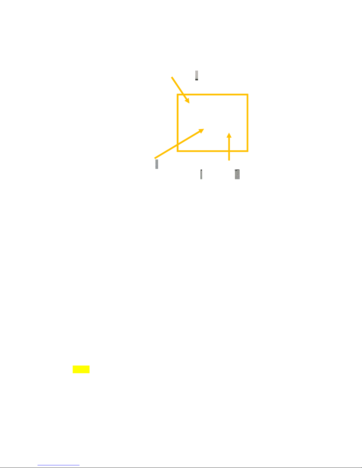
Picture of the Lift Motor
2. Use a lint-free wipe, damped with DI water, to very gently clean exposed encoders.Gently
rotate the encoder after each wipe to ensure cleaning of the entire surface.
NOTE: On some printer there is a cover on the lift motor encoder that protects it from aerosol and
debris. No cleaninig is required on these units.
-66-
Page 67

Picture of removing the Lift Motor Encoder Cover
Picture of cleaning the Lift Motor Encoder
aper Path Grit Roller Inspection
P
The three paper path grit rollers must be inspected every month.
Grit
Rollers
Picture of Grit Rollers
-67-
Page 68

1. Inspect the print rollers for ink residue and debris. If none is found, proceed to the
next PM task. If residue is seen, perform the following steps to remove it.
Picture of Grit Rollers with residue
2. Lightly moisten a toothbrush with a small amount of DI water.
3. Gently scrub the grit rollers to remove any ink or paper dust. Manually rotate the
rollers to ensure that they are completely clean.
4. Use a shop towel to dab the rollers and remove any excess moisture. Do not rub the
towel back-and-forth or fibers will be left on the grit rollers.
5.2.4. Annual Maintenance Tasks
Perform the following maintenance procedures once a year:
▪ Aerosol and debris removal
▪ Paper path optical sensor cleaning
▪ Wiper cleaning
▪ Waste ink absorber inspection
▪ Ink tubing inspection
▪ Lift motor gear inspection
▪ Paper path grit roller inspection
▪ Moving parts (motor test)
▪ Maintenance Module sled assembly cleaning
▪ Paper dust removal
▪ Ink tank latch/ink bay inspection
▪ Cutter inspection
Aerosol and debris removal; Paper path optical sensor cleaning; Wiper cleaning; Waste ink
absorber inspection; Ink tubing inspection; Lift motor gear inspection; Paper path grit roller
inspection – see at monthly maintenance tasks.
Moving Parts Motor Test
. Activate the media path, cutter, pump, pinch valves, and maintenance module and
1
listen for any noises not present when the printer was new.
2. Inspect the motion of the media path and the maintenance module to ensure the
motion looks smooth and free.
-68-
Page 69

Maintenance Module Cleanining
C
lean the Maintenance Module (aka Service Station) every year.
1. Lay absorbent disposable towels under the base of the printer.
Picture of layed towels
NOTE: it recommended to do a System Deprime before ejecting the Maintenance Module.
Also it is better to remove the printhead and cap itt o avoid contamination and adequate
moisture.
2. Int he Toolbox push ’Eject Service Station’ button to send the Maintenance Module to the
eject position.
The maintenance module moves forward for easy access.
3. Prepare a large absorbent towel to catch any ink which might leak from the
maintenance module or the wick to the waste ink reservoir. Make sure to fold the
towel over 2 or 3 times so that it can absorb lots of ink. Be prepared to cover the
bottom of the maintenance module with the towel as you pull it out.
Maintenance Module in Forward Position
-69-
Page 70

Manually rotate the maintenance module positioning gear until the module disengages from the
drive gear and gently pull the module forward until you can disconnect it from the translation
motor.
4. Disconnect the ribbon cable connector for the wiper motor to free the MM.
Picture of disconnecting MM from Wiper Motor
5. Use a lint-free cloth, moistened with DI water, to gently remove any ink residue or
debris from the Maintenance Module. Once the lint-free cloth is soiled, use a new
cloth.
Picture of Ink Residue removal from the Maintenance Module
6. Inspect both wicks (printing platen and cap) for warping, plugged up sections, or to
see if it is falling out. If fouled, escalate to a technician for replacement with new
wick(s).
-70-
Page 71

7.
Inspect the cap for ink contamination and cracking or permanent deformation of the
cap. If permanently damaged, escalate to a technician for replacement.
Picture of wiping the Cap Seal wuth damp lint-free cloth
8.
Inspect the wiper module components for damage or permanent deformation. If
permanently damaged, escalate to a technician for replacement.
9.
Remove the paper dust from underneath the maintenance module, during the annual
cleaning. Use a vacuum cleaner for the interior of the unit, if necesarry.
Picture of using a Vacuum cleaner to remove debris from under the MM
Wiper cleaning
Wiper cleaning usually means that the oparator has to change the microfiber roller as it
comes to the end of its lifetime. The operator can easily recognize this stage. First of all the
shape of the roller turns from rounded to ellipse. Secondly this chage within the shape will
cause significant noises during maintenance.
NOTE: Lifetime of the wiper roller depends on the usage, but should be change at least
twice a year.
1.
Disconnect the wiper motor connector PCB from the mounting clip.
-71-
Page 72

Picture of disconnecting wiper PCB from Wiper Housing
2.
Disconnect the wiper PCB from the ribbon cable, as shown in the figure below.
Picture of disconnecting Wiper PCD from ribbon cable
3.
Route the ribbon cable through the housing to free the wiper, as show non the next
pictures.
4.
Flip up the retention tab at each end of the wiper assembly to free the microfiber
roller.
Picture of routing ribbon cable through housing
-72-
Page 73

Retention
tab
-73-
Page 74

5.
Remove the MFR to access the transfer roller (TR) that is installed below the MFR in
the wiper module assembly.
Picture of Transfer Roller (TR)
6.
Visually inspect the transfer roller (TR) for unusual ink accumulation. The transfer
roller is stainless steel. Ink may accumulate in scratches on the roller. Wash the
roller with damp lint-free cloth if necesarry.
7.
Re-assemble the wiper module.
8.
In Toolbox press’Home Service Station’ button to re-install the MM into the print
engine.
Ink Tank Latches Inspection
1.
Release the three ink tank latches.
Carefully slide all five ink tanks, one at a time, out of the unit.
Picture of released ink tank latches
Picture of removed Ink Tanks
-74-
Page 75

Picture of opened and closed Int Tank La
tch
2.
Verify that Toolbox reflects the tank removal.
3.
Align each ink tank with the rails on the printer and insert. Repeat until all five ink tanks
are re-installed.
Picture of re-installing Ink Tanks
4.
Re-fasten each ink tank latch to ensure it moves properly and engages fully. If not,
escalate to a technician for replacement.
-75-
Page 76

5.2.4.1.Cutter Inspection and Cleaning
WARNING! – To avoid personal injury, power off the printer before performing this task!
1.
Fold a damp lint-free cloth and insert it into the groove beneath the cutter
General maintenance
Pictures of cleaning the Cutter
2.
Wipe back and forth to remove aerosol and debris
3.
Remove any media debris from the cutter with tweezers.
-76-
Page 77

2.
Locate the printhead nozzle strip.
Picture of Printhead Nozzle Plate
5.2.5. As Needed Maintenance Tasks
The following general maintenance tasks should be performed on an as needed basis,
based upon inspection during every day use and/or when performing other tasks.
The printhead cartridge should be manually wiped after the following occurrences:
• after paper jams
• before re-installing an used printhead cartridge into the print engine
• if print quality is showing signs of contamination
• if automated maintenance algorithms prove ineffective for nozzle recovery. There
are two methods for cleaning the print head cartridge; one with it installed and one with it
removed from the unit. Both methods are listed below. When removing and reinstalling an
used printhead or when replacing a printhead, use the second method.
Printhead Cartridge Cleaning (Manual Wipe While Inst
Perform the following steps to ensure proper printhead cleaning without removing it:
1. Pinch the clamshell latches to release. Open the clamshell and allow the upper
portion to rest on the hard stops.
alled)
Picture of opened Clamshell
-77-
Page 78

3.
Dampen a lint-free cloth with distilled water
4.
Gently wipe the print nozzle plate from one end to the other
Picture of wiping the nozzles
5.
Fold the cloth and clean the nozzle plate again to remove remaining debris.
Pictures of soiled lint-free cloth
Close the clamshell.
Printhead Cartridge Cleaning (Remove Cartridge)
Preparation
1.
Lightly dampen a lint-free cloth with DI water.
2.
Set the wipe on a clean surface.
3.
Lightly moisten the cloth strip in a PH shipping cap with a small amount of DI water
and set aside.
-78-
Page 79

Picture of moisten PH Cap
Perform the following steps to ensure proper printhead cartridge cleaning:
4.
Open the toolboox and press system deprime. This command will de-prime
the system. During de-priming, the printhead latch will release. Listen for the latch to
click and observe that it is “popped up” when release is successful.
Picture of released PH Latch
-79-
Page 80

Latch popped up
Ink backs out of tubing
during de - prime
5.
Open the latch.
Picture of released Latch and empty ink tubes
-80-
Page 81

Picture of tilting PH towards rear of the unit
6.
Tilt the printhead cartridge towards the rear of the unit until it clicks.
7.
Slide the printhead cartridge out of the print engine.
Picture of sliding the PH out of the unit
8.
Gently wipe the printhead from one end to the other, with a lint-free cloth moistened
with DI water, and then cap the printhead to keep it moist while performing other
tasks.
Picture of wiping PH nozzle strip
-81-
Page 82

Picture of PPCA Contacts
PPCA Contacts
Picture of capping the PH
NOTE: Each time the printhead is removed, clean the PPCA contacts and fluidic couplings!
9.
Locate the PPCA contacts.
10.
Use a new, lint-free cloth dampened with DI water to gently wipe up-and-down to
clean the PPCA contacts.
Use only a very gentle up-and-down motion (never side-to-side) because the contact pins
are very easy to bend which can damage the printhead and the printhead circuit board!
CAUTION
-82-
Page 83

Picture of cleaning the PPCA Contacts
11.
Locate the fluidic couplings.
Fluidic Couplings
Picture of Fluidic Coupling Location
12.
Moisten a foam swab with DI water.
Picture of Fluidic Coupling with ink residue
-83-
Page 84

Pictured of moisten swab
13.
Place the foam swab in one of the ink channels on the fluidic coupling and rotate to
clean.
Picture of cleaning the ink channel
14.
Use a new, moist foam swab and repeat the process for each ink channel on both
fluidic couplings until all 10 openings are cleaned.
Picture of soiled swab for one fluidic Coupling (5-channels)
-84-
Page 85

15.
Remove the cap from the printhead
Picture of uncapping the PH
16.
Wipe from one end to the other with the damp lint-free cloth.
Picture of wiping the PH
17.
Align the PH cartridge with the pin on the PPCA board and slide it into the print
engine.
Picture of PH alignment Pin
-85-
PH Alignment
Pin
Page 86

Alignment Pin
PH Groove
Picture of PH alignment pin interface
18.
Tilt the top of the printhead cartridge toward the back of the printer, about 20º.
19.
Gently seat the back of the printhead cartridge into the print engine.
20.
When the back of the printhead is firmly seated, gently rotate the printhead
cartridge into position against the stops on the printhead connector board until it
clicks into place.
If the printhead will not rotate into position, do not force it!
21.
Slowly close the printhead latch. The fluidic couplings will advance and seal to the
printhead cartridge.
22.
Close the printhead latch. When the printhead latch is closed, the printer will prime,
clean and cap the printhead automatically. This operation will generally take a
minute or two, and will be apparent from sounds emanating from the print engine. If
the engine don’t start it automaticaly, then open the toolbox and press thesystem
prime.
23.
When the system is primed, print a test printjob from Toolbox to make sure the
cleaning process was right and the printhead is working properly.
CAUTION
-86-
Page 87

Waste Ink Absorber Replacement
The waste ink absorber was designed to last the life of the printer under normal printing
conditions, taking into account evaporation. Replace the waste ink absorber when ink is
leaking out of the waste ink tray.
1.
Use fingers to squeeze the waste ink tray latches inwards, at the front of the unit, to release
and slide the tray out.
Waste Ink Tray Latches
Waste Ink Tray Latches
Waste Ink Absorber
2.
Use a gloved hand to pull the waste ink absorber out of the waste ink tray and dispose of it
according to local regulations.
3.
Align a new waste ink absorber with the shape of the waste ink tray and push into place
until evenly seated and flush with the tray top edge.
4.
Slide the waste ink tray back into the frame until it clicks.
-87-
Page 88

Motor stalls
• Jammed gear train from
1.
Check through each
Color Mixing
• Wiper roller (microfiber
1.
If wiper roller is
Unable to remove
Latches on the
Contact Customer Service or
6.Troubleshooting
6.1. Maintenance Module (aka Service Station) Troubleshooting
The following table lists some possible problems related to the maintenance module, with
possible causes and solutions.
Problem
Possible Causes
Solution
broken post or improperly
seated gears
• Squeegee (doctor blade)
wedged, not seated
properly
• Debris build-up on blade
and rollers, increasing
friction
• Bad motor
roller (MFR)) is saturated
• Squeegee (doctor blade)
wedged, not
seated properly, or is
bowed
of the possible
causes.
2.
If possible, correct the
situation. For example,
re-seat the gears and
squeegee, clean off
debris from blade and
rollers.
3.
Re-test.
4.
If motor is still stalled,
contact Customer
Service
saturated, replace it.
If squeegee is not
2.
seated properly,
reseat it.
3.
If squeegee is bowed,
contact Customer
Service
maintenance module from the
print engine
maintenance module
were not completely
closed when the MM
was inserted and they
are now hooked on the
bottom of the paper
path
-88-
your Application Engineer
Page 89

Air and air bubbles causing
Appear as missing groups of
Cured by recirculation,
Debris on printhead
Shows up as regularly
Cured by automatic servicing
Ink mixing
Appears as mixed or muddy
Cured by automated serving
6.2. Printhead Troubleshooting
Occasionally, print quality is affected by minor problems that arise with the printhead. The
following table provides a list of common printhead issues, their symptoms, and solutions:
Problem
bloacked nozzles
Electrical failure or poor
electrical connection
Problem Causes
adjacent drops but the shape
is often rounded or irregular
missing
or misdirected nozzles, or as
ink color mixing
colors. Can be caused by ink
flooding, air in the
printhead, or a dirty
printhead
Results in no print or crisp
blocks of missing drops
usually conforming to the
printhead die boundaries
Solution
priming or cycles of
depriming and repriming.
Often the bubbles will go
away with time
or manual wiping
or manual wiping
Cured by reseating the
printhead or replacing the
printhead
6.3. Print quality problems
Print quality problems are detailed in the Troubleshooting Guide.
Please contact Customer Support for further details.
-89-
Page 90

6.4. Vortex 851R Troubleshooting Guide
GENERAL
Documents to read before (available on ftp)
Print engine:
•
OEM Setup and Operations Guide
•
OEM Troubleshooting Guide
•
OEM Service and Repair Guide
•
Technical Specifications
Vortex 851R:
•
Training – software module
•
Troubleshooting Flowchart
•
SSC Release Notes
Checklist before doing any support
•
Firmware is 20140509 version
•
Driver is R13
•
Print engine serial number
•
USB AB cable is attached to print engine
•
TTL cable is attached to print engine
•
Preventive maintenance is done / sensors are clean
•
KWS = default (3)
•
NVM pages_per_cut = -1
•
NVM Mpcarev 5
•
NVM wiper motor E
•
NVM pump motor B
•
.NET 3.5, 4 is installed
-90-
Page 91

Troubleshooting Tools
Serial communication between the NorthStar print engine and the host PC enables
detection and analysis of issues. You will also need the related software for entering
commands, serial logging. More information about it int he next phase.
Serial Communication and Related Tools
The most important troubleshooting tool is serial communication, which requires a special
serial cable and some software on the PC.
Recommend using PuTTY, a free, open source terminal emulator with strong logging capability.
Once serial communication is set up, use serial logging for debugging issues.
Using TCL Commands and TCL Help
any of the resolution actions listed in this document do not describe the exact TCL
M
commands used. It is critical that any user of TCL be familiar with the self-documenting help
feature.
Newer and better TCL commands are often being added and TCL commands can vary from
one version of firmware to another.
Enter the appropriate TCL command to get the latest TCL commands and descriptions
currently on the system.
For example:
For a complete alphabetical list of TCL command with the description (that is, the
“verbose” version), arranged in an 80 character column, enter help
For a description of a specific TCL command, enter help [Exact]2, where <srch> is the keyword.
To read sensor values, use GPIO commands, for example: TCL> help gpio 2
Serial Logging
erial logging records everything the printer does and keeps it archived. Recommend
S
keeping PuTTY running at all times, with the logging feature enabled to create an unlimited
length file, and using some scripts to occasionally copy the file contents to an archive location
and trim the file back to zero size. It is good practice always to keep serial logs for long term
reference.
Use TCL Help to learn about debug levels. Setting a higher debugging level will display
more information. However, setting debugging too high can interfere with printer operations,
since it takes time to write information to the log, so finding a debug level that’s appropriate is
important.
Installing and checking the Custom Firmware routines
The custom Firmware routines used for extending the printers control interface with the
buttons are stored in the Engine’s flash memory and are non-volatile, but firmware burning will
clear the flash, so the custom extensions need to be reapplied after firmware upgrade!
Adding the custom routines is done by uploading the “V851R_CustomFW.tcl” file to the
engine via USB, after there is working R13 Firmware on the engine. “V851R_CustomFW.tcl” can
be send to the engine with the help of the attached “Add Custom FW Routines.bat” batch file. Or
manually from command prompt by typing “usbcmd –i V851R_CustomFW.tcl”. Of course the
correct path need to be set for the usbcmd.exe as well as the .tcl file, and the engine need to be
-91-
Page 92

under power, connected via USB and the firmware in standby mode! As long as the .tcl file the
batch file and the USBcmd.exe are in the same folder there should be no issues with the upload!
After the custom routines are burned to the flash, the engine need to be restarted! The result
can be checked via TTL cable during the power-up sequence the engine will print the following
messages onto the TTL output:
1. Custom Intitialization completed!
2. Starting ErrorCheckDaemon
3. Starting ButtonHandler Deamon
4. Initialization finished!
Their sequence is fixed, but there can be other messages between them, if the TTL
connection is established too late to catch the initialization issuing a “dbg_replay” command will
replay the recent outputs from the engine. Alternatively, sending a “checkCustomDaemons”
command will print the current status of the resident processes to the TTL output. The result of
this command should be “ButtonHandler already running” and "ErrorCheckDaemon already
running", this means that the two resident processes are currently running so the initialization of
the printer was successful.
-92-
Page 93

Dead engine,EWS,Firmware
Dead engine: When is a print engine dead?
After Dediprog re-flash, the putty output is empty or not interpretable, green LED is off.
EWS: How can I reach the print engine information page?
Open the toolbox.
Firmware: How can I burn the firmware?
All firmware has a Readme file. Usually that file has a ddetailed description about the firmware
burning. The firmware burning is working step by step. mech_state of the engine should return
STANDBY before running Step 2 and Step 4!
If the engine is not starting, or the Toolbox cant see
The best for the next parts to use TTL usb cable also!
Engine IP address dropout
How to detect:
net_myIP
Engine MAC address dropout
How to detect:
net_MAC_addr
does not return 010101010101
How to fix:
net_MAC_addr 010101010101
Firmware dropout
How to detect:
After starting the engine PuTTY returns:
ABCDGK012LMNPQRST
BootCode: Ver = 2010-2-23, v.1 program:28, platform:1 Processor speed 650, Memory Size 67108864, ASIC ID 0x1162620
How to fix:
Burn the firmware by running
Step 3; Step 4
OR
Re-flash with DediProg, than adjust NVM getset, IP and MAC address settings.
-93-
Page 94

PRINT ENGINE: ERROR MESSAGES
Crit 63 03-phead offline cancelpage
1. Clean printhead contact sensors.
2. Replace print head
3. Flash Omnipec
4. Replace Omnipec
CARTRIDGE_MISSING_X
•
clean cartridge chip with isopropyl alcohol
•
clean chip readers with isopropyl alcohol
•
run cm_ink
•
replace ink cartridge
DATA_PATH_UNDERRUN
•
clean the encoder wheel
•
reduce image complexity
•
reduce print speed to 6 IPS
•
check for NVIMG corruption update EEPROM with Step 1
•
use Adobe Reader 9 (good) instead of 10 (bad) for printing
-94-
Page 95

Fatal 71 02 offline cancelpage
Dongle
Please ensure:
1. That P2002 on the MPCA has not been lifted from the solder pads on the PCA
2. That there is insulating tape on the dongle covering the solder pads
3. That the wires between the dongle PCA and P2002 are connected to the dongle PCA
and to the connector
Incorrect NVM settings Interruptioin the sensor powe
r
How to detect:
gpio_pin_get SNSR_PWR_B_EN
returns 0
How to fix:
gpio_pin_set SNSR_PWR_B_EN 1 ss_home mech_clear_error
Lift sensor dirty
Clean lift sensor
Service station connection fault
Eject service station, unconnect, connect, home
Clean service station
Replace service station
Service station is in wrong position
How to fix:
maint_enable 0 ss_goto cap
gpio_pin_get SS_LIFT_UP
ss_down gpio_pin_get
SS_LIFT_UP maint_enable 1
Explanation:
The state of the lift sensor can be checked by running the following TCL commands after the
engine is fully booted:
1) maint_enable 0 (disables maintenance to prevent the maintenance state machine from
overriding commands to position the maintenance module)
2) ss_goto cap (moves to the capped position and raises the cap)
3) gpio_pin_get SS_LIFT_UP (should return a 1 indicating that cap is lifted and that the sensor
is reading the correct position. Verify that the cap is lifted to the full height; if not then there
is a problem with the lift mechanism. If the cap is lifted, then there is a problem with the
sensor).
4) ss_down (lowers the cap)
-95-
Page 96

5) gpio_pin_get SS_LIFT_UP (should return a 0 indicating that the cap is down). 6)
maint_enable 1 (re-enable the maintenance state machine).
Service station position unkown
How to detect:
ss_pos
returns unknown unknown
How to fix:
1. Clean service station
2. Replace lifter arm if broken
3. Clean sensor sled
4. Replace sensor sled
Old firmware
Upgrade firmware to at least 20140509, if possible, with DediProg.
Paper sensor connectivity
Follow CF07 of OEM Troubleshooting Guide
Valve is giving a clicking noise
Move the valve to all possible positions by ids_valve:
ids_valve openink ids_valve openair
ids_valve closed
Valve motor problem
Valve motor broken, or blocked by a particle. So engine can’t recognize its position.
Disassemble and check, replace if needed.
Valve position unknown
How to detect:
gpio_pin_get IDS_VALVE_POS1
returns 1
AND
gpio_pin_get IDS_VALVE_POS2
returns 1
How to fix:
This can be due to misalignment of the disk on the valve shaft and may require
replacement of the pinch valve (try manually cycling the valve using tcl commands to openink,
openair, & closed and see if the appropriate position is returned). Before attempting to
change out the valve, de-power the engine, then remove and reinsert all electrical connectors
at the valve. If this fails to correct the problem, then the valve needs to be replaced.
Appendix A - Capturing the sensor/encoder data durin
Memjet
For servo move debounce to work the following settings and their values should be set
(this is the default on power up):
g lifter arm movement for reporting to
-96-
Page 97

TCL> servo_debounce SSLift
15
TCL> vars_getset servo_disable_gpio_debounce
0
--- Instructions for collecting sensor history information ---
0.turn off maintenance:
maint_enable 0
1. add lift sensor to servo history:
servo_sensor SSLift 0 SS_LIFT_UP
2. store lift servo history:
servo_history_store SSLift
3. go to known position and set start servo position to 0:
ss_down; servo_pos SSLift 0
4. reset servo history:
servo_history_reset
5. run lifter servo for ~2 rotations:
servo_move SSLift 50000 150000
6. on PC run this command to download servo history:
usbcmd.exe -c servo_history > sslift.txt
7. go back to known position and turn maintenance back on:
ss_down; maint_enable 1
MAINTENANCE_BUSY
Entry/exit sensors indicate paper inside the engine
How to detect:
gpio_pin_get PZONE_ENTRY_SNSR
returns 1
AND
gpio_pin_get PZONE_EXIT_SNSR
returns 1
How to fix:
•
Check for paper pieces left inside the engine
•
Clean both sensors
NVM dropout
How to detect:
nvm_getset mpcarev
returns 3
nvm_getset wiper_motor
returns none
-97-
Page 98

nvm_getset pump_motor
returns 0
How to fix:
nvm_getset mpcarev 5 nvm_getset
wiper_motor E nvm_getset pump_motor
B shutdown 1
PAPERPATH_CUTTER_ERROR
reset
PAPERPATH_FEED_TIMEOUT
•
clean sensors
•
check paperpath
•
check paper settings & positioning
PAPERPATH_PAPERJAM
•
clean entry/exit sensors
-98-
Page 99

6.5. Print Quality Issues
Print quality issues can be grouped into the following categories, as explained in subsequent
sections. Two-letter abbreviations are used as the prefix for each category, so that they can be
reported to the support team and tracked with metrics for further analysis.
• Color Mixing (CM)
• Streak (SR)
• Dot Misplacement (DP)
• Banding (BD)
• Other print quality General Defects (GE)
Color Mixing (CM)
Color mixing (unwanted intrusion of one or more colors in another color’s area) shows in a
range of defects, as illustrated here and detailed in issues with the CM prefix.
Picture of Color Mixing Samples
-99-
Page 100

Examples for Color Mixing
CM01: Fine Clouds of Ink or Misting
Issue CM01: Fine Clouds of Ink or Misting displays as a fine spray of small ink drops from
the upstream print area that is falling on the downstream print area of the page.
Picture of Color Mixing: Clouds of Ink
Picture of Color Mixing: Fine Misting
-100-
 Loading...