

Page 1
150 Mini Instruction manual
International edition
Rev 1.1 - July 2016
Page 2

2
Thank You!
The team that designed the Vortex Mini would like to thank you for purchasing this product.
Many hours of development, and testing time went into the product, we truly hope that this is reflected in your
experience with the product.
The 150 Mini was designed as an entry-level racer, priced much lower than it’s 250 Pro big brother, but with all of
the features, and twice the smiles.
We would love to hear your feedback on the product, whether good or bad, at feedback@immersionrc.com.
Page 3
3
WARNING
Congratulations on your purchase of one of the hobby’s first ARF pure-bred racing quadcopters. A product
designed by FPV Racers, for FPV Racers.
Do not expect it to fly like a DJI Phantom™ . It does not have a return-to-home feature, no GPS, and it does not
have stabilization features that will allow your little brother to fly (to be honest, we think your little brother might
be faster than you around the back yard…)
Take it easy if you are new to the world of FPV racing, try to avoid slamming the quad into the first wall before you
have mastered slaloming through the trees on the way to the wall.
Acro mode is something that should be learned as soon as possible, flying any other mode is a bit like driving a
Lamborghini around a parking-lot in reverse… not exactly what you bought the Lambo for.
Please carefully read the recommendations in this manual, and the related getting-started guides, as far as
equipment/battery selection, and how to run the Vortex 150 Mini Wizard.
REMOVE PROPS
Mini-quad props can do serious damage when coming in contact with human skin, risk of deep cuts and
lacerations should be avoided at all cost.
So when you are working on a quad with the battery connected, it is highly recommended to REMOVE ALL PROPS,
unless you are just about to fly. Keep in mind that when setting up mini-quads, there is always a remote chance
that a configuration change can spin up motors unexpectedly.
ImmersionRC accepts no responsibility, or liability, for any injury, or damage, to persons or property, caused by the use of
the Vortex.
INSTALL ANTENNA
The Video Transmitter included in the Vortex may be damaged permanently if run without the supplied SpiroNET
Antenna. Please take care to install this antenna before every flight, and when powering up the Vortex for even a
short time period.
ImmersionRC accepts no responsibility for damage caused to the Vortex by operating without a suitable Tx antenna
installed.
Page 4
4
Getting Started for Newcomers to Race Drones
This manual focuses on preparing your 150 Mini for first flight, and how to maintain it in the future. One step that
is highly recommended for newcomers to the world of racing drones is to take the first flight within the safety of a
simulator.
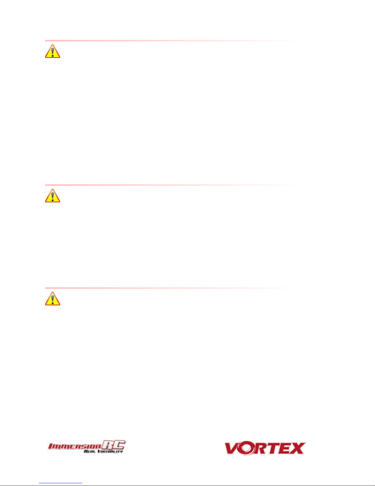
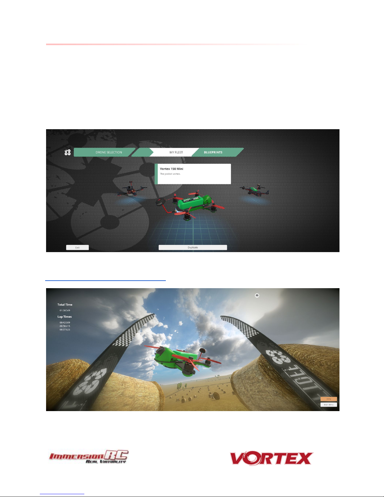
Lugus Studios ‘Liftoff’ simulator contains a full realistic 3d simulation of the Vortex 150 Mini, and is an ideal way to
get the hang of flying a racer without breaking props.
Get the hang of hovering, turning, carving around flags, racing through gates, before charging your first battery.
Liftoff is distributed on the Steam platform, and may be downloaded from here:
http://store.steampowered.com/app/410340/
Page 5
5
Getting Started, ARF Version
The separate Getting Started guide should be used when setting up your Vortex 150 Mini for the first time. It
includes sections on choosing an appropriate battery, and R/C receiver, and also the operation of the setup wizard.
Page 6
6
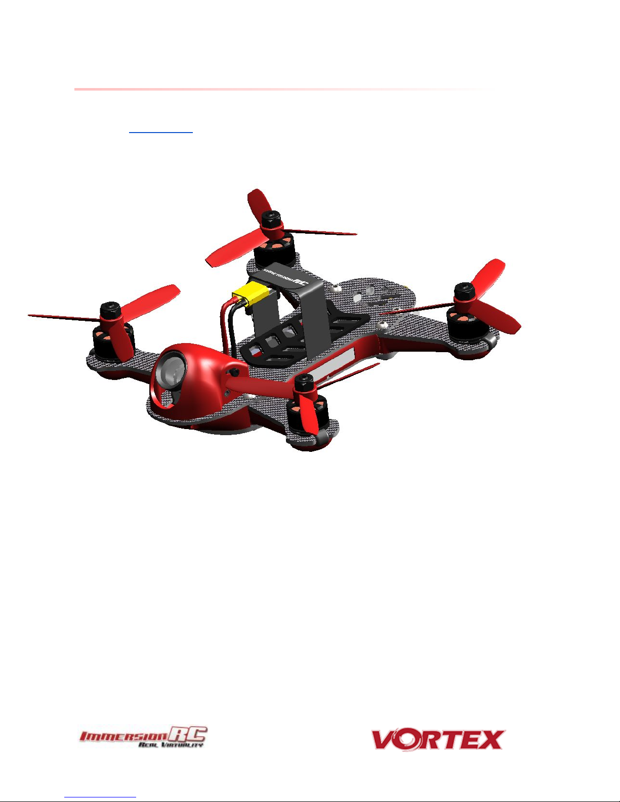
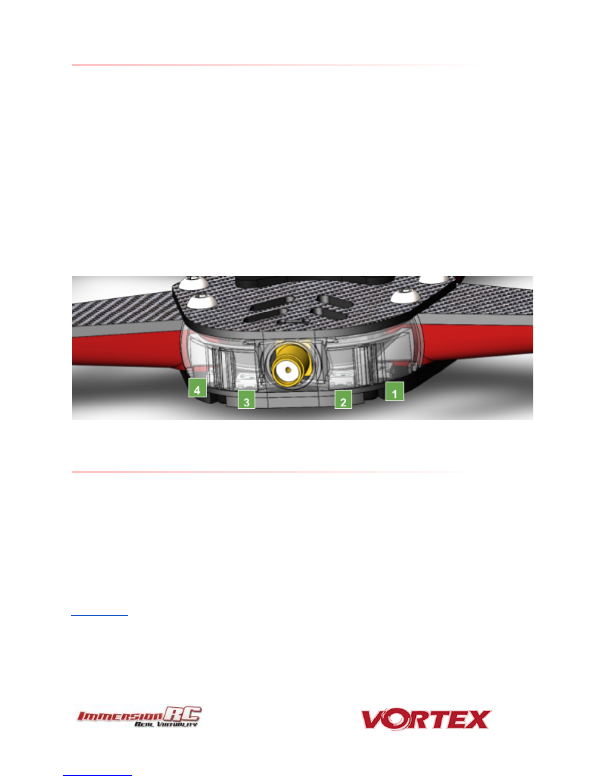
The Anatomy of a Vortex 150 Mini
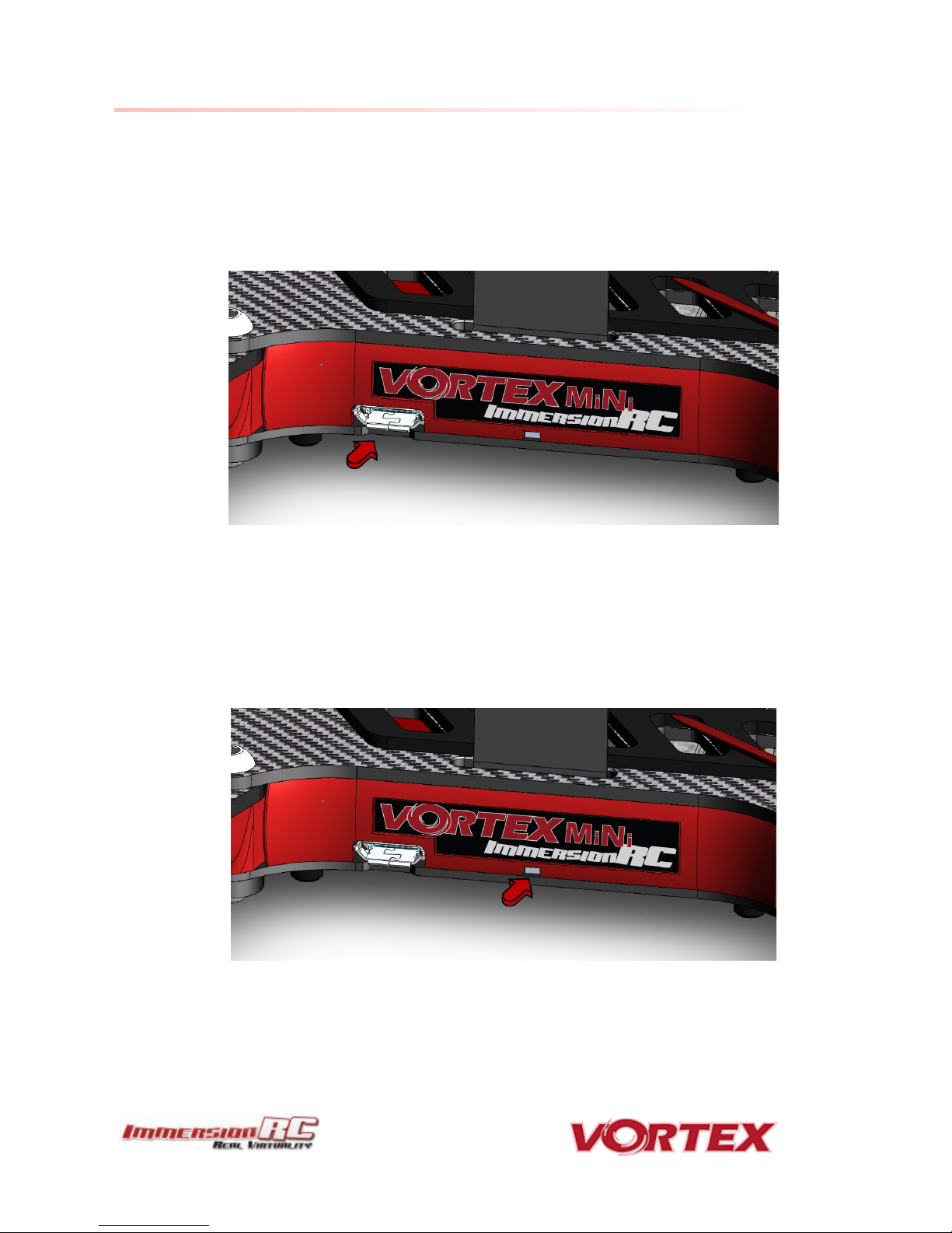
Connectors and Switches
1) USB connector, used to configure the flight controller and upgrade the Vortex firmware.
Note that when used with most USB hosts, a separate battery connection is not required when
connecting to the USB connector.
Please be careful not to put too much strain on this connector. It is a lightweight surface-mount part, and if the
quad is dragged around by the USB cord it may not survive.
2) Reset button, used to change Video Tx band, to restart the wizard and also to put a spektrum receiver in
bind mode.
Press and release after 1st beep to change video band, release after 2nd beep to restart the wizard,
release after 3rd beep to put a (non-autobind) spektrum rx in bind mode, finally release after 4th beep to
cancel operation.
Note: To bind a Spektrum Rx using the reset button, the vortex must be placed in SPEKTRUM 1024/2048 mode,
and not AUTO mode, using the Vortex Configurator on a PC or Mac.
Page 7
7
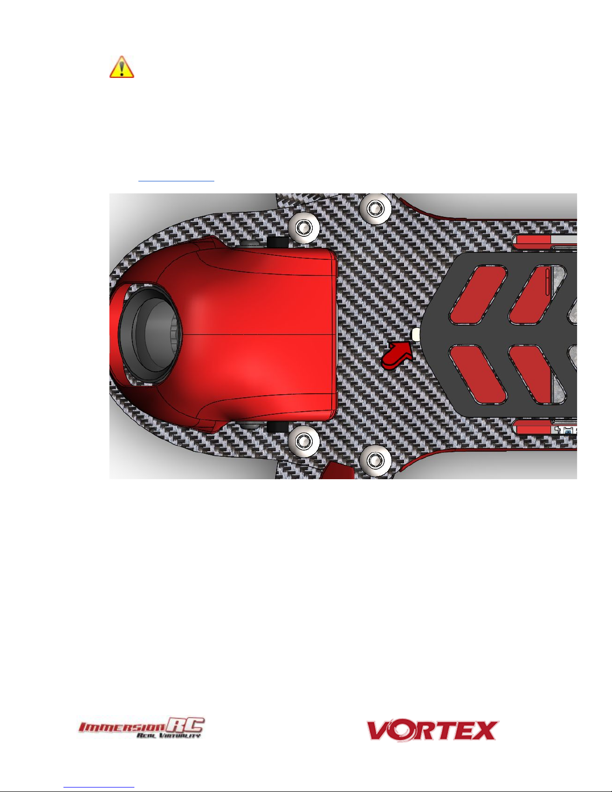
WARNING: Be careful how much pressure is placed on this small button. It is a surface-mount part which
may easily be damaged with a heavy-hand. Use an appropriate tool to access the recessed button (a bent
paper-clip works fine), and do not push harder after the first ‘click’ is felt.
3) Synergy FC/OSD button, used to enter firmware update mode in the case of a ‘bricked’ OSD. Note that
we don’t expect this button to ever be needed, but this is where it is located just incase...
See the
Firmware Upgrades
chapter for more details.
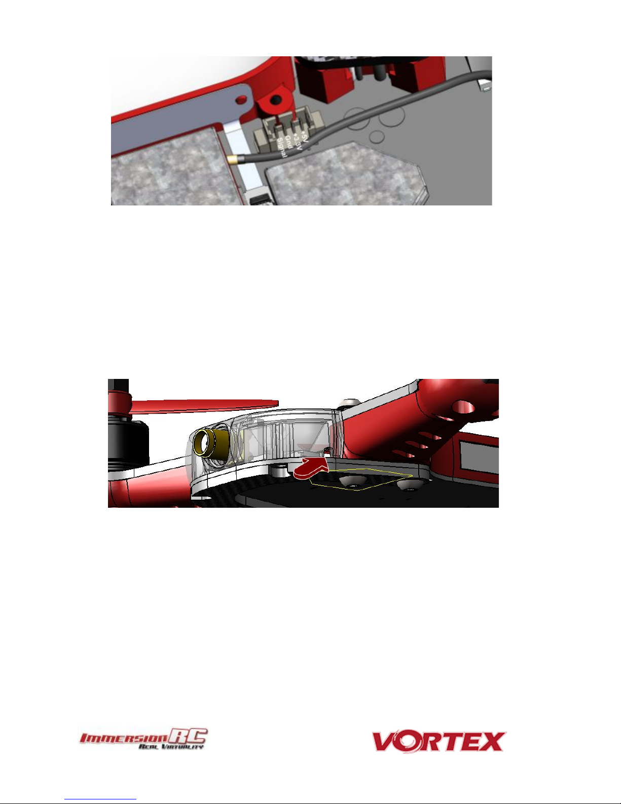
4) Receiver Connector (All Protocols, CPPM, SBus, DSMX™, etc.)
The Vortex 150 Mini has a single connector for all supported receivers. 5V and 3.3V power supplies are
available, to support most of the commonly used receivers on the market today. In most cases, one of the
supplied cables will suffice, but if a cable must be built, follow the pinout below:
Page 8
8
Note that a piece of double-sided tape may be used to secure the receiver on top of the metal can beside
the connector.
Receiver antennas may be routed through one of the 6 available slots. Two at the back of the quad in the
LED diffuser, and four in the side-plates.
In most cases the best solution is to route them through the rear, but certain receivers may experience
reduced range due to the close proximity of the 5.8GHz Tx antenna. If this occurs, consider relocating one
or both of the receiver antennas through one of the slots in the side-plates towards the front of the quad.
Page 9
Note 1: Pay EXTREME attention to the polarity of batteries connected to this connector, especially
those soldered ‘DIY’. A reverse-polarity connection, even for a fraction of a second will let out the
‘magic smoke’ and destroy most of the electronics in the Vortex Mini.
Note 2: When unplugging the battery, especially one with a new, and rather tight connector, take care
to hold the cables, and avoid unnecessary strain on the Vortex PDB. Pulling these cables too hard may
pull the traces off of the PCB.
Note 2: When unplugging the battery, especially one with a new, and rather tight connector, take care
to hold the cables, and avoid unnecessary strain on the Vortex PDB. Pulling these cables too hard may
pull the traces off of the PCB.
Note 3: XT-30 connectors are a lot less robust than their XT-60 cousins. Be careful not to force them
together with incorrect polarity. With enough force, the plastic shell will crack, and result in a destroyed
quad!
Cable
Description
Manufacturer’s PN
Digikey PN
FUN/GPS Signal Connector
Picoblade 5 pin
0510210500
WM1723-ND
Camera Signal Connector
Picoblade 3 pin
0510210300
WM1721-ND
Picoblade Signal Wires
(all Picoblade connectors)
Picoblade
0006660013
WM2320-ND
9
5) XT-30 Battery Connector
In order to reduce weight (and to arrive below the 250g weight limit for un-registered drones in the USA,
and other countries) XT-30 Battery connectors are used instead of the more popular XT-60s. It is highly
recommended to stick with this connector, and purchase batteries with XT-30s pre-installed. .
Connector Part Numbers and Sources
If any of the connectors on the Vortex 150 Mini are damaged, or if 3rd party components are to be integrated into
the system, the following list of connectors and pre-crimped wires should be useful.
Page 10

Note: The choice of soldered connections here, instead of the much more convenient connector option may
not seem ideal, but this is the best way to transmit the 20+ Amps of battery juice to the ESCs and motors
without losses.
10
Arm Assembly
When changing an arm, a soldering iron is required, to remove the ESC + and - battery cables, along with the signal
cable.
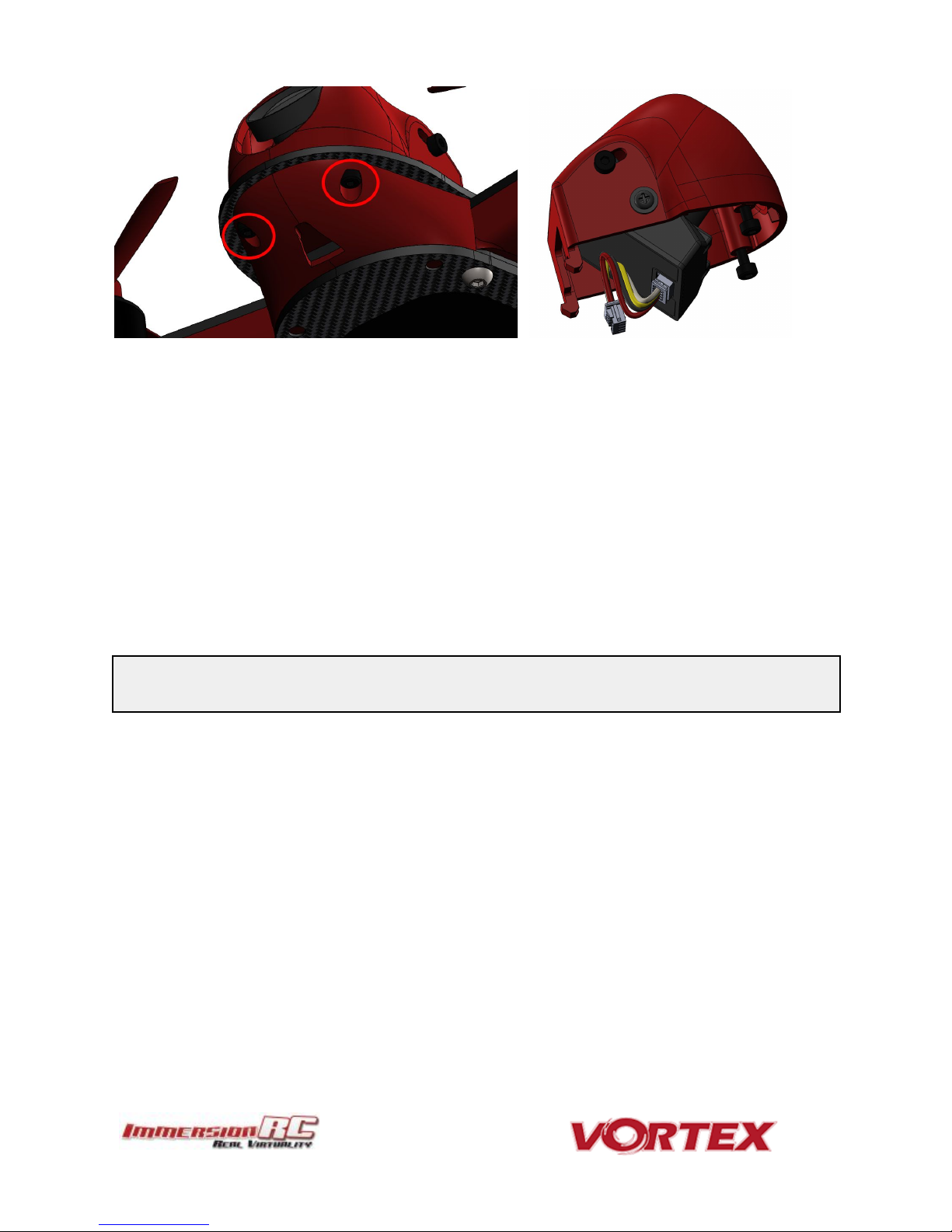
Camera Mounting
Flight Camera
The Vortex 150 Mini is equipped with a state-of-the-art FatShark 600 TVL CCD camera. This camera has custom
mounting points designed for race quads, which match up with the camera shroud.
To remove the camera, simply remove the two hex-head screws under the nose of the quad and tilt the camera
shroud upwards.
Carefully unplug the 4-pin camera connector from the PDB without putting too much strain on the cables.
Page 11
NOTE: The alarm is driven directly from the OSD on the 150 Mini, and not from the Flight Controller, so
changing beeper settings in the Betaflight configurator will not change its behavior.
11
Note that the camera tilt is adjustable. Loosen the two upper-screws and tilt the camera to the desired angle,
before re-tightening them.
Cool Feature Alert: The 150 Mini has a cool way to control the camera settings directly from the Vortex OSD.
Lost Model Alarm
The Lost Model Alarm on the Vortex 150 Mini sounds when the quad is disarmed after landing, or if a receiver
failsafe occurs.
The alarm is designed to be as simple as possible, without controls which could allow it to be accidentally disabled,
resulting in a lost quad.
Page 12
12
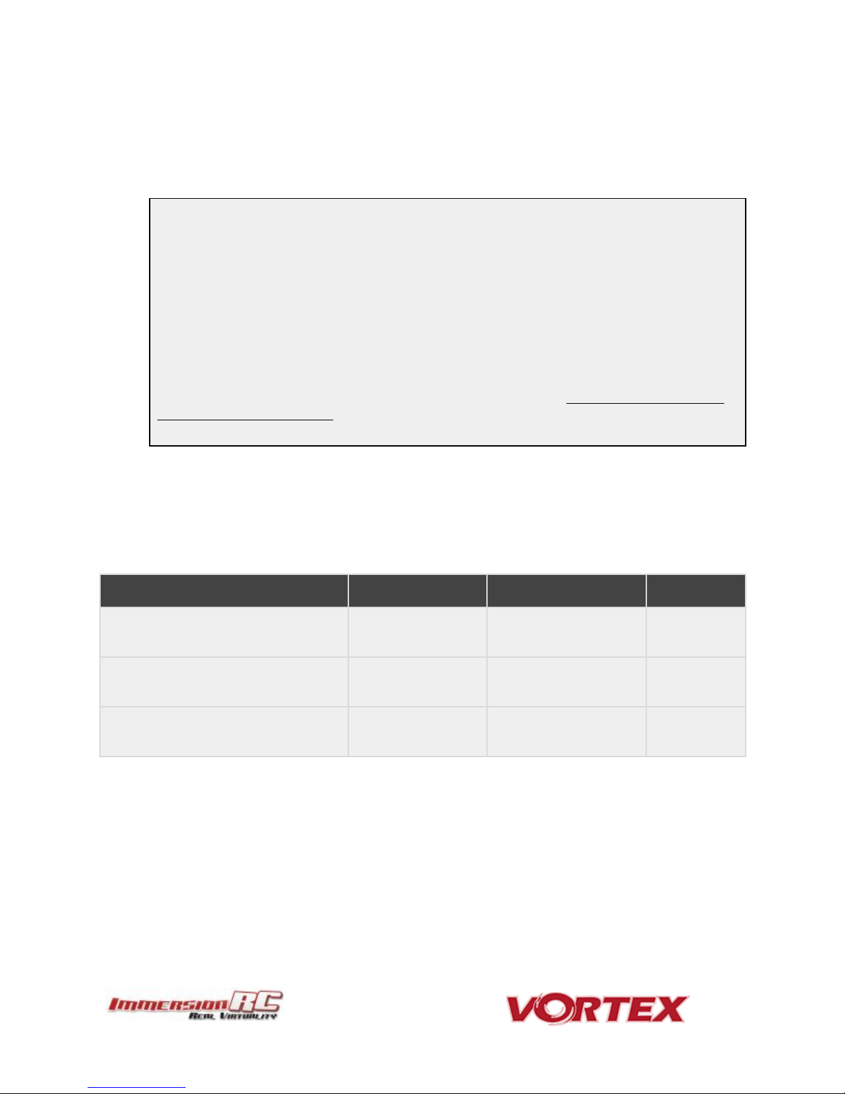
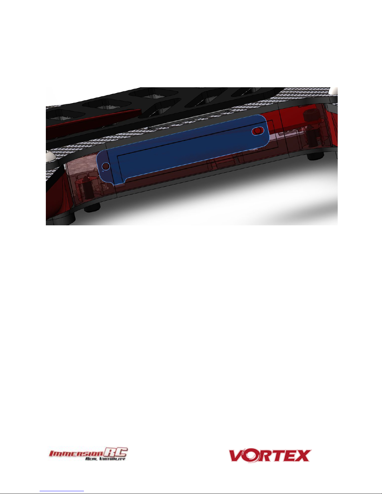
The Touch’n’Race (TNR) Tag
The Touch’n’Race tag is located behind the plastic side-plate of the right-side of the quad (looking from the back).
A TNR Wand may be used to not only query the video transmission frequency before powering-up the quad, but
also to set it to any of the supported channels before powering up.
Page 13
13
The On Screen Display (OSD)
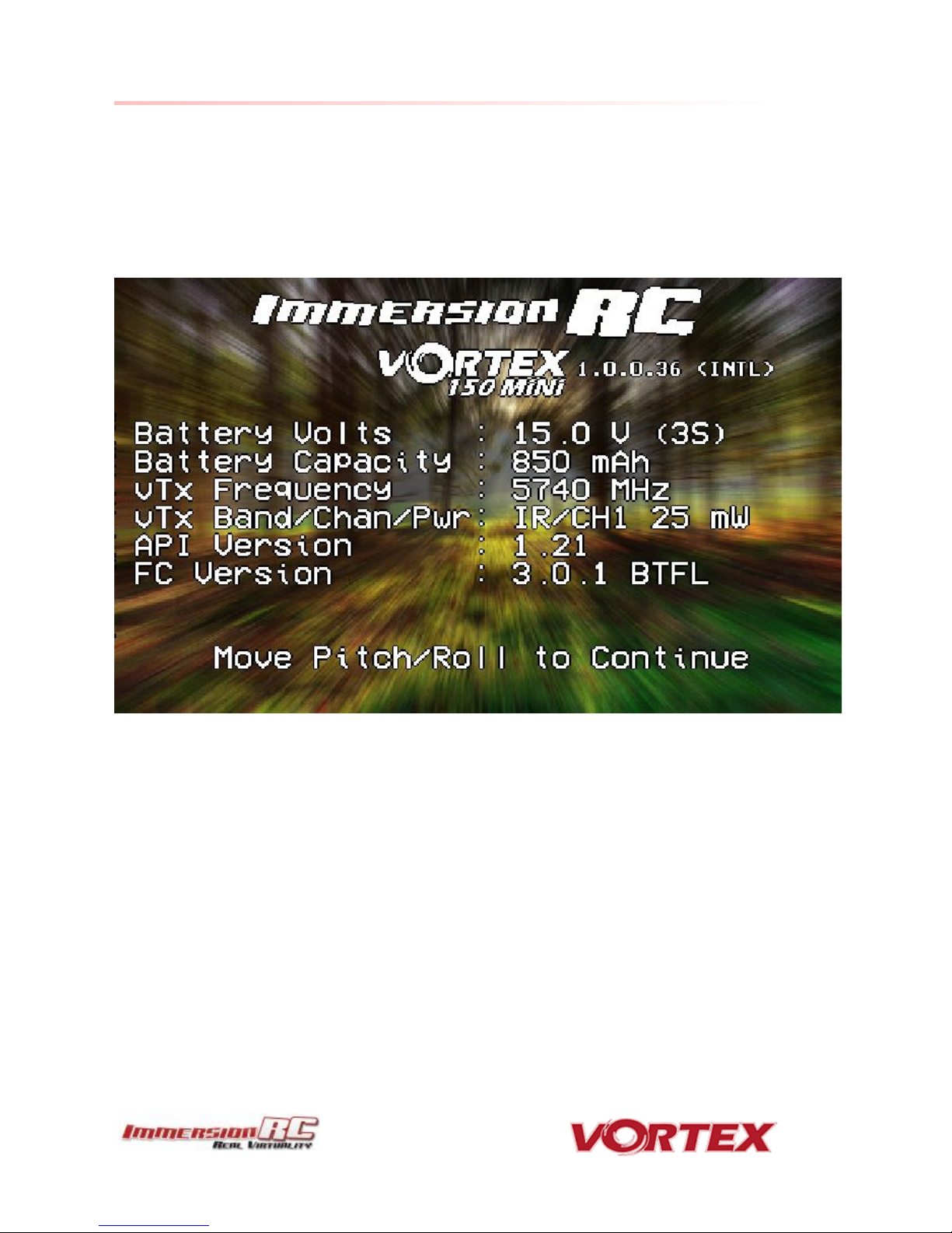
The Welcome Screen
Each time the Vortex is powered up, and before sticks are moved, the following welcome screen is displayed.
This shows various pieces of status information, including the Flight Controller version number, and Flight
Controller API version which is fairly important for OSD compatibility.
Moving the pitch/roll stick (right stick for mode 2’ers) will dismiss the menu.
Page 14

14
The Main Menu
For Mode 2’ers, holding the throttle stick down and to the left will enter the main menu. Note that this stick
position needs to be held for a few seconds before the menu appears.
Note that some menus are multi-page, take a look in the top-right corner of the display to see how many pages in
the current menu, and which is selected.
To navigate the menu, use the pitch/roll stick.
Page 15
NOTE: It is highly recommended to set this to match the flight pack that you are using to allow the OSD to
warn you when the battery is reaching critical levels.
15
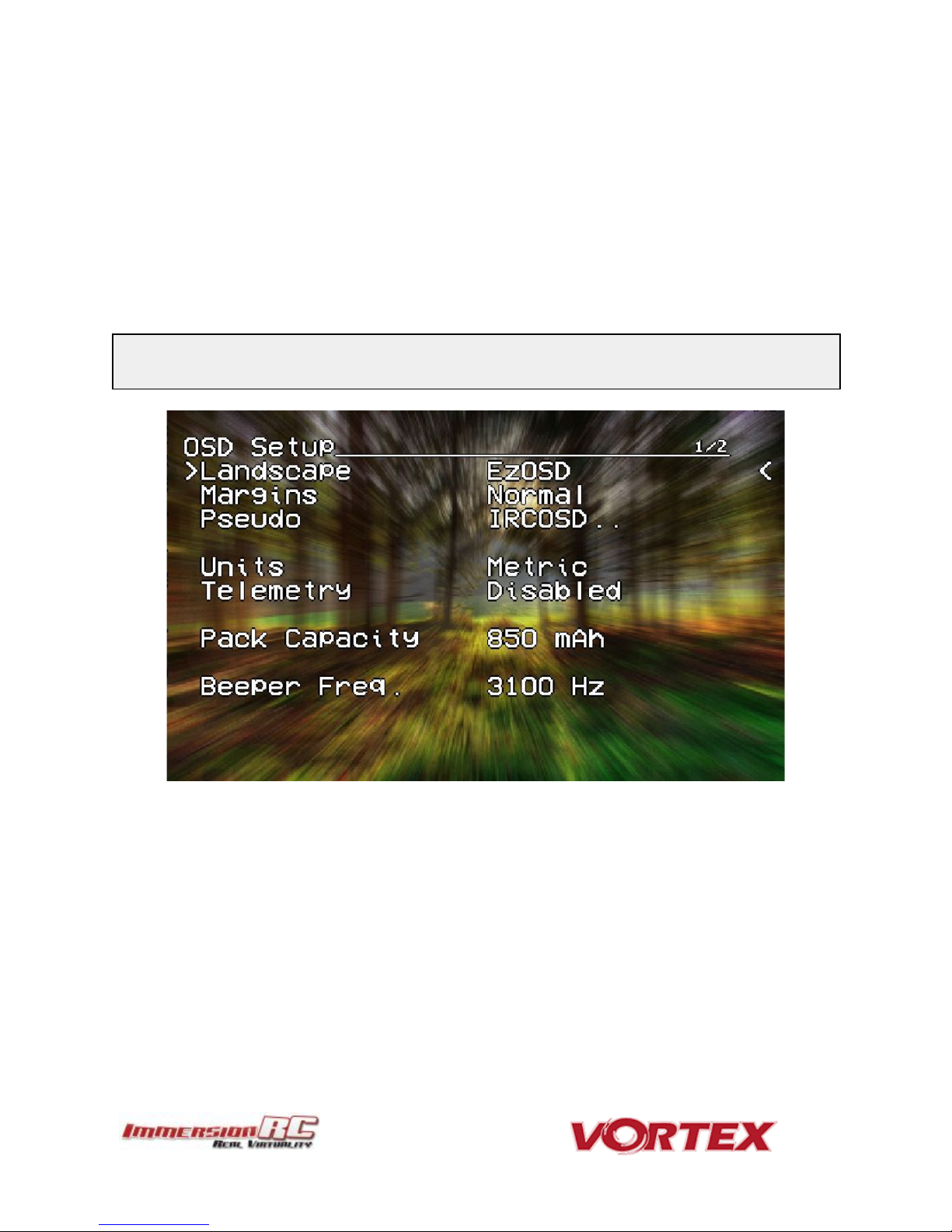
The OSD Setup Menu
Various OSD setup parameters are available in this menu.
The Landscape, defines the elements that are shown on the main screen in flight, including an EzOSD-type
landscape (the default), a clutter-free landscape for hardcore racers, and a gaming mode which is currently in Beta
form (documented later in this manual).
The Pseudo lets you name your quad. This is useful when several Vortexes are being used in a race, and simplifies
Video Tx channel assignments.
The Pack Capacity should be set to the capacity of your flight battery. The OSD will track battery consumption, and
will warn, with screen-center alarms, if it gets critical.
Page 16
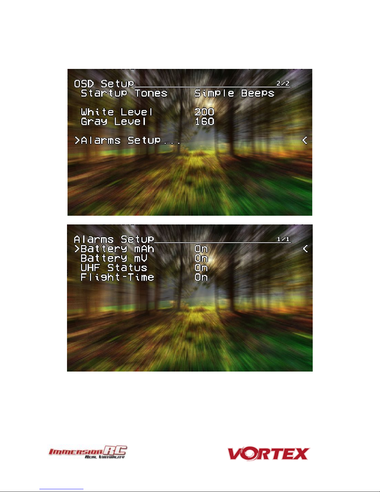
16
Alarms may be enabled and disabled in the Alarms Setup menu.
It is highly recommended to start flying with all alarms enabled, and disable them if required after getting used to
the quad.
Page 17
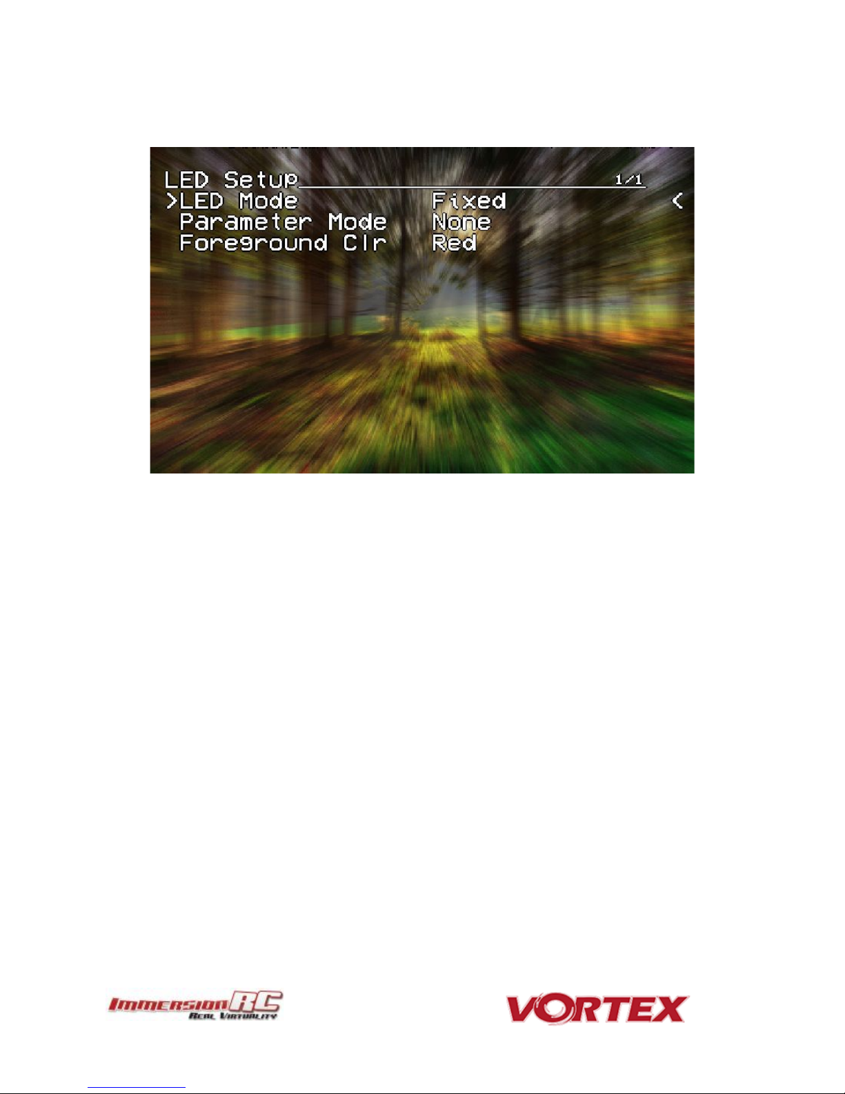
17
The LED Setup Menu
The RGB LEDs on the rear of the Vortex are fully programmable, with colors, and various patterns.
For Parameter Mode = Intensity, the intensity of the LEDs will reflect the current throttle position.
For Parameter Mode = Frequency the blink rate of the LEDs will reflect the current throttle position.
For Parameter Mode = Gradient, the LEDs will shift from the foreground color, to the background color, based
upon the current throttle position.
Other modes will be supported in future firmware updates.
Page 18
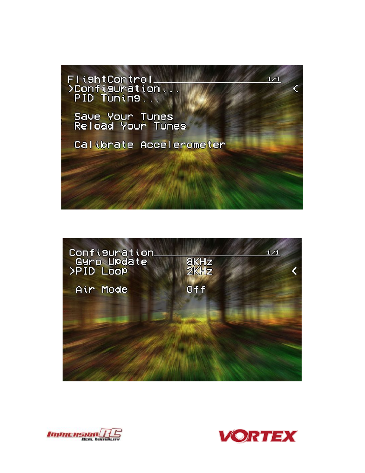
18
The Flight Controller Menus
In-field tweaking of flight-controller menus is possible without a laptop and USB cable.
All of the critical parameters, PIDs, Expos, Loop time, etc. are available.
General configuration settings should not need changing, except to enable Air Mode (which is highly
recommended).
Page 19

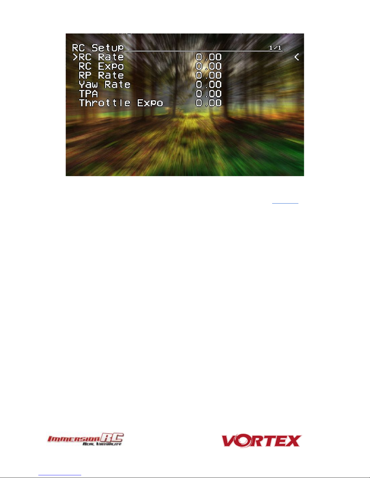
19
Note that the PID Settings menu is a two page menu, keep moving the caret down to access the second page.
Page 20
20
Note that all of the Flight Controller parameters can be preset by loading one of the installed Pro-Tunes.
Page 21
NOTE #1: There are several SKUs for the Vortex 150 Mini to allow sales in most countries. Each SKU may
limit power and/or available channels.
NOTE #2: The Vortex 150 Mini is always in ‘Dynamic Power Control’ mode. This limits output power to a
maximum of 25mW before takeoff, and after landing (disarming). Advantages are multiple, including much
lower battery consumption while waiting on the starting grid of a race.
21
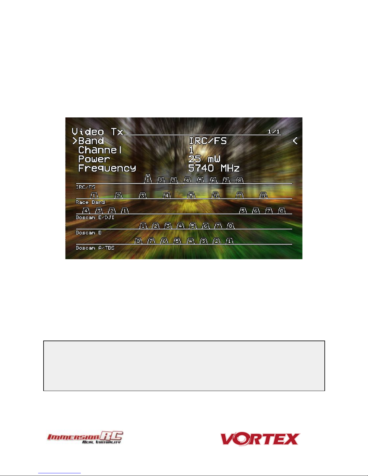
The Video Tx Menu
The Video Tx menu shows, graphically, the 5.8GHz frequency band, from low (left) through high (right) frequency.
5 bands are supported, covering the standard ImmersionRC/FatShark frequency bands, plus all of the ‘Boscam’,
Team Black Sheep bands, and also the new ImmersionRC ‘RaceBand’.
Note the need for RaceBand in this hobby is immediately obvious after looking at this graph!
NOTE: Channel 8 of the IRC/FS set cannot be received by 7 channel ImmersionRC or FatShark receivers. Unlocked
Uno/Duo5800 receivers can receive it, as can the new FatShark 4-band RaceBand Dominator module.
WARNING: Please play attention to the legality of the channels that you are using in your area.
While the authorities have been relatively tolerant of emitted power on 5.8GHz, out of band transmission is a more
serious issue.
In the USA, with a Ham license (required to emit more than about 1mW), operation within the 5650MHz to 5925MHz
band is allowed. All 8 RaceBand channels fall within this band, but the outer channels of the Boscam E band are outside
the band.
Within Europe, the Ham band is 5650MHz to 5850MHz, which allows the first 6 RaceBand channels.
Page 22
22
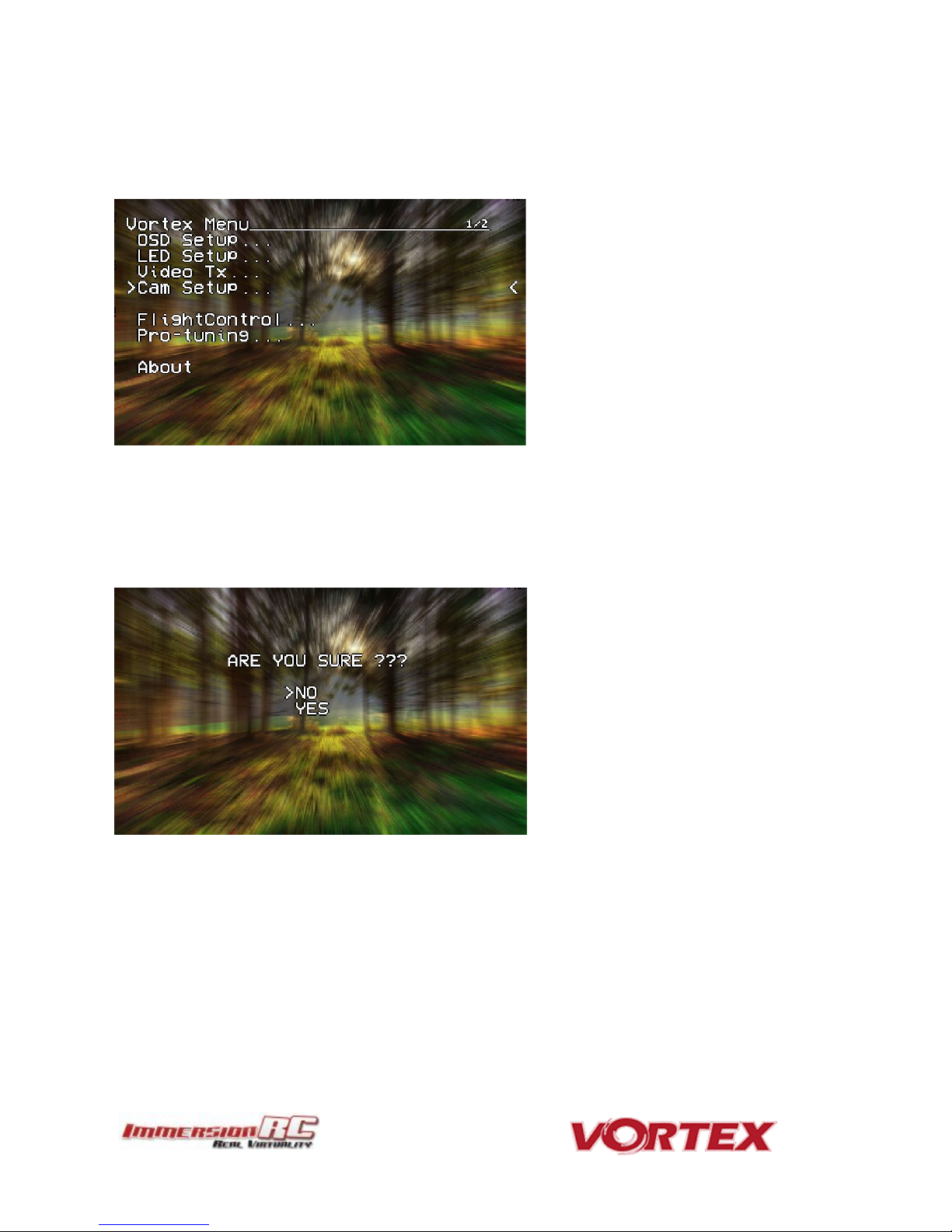
The Camera Settings
The Camera Settings menu allows the camera settings to be modified using the camera’s built-in OSD.
Ideal for tweaking settings to optimize the camera for challenging lighting conditions.
A confirmation prompt appears before entering the camera’s OSD menu. When selecting YES, the OSD controls
will change slightly from those used in the Vortex OSD.
For Mode 2 users, the right-stick becomes the OSD setup joystick (up/down/left/right), and the Vortex OSD ‘Enter
Menu’ control (left stick back and left) becomes the ‘select’ function.
A long ‘Enter Menu’ control (1 second or more) returns control to the Vortex OSD.
Page 23

23
Video Transmitter
The Vortex 150 Mini flight controller/OSD board contains an embedded ‘Tramp’ 5.8GHz Video Transmitter.
The frequency, and power level of this transmitter may be programmed using several techniques (several of which
are unique to this product), including:
1) OSD Menu selection (while powered up)
2) TNR Wand (even when powered down)
3) PitStick set after power-up using the R/C remote.
4) DSMX control from a supported Spektrum R/C Transmitter
OSD Menu
The OSD Menu is the ‘traditional’ Vortex method of configuring the video transmitter. The quad is powered up,
transmits on it’s last configured channel, and by entering the OSD menu, the channel may be changed.
TNR Wand
The TNR Wand method is new for the Vortex 150, and allows the video transmitter to be configured before
powering up the quad. This enables the wonderful feature of arriving at a park or race, asking your flying buddies
what channels they are using, and picking a clear channel before powering up.
The TNR feature also supports the Race Director’s wand ‘Race Lock’ and pit mode, where quads may be integrated
into race events in the same way as the Tramp HV.
NOTE: The TNR Wand feature of the 150 requires a wand either from the second production batch (v1.1), or a modified
wand from the first batch (v1.0).
PitStick Mode
The new PitStick mode, unique to the Vortex 150 Mini, is enabled using the Video Tx menu, selecting the required
band (typically RaceBand), and then selecting ‘PitStick’ as the channel number.
When in this mode, the quad will not transmit at all when powered up, but will instead play a tune occasionally
after power-up to remind the pilot that PitStick is active.
For Mode 2 users, use the right stick to select the channel number, as shown below (channel 1 is straight up, each
45 degree step around the clock is another channel number).
No wand required, No OSD settings each time you arrive at the field, just power up, and set the channel using the
R/C Controller.
Page 24

Note: To use DSMX to set the Tx settings, but not transmit immediately at power-up, select the PitStick
channel following the procedure above.
Compatible Radios
DX6e
DX6 G2, G3
DX7 G2
DX8 G2
DX9, DX9 Black
DX10t
DX18t
DX18
DX18 G2
24
DSMX Mode
For the DSMX mode, several of the more recent Spektrum™ radios (see table below) can set the video transmitter
channel using the LCD directly on the radio.
An example of the settings from the DX9 are shown below.
Set the channel, band, and power level from the LCD, and select ‘Send’ to send the settings to the Vortex.
The following Spektrum™ radios are either compatible out of the box (DX6e) or may be upgraded to support the
vTx control menu. To create an account on the Spektrum site, and register your radio, visit the following site:
https://www.spektrumrc.com/MyAccount/Register.aspx
Page 25

Pitch
Throttle Yaw
Roll
Throttle
Pitch
Yaw
Roll
Pitch
Throttle
Roll
Yaw
Throttle
Pitch
Roll
Yaw
25
Flight Controller
R/C Transmitter Control Modes
Mode 1 - Common in Europe
Mode 2 - Common in the USA
Mode 3
Mode 4
Page 26

Acro
This mode is the preferred mode for the more advanced mini-quad pilot.
In many ways it is the simplest mode, but also the hardest mode to learn.
In Acro mode, the accelerometer part of the IMU is not used, only the Gyro.
Because of this, the quad will not self-level, explaining the steep learning curve for this mode.
To learn this mode, it is recommended to start flying the quad FPV, in Angle mode, get some
altitude, and switch into Acro mode.
Landings in Acro mode can be a bit challenging for the beginner, so switching to Angle mode before
landing is a reasonable way to deal with this.
Acro mode is the ideal mode to have fun with flips and rolls.
Angle
Angle mode is the easiest to learn. When the sticks are centered, the flight controller is always
working to level the quad.
The deviation of the Roll/Pitch controls from neutral defines the angle of the quad in flight.
Not a great mode for racing, but definitely the mode to use for the maiden flight.
Horiz
Horiz mode is a bit of a hybrid mode. It does auto-level, but also allows flips and rolls.
26
Flight Modes
Three flight modes are configured by the Vortex Wizard, and are mapped by default to channel 5 of the R/C Tx.
These modes are as follows:
Page 27
NOTE: Do not install new Betaflight builds, nor builds of other Flight Controller software, without first
verifying that they are supported by the Vortex OSD.
NOTE: When Vortex will detect a new flight-controller version, it will automatically restart in TX Wizard
mode.
27
Betaflight Open-Source
The development of the Vortex would not have been possible without the effort of a large team of individuals who
invested in the open source flight controller software that running on the Vortex.
The variant of the open source flight controller firmware that we chose to power the Vortex is Betaflight, mainly
due to it’s solid support of the OneShot ESC control protocol.
Since the OSD firmware needs an intimate knowledge of the flight controller API, care must be taken when
installing updated Betaflight builds (IRCSYNERGYF3).
The ImmersionRC team may not have support for Beta, and recently released Betaflight builds the day they are
released, but we are committed to keep up with changes.
Check the ImmersionRC Vortex product page for compatibility information.
Betaflight Configurator Connection
To hook up the Betaflight Configurator, hook up a Personal Computer via a standard Micro-USB cable, to the
connector on the back of the Vortex.
Be aware that making certain changes via the configurator may break compatibility with the Vortex OSD. One
example would be changing the channel order, which is set by the wizard.
Re-running the Vortex setup wizard will reset the Betaflight configuration to defaults.
Page 28

28
Flight Controller Stick Commands
Enter Menu/Disarm Flight Controller:
Mode 2: Throttle stick left, and down (normal flight controller disarm control)
Mode 1: Yaw left, Throttle stick down
Arm Flight Controller:
Mode 2: Throttle stick right, and down
Mode 1: Yaw right, Throttle stick down
Reset vTx Channel:
Mode 2: Throttle Down, Rudder Left
+ Elevator Up, Aileron Left
Mode 1: Throttle Down, Rudder Left
+ Elevator Up, Aileron Left
Page 29
NOTE: The first generation of EzESCs cannot have their firmware upgraded by end-users. Upgrading them
requires special equipment, used in the factory, and at ImmersionRC repair centers.
NOTE: This procedure may be performed with props in place, or props removed. For safety’s sake it is
recommended that props are removed.
If they are left installed, it is recommended to use a stick, or other object instead of a finger to flick the prop.
IMPORTANT: ImmersionRC ESCs DO NOT REQUIRE CALIBRATION. The calibration process required by most
‘budget’ ESCs is required since a precise quartz oscillator is not used in the ESC. The ImmersionRC ESCs all
include this critical component, and therefore never need calibration.
29
ESCs - The 16A Vortex 150 ESC
Overview
The ESCs used in the Vortex Mini are a full-custom design, which uses a potent 32-bit ARM processor.
They are small enough to be enclosed completely in the plastic ESC covers of the Vortex 150 Mini, where they are
well protected against the elements, and from physical damage from passing tree-branches.
The ESCs come pre-configured for all motors supported by the Vortex, and they have also been used successfully
with various aftermarket motors used by our test team.
RotorSENSE
A unique feature of the ESCs used in the Vortex is RotorSense.
This feature puts an end to the decade-old ‘wire-swapping’ technique used to get brushless motors to spin in the
correct direction.
Once props are installed, at power-up before arming the flight controller, a simple spin of a prop will program the
rotation sense.
The full procedure is as follows:
1) Cycle power to the quad to ensure that the flight controller is not armed.
2) Spin the motor in the desired direction. If the ESC recognizes the spin, two short beeps will be generated.
3) Spin the motor again in the desired direction. If the ESC recognises the spin, 5 longer beeps will be
generated and the ESC has learned the direction.
Page 30

NOTE: The default ‘pro-Tune’ loaded is Bewweb pro-tune for beginner. For experienced racers, who require
more ‘crisp’ flight characteristics, it is recommended to load the UmmaGawd tune.
30
Pro-Tuning
During the development of the Vortex, a team of pro-quad pilots spent countless hours, tweaking the tuning (PIDs)
of the flight controller, using various ‘PID Controllers’ supported by the Cleanflight firmware
Each pilot fed back this data to the ImmersionRC team, and we incorporated it into the OSD firmware.
Now, as a user, you can choose your favourite pilot, choice of props, battery, flight style, etc. and all flight
controller settings are configured for you, based upon his pro-tune.
Thanks to these pilots, you will spend less time in the field setting up the flight controller (quite an art), and more
time racing.
Page 31
31
R/C (Uplink) Receiver Selection
The Vortex 150 Mini is shipped with three receiver interface cables, supporting 4 commonly used interfaces.
a) 3-Pin 0.1” Servo Cable, for S-Bus, and CPPM (5V)
b) 5-pin Picoblade for FrSky XSR receivers (5V)
c) 3-pin JST-ZH for Spektrum DSMX receivers (3V)
Receivers may be mounted externally on the tail-end of the quad, or internally. Internally is definitely the preferred
solution but does require a suitably small receiver.
The following are recommended for internal installation:
1) FrSky XSR, using the supplied XSR cable
2) FrSky X4R-SB, ‘Naked’ version with SBus output
Requires some soldering to wire sbus cable
3) Spektrum SPM4648 Auto-bind receiver with supplied DSMX cable
Remove plastic case and heat-shrink for optimal fit
4) Spektrum SPM9646 Carbon fuse receiver
5) Spektrum SPM9649T Telemetry receiver
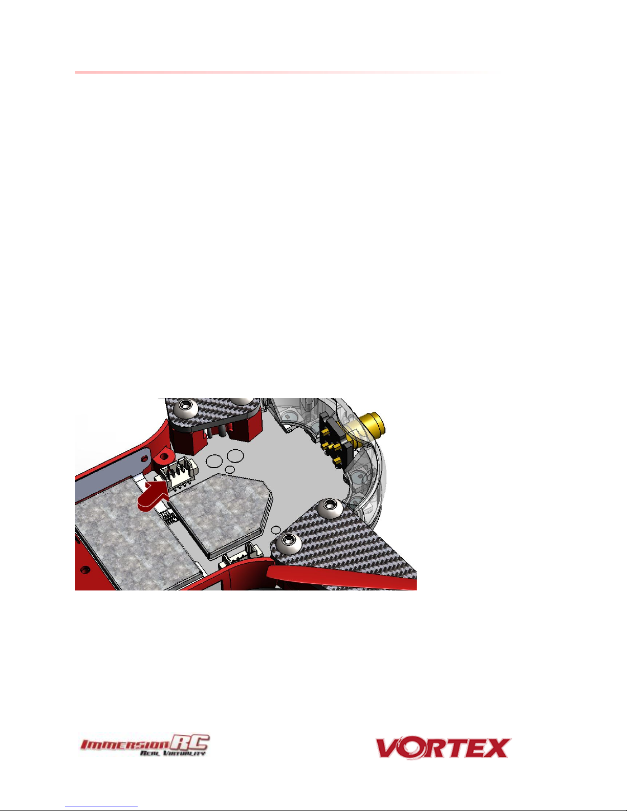
To access the receiver bay for internal receiver mounting, remove the 8 screws which secure the top plate to the
arms, and carefully remove the top assembly, which includes the camera unit.
The receiver connector is indicated by the red arrow below. To mount the receiver, a small piece of double-sided
tape may be used on the top of the metal can in the receiver bay.
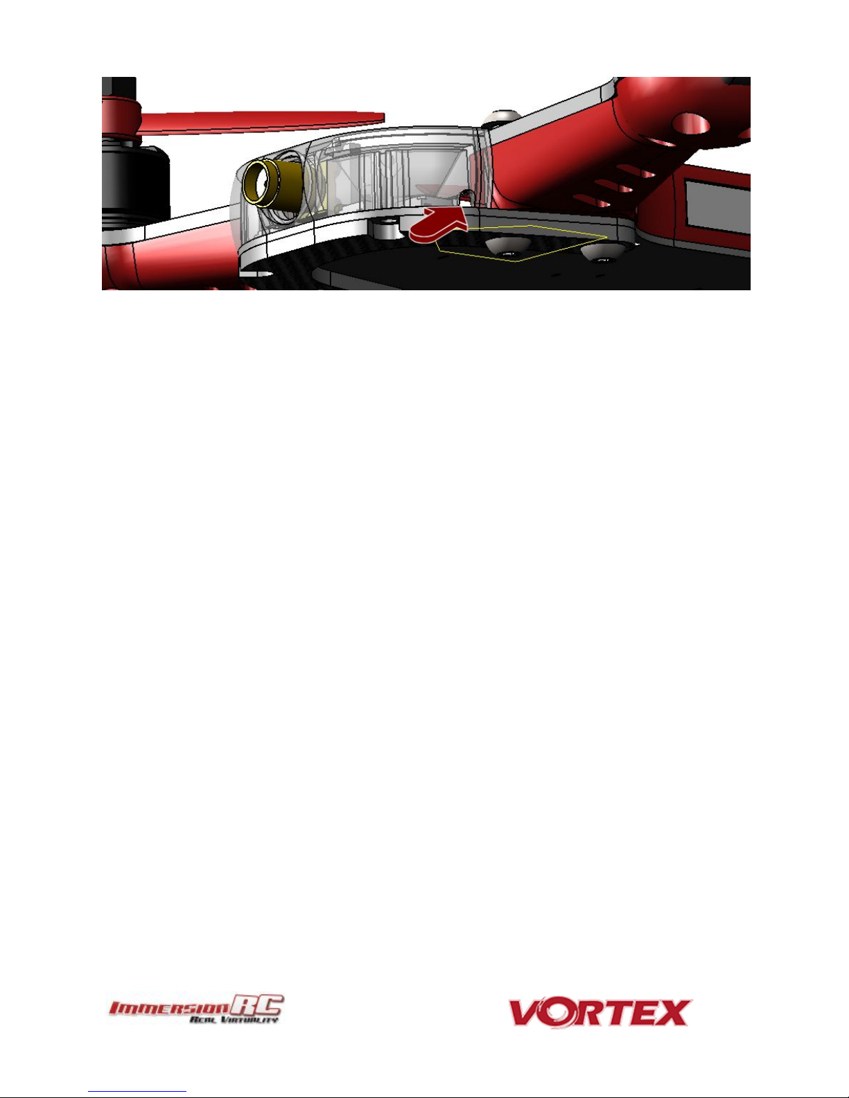
Finally, the receiver antennas may be routed through the two notches in the bottom of the LED diffuser.
Page 32
32
Notes on Receiver Selection
One critical parameter to keep to a minimum in a race quad setup is latency. Latency from what the camera sees
to the display device, and also from the control stick to the flight controller.
For minimum latency, with reasonable range, the Spektrum™ radios and satellite receivers are a great choice.
Another good (and quite common) choice is the FrSky Taranis radio with a matched S-Bus receiver (X4R for
example).
Page 33

33
Receiver Auto-Detection
A unique feature of the Vortex family of quadcopters is that the receiver type is auto-detected by the OSD when
running the wizard.
R/C Transmitter Configuration
The advanced wizard used in the Vortex 150 Mini is cable of detecting most transmitter configurations. Channel
ordering, stick range, center position, etc. are all learned by the wizard.
In most cases it is better to start from a ‘default’ model on the R/C transmitter. On the Taranis, select the
quadcopter option, and leave all settings as defaults.
Race Guidelines - Flying with Friends
The current generation of FPV Analog video link brings many advantages. Low-cost, and zero latency being two of
the most significant.
They do however suffer from less than ideal ‘selectivity’, even when using large channel spacing as is the case
with RaceBand.
If a few simple rules are followed, quad racing can be a lot of fun.
1) NEVER land near another pilot.
This is an absolutely golden rule. Landing your quad near another pilot, especially one who is at a
significant distance, is like screaming in the ear of someone listening to a whisper at the other side of a
room.
2) NEVER walk back to the pilot area with a powered-up quad
This is similar to 1), and is the most common cause of issues at the race track.
When retrieving a model, unplug the battery before walking back to the pilot area.
3) POSITION the launch and landing zone as far from the pilot area as possible
This ensures that collisions at race start don’t affect other pilots.
A distance of at least 10 meters is recommended, more than this is a bonus.
4) ALWAYS warn in-air pilots before powering up a quad, even if you KNOW it is on a different channel
Warn pilots, and be ready to power down IMMEDIATELY if a pilot is affected, and wait until he lands.
Remember that it only takes a second or two, when flying race quads at speed, to crash and damage the
quad, and whatever (whoever) it hits.
Page 34
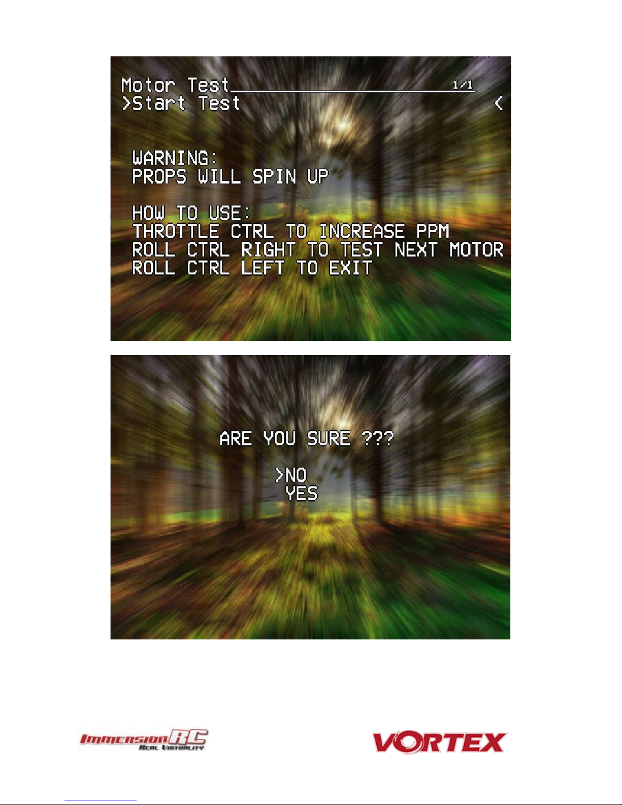
WARNING: This test can be extremely dangerous, great care is required.
The Vortex should be securely anchored to an immovable object, ideally one which doesn’t block the airflow under
the props.
Holding the Vortex during the motor tests is highly in-advised!
34
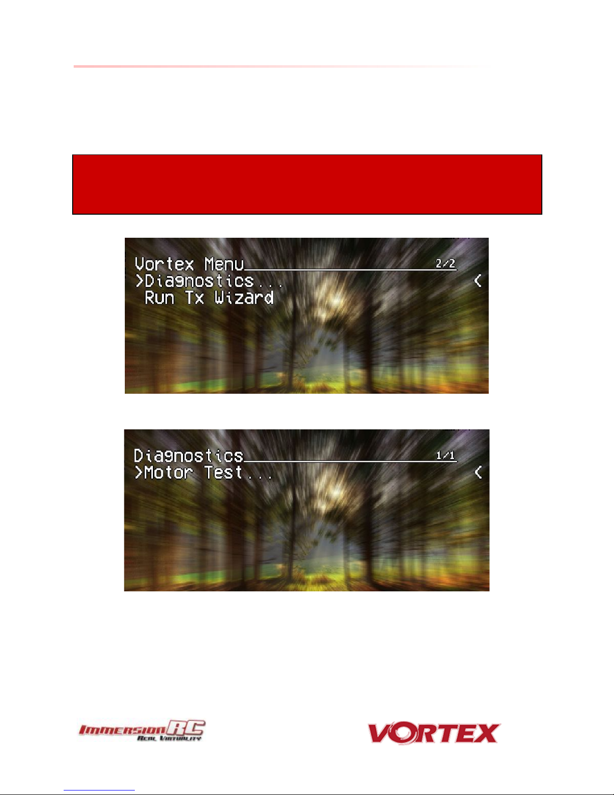
Diagnostics - Motor Test
The Vortex 150 Mini has a built-in diagnostic motor test. It can be useful to diagnose problems with ESC and\or
Motors.
It’s located in Vortex Menu>Diagnostics>Motor Test
Page 35
35
Page 36

36
Motors will be tested independently in sequence, and then all together.
Use the roll stick left to go to next steps:
Motor1 -> Motor2 -> Motor3 -> Motor4 -> All Motors -> Test Summary
The summary screen and the graph could help you to identify a damaged motor:
Page 37

In-house test results on the latest fad in motor development where curved magnets are used, and
stator/magnet gaps are minimized have not provided great results with the 150 to date, and should probably
be avoided.
37
To exit the test move the Roll stick to the left.
Hardware Upgrades
The Vortex 150 Mini was intentionally equipped with brushless motors which are suitable for beginners to the
hobby, or for more advanced pilots to enjoy themselves around some tight tracks.
For experienced pilots who want a bit more performance there are a slew of available motor upgrades. One that
we can highly recommend is the X-Nova 1407-3500kV, 100% compatible with the standard ESCs, compatible with
the provided mounting holes in the arms, and ideal to swing the stock 3” props.
Page 38

38
Appendix A: Firmware Upgrades
Both the OSD, and the Flight Controller, are updated using the USB port on the rear of the Vortex.
Prior to any upgrade, please remove all Props!. If for any reason the props spin up during a firmware upgrade,
serious damage to persons and/or property is very likely.
If your Vortex is not recognized as a valid USB device when you plug it in your PC, you will have to install a driver
first. You can download it from here: CP210x USB to UART Bridge VCP Driver
To update the OSD and Flight Controller you will need to install two chrome applications:
1. vortex-configurator
2. Betaflight-configurator
OSD Firmware Upgrades
To upgrade the OSD, use the new vortex-configurator chrome app.
Please note that you need to rerun the Tx wizard after each up- or downgrade of the OSD firmware to make sure
that the FC and OSD know the range and endpoints of your controls. Failure to do so might result in the OSD being
unresponsive to the quad exhibiting strange behavior.
Page 39
NOTE: If it failed, wait 1 seconds and retry by clicking Flash Firmware.... Sometimes it may need few
attempts before it starts flashing, so keep trying few times.If after 5 retried it's still not working, retry the
entire procedure.
NOTE: Upgrading Betaflight to a version not supported by the OSD firmware can easily result in the OSD not
functioning. Please refer to the Vortex product page on the ImmersionRC website for compatibility
information.
NOTE: When Vortex will detect a new flight-controller version, it will automatically restart in TX Wizard
mode. If not, force the TX Wizard using the Vortex app.
39
Upgrade procedure
1) Remove props, connect a Lipo.
2) Attach the Vortex to a Windows PC or a Mac using a standard Micro-USB cable (ensure that this is a full
USB cable, and not a power-only cable shipped with some products)
3) Start vortex-configurator from chrome://apps/
4) Make sure the right COM port is selected and press the Flash Firmware button.
5) Point to the update file (OSD_vX.X.X.X.fw) downloadable from the Vortex 150 product page on the
ImmersionRC website, and start the update.
If during a previous upgrade you had a problem causing the OSD to be bricked, you can still recover from this state
using the procedure below:
Upgrade procedure for bricked OSD
1) Press and hold the button on top of the synergy flight controller (accessible through a hole in the front of
the battery pad).
2) Remove props, plug in the Lipo ( while still holding the fusion board button ).
3) Release synergy board button after 2 seconds.
4) Plug to USB
5) Start vortex-configurator from chrome://apps/
6) Make sure the right COM port is selected and press the Flash Firmware button.
7) Point to the update file downloadable from the Vortex product page on the ImmersionRC website, and
start the update.
Flight Controller Firmware Upgrades
To upgrade the Flight-Controller firmware, the same Vortex Configurator tool may be used.
Simply select the BetaFlight .hex file instead of the OSD .fw file when flashing. use the betaflight configurator. :
Page 40

Flight Controller
Failsafe
Enabled, Throttle set to 1100
OneShot125
Feature Enabled
Rx Mode
PPM Sum Mode (all channels down a single cable)
Minimum Throttle
1100us
Maximum Throttle
1900us
Minimum Command
1015us
Angle mode on Aux1
1300 - 1700us
Horiz mode on Aux1
900 - 1300us
Acro mode on Aux1
1700 - 2100us
Channel Mapping
According to Wizard prompts
Accelerometer
Calibrated at wizard end
Pro-Tuning
Default ImmersionRC settings (based on UmmaGawd’s tune)
NOTE: If you have ‘tweaked’ any Betaflight settings outside of the Vortex OSD, please remember to back
them up before running the wizard the next time, since it will reset them to default settings.
40
Appendix B: The Wizard - What else does it setup?
On startup the wizard will reset Betaflight configuration to its default state.
Once completed the following features, configurations and mode will be injected in Betaflight so you can start to
enjoy your Vortex straight off the box with zero additional configuration needed:
Appendix C: Video Tx - Staying Legal
Depending upon the Vortex variant purchased, and the Tx module installed, the video transmitter power output
level, and available transmit frequencies can vary.
It is highly recommended to understand the rules and regulations in your country before using the Vortex.
Transmitting outside a legal band is something frowned upon by the authorities, and may result in a fine, or
confiscation of equipment.
As a rule of thumb, the following charts should help understand which frequencies are legal in each of our main
markets.
Page 41
1 2 3 4 5 6 7 8 1
5740
5760
5780
5800
5820
5840
5860
5880
IRC/FS
2
5658
5695
5732
5769
5806
5843
5880
5917
RaceBand
3
5705
5685
5665
5645
5885
5905
5925
5945
Band E
4
5733
5752
5771
5790
5809
5828
5847
5866
Band B
5
5865
5845
5825
5805
5785
5765
5745
5725
Band A
41
ITU Region 2: Americas, Greenland, eastern Pacific Islands
Assuming that the user has a Ham license, the 5650 - 5925 MHz band may be used.
Note that all 8 channels of ImmersionRC’s RaceBand are legal in in this region, with a Ham license.
With the FCC power limit for analog transmissions being so low for license-free use, it is not very interesting for
race quad use. At present, ImmersionRC does not ship a ~1mW version of the Vortex transmitter module. This
may change in the future.
Page 42

1 2 3 4 5 6 7 8 1
5740
5760
5780
5800
5820
5840
5860
5880
IRC/FS
2
5658
5695
5732
5769
5806
5843
5880
5917
RaceBand
3
5705
5685
5665
5645
5885
5905
5925
5945
Band E
4
5733
5752
5771
5790
5809
5828
5847
5866
Band B
5
5865
5845
5825
5805
5785
5765
5745
5725
Band A
1 2 3 4 5 6 7 8 1
5740
5760
5780
5800
5820
5840
5860
5880
IRC/FS
2
5658
5695
5732
5769
5806
5843
5880
5917
RaceBand
3
5705
5685
5665
5645
5885
5905
5925
5945
Band E
4
5733
5752
5771
5790
5809
5828
5847
5866
Band B
5
5865
5845
5825
5805
5785
5765
5745
5725
Band A
42
ITU Region 1: Europe, Africa, Middle East, Iraq, Soviet Union
Without a license, only the 25mW Tx module may be used, and then only in the ISM band from 5725 MHz thru
5875 MHz.
ITU Region 1: Europe, Africa, Middle East, Iraq, Soviet Union
With a Ham license, the legal band varies widely from country to country, but taking France as an example, Ham
users may use the band 5650 through 5850 MHz with more than 25mW.
Page 43
43
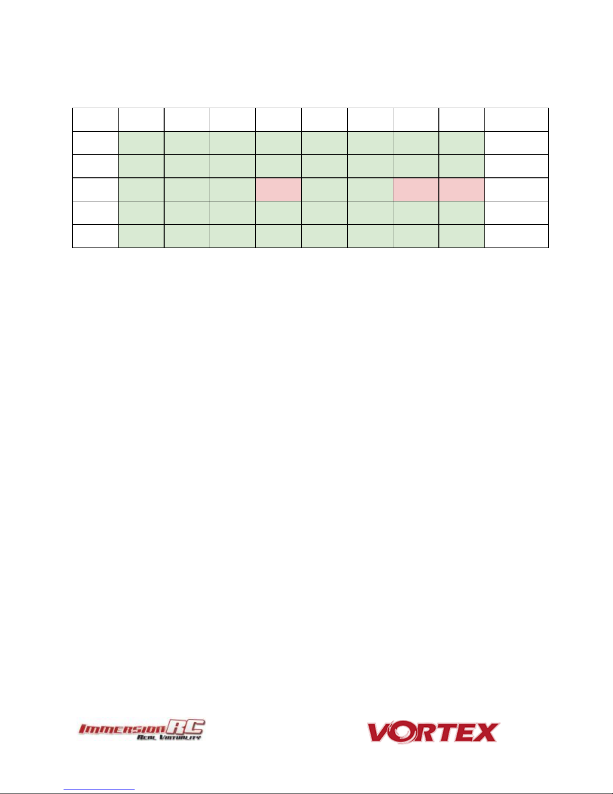
Appendix D: LED Board - Status report
The RGB LEDs on the rear of the Vortex 150 Mini are used by the OSD during the startup phase to report flight
controller sensor status, FC API compatibility, and video link status information.
From left to right the bottom led board will turn green ( or red if a problem is detected) one after another as
follows:
1. GYRO sensor detected
2. ACCEL sensor detected
3. Flight Controller/OSD APIs Compatible
4. Camera detected
At the end of the initialization sequence, the led board will blink in green if all tests passed, or it will blink in red if
any test failed.
It will also blink in green for 3 seconds when you arm your Vortex.
Looking after your Vortex
Snow and Water
Even though most of the PCBs in the Vortex are coated with a conformal coating, which does offer some
protection from water, it is not recommended to get the Vortex wet, even if that water comes in the form of snow.
If your Vortex does get wet, immediately remove power, and place it in a sealed container containing uncooked
rice, for 24 hours. The rice will absorb some of the water.
If the Vortex falls into salt water, damage may be more serious, and requires rinsing the quad with a bath of
distilled water before placing it in the sealed rice container. The Tx module may not survive this ordeal, and may
require replacing.
Note that even if the Vortex survives a salt-water bath, long term corrosive effects of the salt on any exposed
copper surfaces may result in the product failing at some point in the future.
Page 44

44
The Sun
The camera use in the Vortex (or any camera for that matter) does not appreciate being left staring at the sun for
long periods of time.
LiPos also have a habit of living short lives when exposed to extreme heat.
It is highly recommended to store the Vortex in the shade between flights.
Dirt
The typical mini-quad tends to live a life coated in a thick layer of grass, dirt, and other materials which happen to
be in the way during landings, whether intentional, or otherwise.
It is highly recommended to keep the Vortex clean of foreign materials, especially those which tend to conduct
electricity when wet.
A toothbrush is the best tool to keep your Vortex 150 Mini looking like new. Stiff bristles are great at working dirt
from hard-to-clean locations.
Jealous Friends
The Vortex does appear to have a kind of magnetic personality which could result in your Vortex ending up in the
bottom of your best mates rucksack.
This is probably the most serious of the issues listed above, take care!
Page 45

Flight Controller
IMU
Invensense SPI Gyro/Accelerometer, 8kHz loop speeds
CPU
STM32F303 32-bit ARM processor
Firmware
Betaflight compatible (with API version matching that of the OSD)
OSD
CPU
STM32F373 32-bit ARM processor
Resolution
440H x 280V
Style
White, with black surround around all pixels
Output
Programmable Black/White levels
Video Tx Features
Transmitter Module
Custom, integrated into the FC/OSD board
Channels
40 Initially, programmed via OSD
Bands
5, including the ImmersionRC/FatShark bands, and RaceBand
Frequency, IRC/FS
5740, 5760, 5780, 5800, 5820, 5840, 5860, 5880 MHz
Frequency, RaceBand, CH1..8
5658, 5695, 5732, 5769, 5806, 5843, 5880, 5917 MHz
Frequency, ‘A’ Band, CH1..8
5865, 5845, 5825, 5805, 5785, 5765, 5745, 5725 MHz
Frequency, ‘B’ Band, CH1..8
5733, 5752, 5771, 5790, 5809, 5828, 5847, 5866 MHz
Frequency, ‘E’ Band, CH1..8
5705, 5685, 5665, 5645, 5885, 5905, 5925, 5945 MHz
Power Output
1mW -> 600mW +/- 1dB, with regional locked SKUs *
Audio
Stereo, Right channel used for Telemetry, Left channel routed to onboard mic.
Microphone
Onboard (Left Channel)
Recommended Antenna
Supplied SpiroNET v2 Omni, Skew Planar, 4 leaf
Glitch-free Channel Change
Supported
TNR Channel Change
Integrated (requires NFC Wand v1.1 or later)
* Dynamic power control always on, 25mW Max. before takeoff
Power Train
Standard Prop
HQ 3x3 PC
Maximum Prop Size
3”
Stock Motors
OEM 1306-3200kV, single-strand
Recommended Battery
500mAh 4S 45~90C min, 800mAh 4S 45-90C Max.
ESC
45
Specifications
Page 46

Type
ImmersionRC EzESC
Rating
16A continuous, 20A peak
Features
OneShot125, OneShot42, MultiShot, rotorSENSE, Motor Braking
Processor
32-bit ARM
R/C Receiver
Channels Required
Absolute minimum four. Five recommended to support mode switch.
Interface Standard
CPPM, S-Bus, Spektrum, XBus, SumH, SumD (auto-sense with manual
override)
Receiver Power
+5V, or +3.3V @ 200mA max.
Flight Characteristics
Flight Time
Depends upon battery, and flight style
Maximum Range
Highly dependent on battery, and flying style
Maximum Speed
> 100km/h with appropriate props and battery
Camera Support
Video Standard
Composite, PAL or NTSC, switchable using a camera-mounted jumper
Weight and Size
Weight
>249.99g w/500mAh pack
Size
155mm between diagonal motors
46
Page 47

Part Numbers
EZESC16A
Replacement ESC, 16A
V15MPDB
Replacement PDB
V15MSYN
Replacement Synergy (which includes the vTx)
V15MCK1RD
Replacement plastic parts, Red
V15MCK2
Crash Kit 2, Carbon fiber parts
V15MCK3
Crash Kit 3, All screws and standoffs
V15MCK4
Crash Kit 4, Arm Assembly, Motor, ESC, ESC cover plastic
V15MCAB
Flat-flex, camera, receiver, U.FL->SMA cables
V15M130632
Spare motor, 1306-3200kV
47
Spare parts and Upgrades
Several crash kits, and upgrades, are available for the Vortex 150 Mini, including the following:
Please contact your reseller for any spare parts required.
Support
First line of support is handled by the reseller. If you encounter any problems with your ImmersionRC product
please contact them first.
For support on issues involving equipment from other brands and also general support for ImmersionRC
products, the best place to go is the ImmersionRC section of FPVlab.com.
We actively monitor this forum and provide support here.
A very active Facebook Group is also a good place to go with support, or any other pre/post sales inquiries for the
Vortex product line:
https://www.facebook.com/groups/ImmersionrcVortex
As a last resort, ImmersionRC runs a global network of repair and support centers. These handle warranty repairs,
supply hard-to-find spare parts, and also handle non-warranty work.
Send an email to repairs@immersionrc.com to open a support ticket.
Page 48

48
Frequently Asked Questions
Q. How do I calibrate my 150 Mini ESCs?
DO NOT CALIBRATE THEM! ImmersionRC ESCs use quality components with accurate timing and never require
calibration!
Q. Can I fly in the rain?
ImmersionRC is one of the only companies in the racing quad business which conformally coats key PCBs to add a
level of water-resistance. This avoids problems when flying in very humid areas, occasional crashes in wet grass,
and the occasional use of the front of the quad as a snow-shovel.
That said, not all components like getting soaked, the R/C Rx for example, or the sensitive video transmitter
module. For this reason, flying in the rain (which isn’t much fun anyway) is not really recommended.
Q. I dunked my 150 Mini in the ocean/lake/pond, what do I do?
First thing to do (especially where highly corrosive salt water is involved) is to rinse the entire quad in distilled
water (available where car parts are sold, used to refill car batteries).
This rinsing process will remove potentially conductive salts from the water, and will ensure that they don’t
remain after drying.
Once the quad is rinsed, place it in a zip-lock bag filled with rice, and leave it in a warm place for at least 48 hours.
The rice will absorb the remaining water, and increase the chances of life for your quad after the dunk.
Q. My motors are ‘stuttering’, and the quad falls out of the sky under full throttle
This is almost always due to motor screws touching the windings. Motor screw length on any mini-quad is
absolutely critical, especially for ‘upgrade’ motors which have extremely thin base material.
Q. My R/C Receiver isn’t auto-detected by the wizard
Normally, the 150 Mini will start up in a receiver ‘auto-detect’ mode which will automatically identify the
connected PPM/SBUS/DSMX. Receiver.
From time to time (for reasons not yet understood) this process fails. To work around this, simply connect the
quad to a PC/Mac and using the Vortex Configurator manually set the receiver type.
Q. I don’t like the stock camera, and would like to upgrade it
With previous Vortex quads, which shipped with a CMOS camera, there were clear reasons to do this. For the 150
Mini, we have installed a top-of-the-line CCD camera, with integrated OSD control, and a wide GoPro lens.
If there are good reasons to change it, we would love to hear about them :-)
Q. My Vortex is playing Crazy Train song
The tunes is emitted by ESC when overvoltage is detected (> 17.4 V). For the 16A ESCs, the maximum voltage
tolerated is that supplied by 4s HV LiPo packs.
Page 49

49
Note that if the ESC gets wet, it can cause it to believe that an overvoltage condition exists.
Q. My vortex emits 2 long beeps followed by a short beep on startup (--·)
This sequence is played on startup when the vortex was not able to detect a camera.
In that case you should check the camera is correctly plugged on both side.
Q. When I fly, all I see is the ground
Tilt the flight camera up! (but beware that landing with a heavily tilted flight camera can be more of a challenge).
A useful trick when setting camera angle is to take note of the position of your head while flying. If you find
yourself constantly looking up, angle the camera up. If you find yourself constantly looking down, angle the camera
down.
Q. My Vortex Mini flips instead of taking off
Check that the correct props (CW vs. CCW) are installed in the correct locations.
Also check that the props rotate in the correct direction, and run RotorSENSE on each motor that needs reversing.
Q. I updated to the latest BetaFlight x.y.z and my quad is no longer tuned
BetaFlight is a superb piece of software, updated almost daily to add new features, and is really the ‘bleeding
edge’ of flight controller code. Unfortunately, this also means that ‘stability’, or ‘backwards compatibility’ is not a
priority.
The Pro-Tunes shipped with the Vortex 150 Mini were painstakingly learned using the version of Betaflight that
we shipped with. We cannot guarantee that all future versions of either of these firmware bases will keep this
same fine level of tune.
From time to time we will commit to providing updates which synchronize the OSD, Flight Controller, and the
Pro-Tunes. Check the ImmersionRC website, Vortex 150 Mini page occasionally for news on these updates. .
Regulatory notice
The use of this product may be prohibited in your country/region/state, please verify that the RF output
power and frequencies used by this transmitter comply with local rules and regulations, this product may
require a license to operate.
USA Drone Registration
When used with a suitably small battery (approx. 500mAh), the Vortex 150 Mini is below the 250g limit which
triggers the need to register with the FAA. When used with larger packs, the 250g limit may be exceeded.. Be
aware.
Directions on safety
ImmersionRC advocates the safe use of their products, always make sure you equipment is in proper
working order, is checked prior to every flight and that your are familiar with and respect the equipment's
capabilities and limitations. Do NOT fly recklessly, do NOT fly near airports, freeways, towns, people, etc,
basically anywhere where a equipment failure or pilot error can result in injury or damage to people and/or
property.
Page 50

50
Warranty
For warranty claims or repair requests please consult the retailer that you purchased this product from, they
will be able to help you with your warranty claim or repair request.
Page 51

51
Social Networks
Like Us
We would like thank you for purchasing this ImmersionRC product.
Like ImmersionRC’s Facebook page and be kept up-to-date with news, product releases, firmware updates,
tips and tricks, and other information relevant to the FPV hobbyist.
http://www.facebook.com/ImmersionRC
You can also follow us on Google Plus
google.com/+immersionrc
We have even been known to Tweet on occasion
https://twitter.com/@immersionrc
Page 52

52
Index
Thank You!
Getting Started, ARF Version
The Anatomy of a Vortex 150 Mini
Connectors and Switches
Connector Part Numbers and Sources
Arm Assembly
Camera Mounting
Flight Camera
Lost Model Alarm
The Touch’n’Race (TNR) Tag
The On Screen Display (OSD)
The Welcome Screen
The Main Menu
The LED Setup Menu
The Flight Controller Menus
The Video Tx Menu
The Camera Settings
Video Transmitter
OSD Menu
TNR Wand
PitStick Mode
Flight Controller
R/C Transmitter Control Modes
Flight Modes
Betaflight Open-Source
Page 53

53
Betaflight Configurator Connection
Flight Controller Stick Commands
Overview
RotorSENSE
Pro-Tuning
R/C (Uplink) Receiver Selection
Notes on Receiver Selection
Receiver Auto-Detection
Race Guidelines - Flying with Friends
Diagnostics - Motor Test
Firmware Upgrades
OSD Firmware Upgrades
Upgrade procedure
Upgrade procedure for bricked OSD
Flight Controller Firmware Upgrades
Appendix B: The Wizard - What else does it setup?
Appendix C: Video Tx - Staying Legal
ITU Region 2: Americas, Greenland, eastern Pacific Islands
ITU Region 1: Europe, Africa, Middle East, Iraq, Soviet Union
ITU Region 1: Europe, Africa, Middle East, Iraq, Soviet Union
Appendix D: LED Board - Status report
Looking after your Vortex
Snow and Water
The Sun
Dirt
Jealous Friends
Specifications
Spare parts and Upgrades
Page 54

54
Support
Frequently Asked Questions
Q. How do I calibrate my 150 Mini ESCs?
Q. Can I fly in the rain?
Q. I dunked my 150 Mini in the ocean/lake/pond, what do I do?
Q. My motors are ‘stuttering’, and the quad falls out of the sky under full throttle
Q. My R/C Receiver isn’t auto-detected by the wizard
Q. I don’t like the stock camera, and would like to upgrade it
Q. My Vortex is playing Crazy Train song
Q. My vortex emits 2 long beeps followed by a short beep on startup (--·)
Q. When I fly, all I see is the ground
Q. My Vortex Mini flips instead of taking off
Q. I updated to the latest BetaFlight x.y.z and my quad is no longer tuned
Regulatory notice
USA Drone Registration
Directions on safety
Warranty
Social Networks
Like Us
Index
 Loading...