

Page 1

Series M22/M23/M24 Instruction Manual Table of Contents
M-000-00010 0-1
VorTek Series M22, M23 and M24
Pro-V™ Vortex Volumetric and Mass Flow Meters
Instruction Manual
Document Number M-000-00010
Rev 8/2018
8475 W I-25 Frontage Rd
Suite 300
Longmont, CO 80504
(303) 682-9999 (888) 386-7835 Fax (303) 682-4368
http://www.vortekinst.com
Page 2
Table of Contents Series M22/M23/M24 Instruction Manual
0-2 M-000-00010
Customer Notice for Oxygen Service
Unless you have specifically ordered VorTek’s optional O
2
cleaning, this flow meter may not be fit for oxygen service. Some models can only be properly cleaned
during the manufacturing process. VorTek Instruments, LLC., is not liable for any
damage or personal injury, whatsoever, resulting from the use of VorTek Instruments standard mass flow meters for oxygen gas.
Specific Conditions of Use
(ATEX/IECEx)
Contact Manufacturer regarding Flame path information.
Clean with a damp cloth to avoid any build-up of electrostatic charge.
The Model M22, M23, M24 and Pro-VTM Multivariable Mass Vortex Flowmeters
standard temperature option (ST) process temperature range is -40°C to 260°C.
The high temperature option (HT) process temperature range is -40°C up to
+400°C.
Pro-VTM Multivariable Mass Vortex Flowmeters
Tmax
(Process)
Temperature Class Value (Gas)
ST Version
HT Version
80°C
T6
85°C
95°C
T5
100°C
130°C
T4
135°C
195°C
T3
200°C
260°C
T2
300°C
400°C
N / A
405°C
Notice to Users
Warning based on Electric Appliances Safety Control Act of Korea. This product
should be handled as electromagnetic radiation emitting equipment, and is in-
tended for use by industrial dealers and end-users. It is not for residential use.
NIST Standard Reference Database 23, NIST Reference Fluid Thermodynamic and
Transport Properties: REFPROP Version 9.x. Standard Reference Databases are copyrighted by the U.S. Secretary of Commerce on behalf of the United States of America. All
rights reserved. No part of the database may be reproduced, stored in a retrieval system
or transmitted, in any form or by any means, electronic, mechanical, photocopying, recording or otherwise without prior permission.
Page 3

Series M22/M23/M24 Instruction Manual Table of Contents
M-000-00010 0-3
© COPYRIGHT VORTEK INSTRUMENTS 2018
No part of this publication may be copied or distributed, transmitted, transcribed, stored in
a retrieval system, or translated into any human or computer language, in any form or by
any means, electronic, mechanical, manual, or otherwise, or disclosed to third parties
without the express written permission of VorTek Instruments. The information contained
in this manual is subject to change without notice.
TRADEMARKS
Pro-V™ is a trademark of VorTek Instruments, LLC. Other product and company names
listed in this manual are trademarks or trade names of their respective manufacturers.
Page 4

Table of Contents Series M22/M23/M24 Instruction Manual
0-4 M-000-00010
Table of Contents
Chapter 1 Introduction
Pro-V™ Vortex Mass Flow Meters ..................................................... 1-1
Using this Manual ......................................................................... 1-1
Note and Safety Information ......................................................... 1-2
Receipt of System Components .................................................... 1-2
Technical Assistance ..................................................................... 1-2
How the Pro-V Vortex Meter Operates ............................................... 1-3
Velocity Measurement .................................................................. 1-3
Vortex Shedding Frequency .......................................................... 1-4
Vortex Frequency Sensing ............................................................ 1-4
Flow Velocity Range ..................................................................... 1-5
Pressure Drop ................................................................................ 1-6
Minimum Back Pressure ............................................................... 1-6
Temperature Measurement ............................................................ 1-7
Pressure Measurement ................................................................... 1-7
Flow Meter Configurations .................................................................. 1-8
Multivariable Options ................................................................... 1-8
Line Size / Process Conditions / Materials .................................... 1-9
Flow Meter Electronics ................................................................. 1-9
Chapter 2 Installation
Installation Overview ........................................................................... 2-1
Flow Meter Installation Requirements .......................................... 2-1
Unobstructed Flow Requirements ................................................. 2-2
Recommended Meter Locations .................................................... 2-3
Series M22 and M24 In-Line Flow Meter Installation ........................ 2-4
Wafer-Style Flow Meter Installation ............................................. 2-5
Flange-Style Flow Meter Installation ............................................ 2-6
Series M23 Insertion Flow Meter Installation ..................................... 2-7
Cold Tap Guidelines ...................................................................... 2-8
Hot Tap Guidelines ....................................................................... 2-9
Flow Meter Insertion ......................................................................... 2-11
Installing Meters with a Compression Connection ..................... 2-12
Installing Meters with a Packing Gland Connection ................... 2-14
Installing Meters (Packing Gland), No Insertion Tool ................ 2-17
Adjusting Meter Orientation .............................................................. 2-19
Display/Keypad Adjustment ....................................................... 2-19
Enclosure Adjustment ................................................................. 2-20
Loop Power Flow Meter Wiring Connections ................................... 2-21
Input Power Connections ............................................................ 2-21
4-20 mA Output Connections ..................................................... 2-22
Pulse Output Connections ........................................................... 2-23
Frequency Output Connections ................................................... 2-24
Optional Backlight Connections ................................................. 2-24
Remote Electronics Wiring ......................................................... 2-25
High Power Flow Meter Wiring Connections ................................... 2-27
Input Power Connections ............................................................ 2-27
Page 5

Series M22/M23/M24 Instruction Manual Table of Contents
M-000-00010 0-5
4-20 mA Output Connections ..................................................... 2-29
Frequency Output Connections ................................................... 2-30
Pulse Output Connections ........................................................... 2-31
Alarm Output Connections .......................................................... 2-33
Remote Electronics Wiring ......................................................... 2-34
Optional Input Electronics Wiring .............................................. 2-35
Optional Energy EMS RTD Input Wiring .................................. 2-35
Optional External 4-20 mA Input Wiring ................................... 2-36
Optional Contact Closure Input Wiring ...................................... 2-37
Chapter 3 Operating Instructions
Flow Meter Display/Keypad ................................................................ 3-1
Start Up ................................................................................................ 3-2
Run Mode Screens ............................................................................... 3-3
Using the Setup Menus ........................................................................ 3-4
Programming the Flow Meter ....................................................... 3-5
Output Menu ................................................................................. 3-6
Display Menu ................................................................................ 3-8
Alarms Menu ................................................................................. 3-9
Totalizer #1 Menu ....................................................................... 3-10
Totalizer #2 Menu ....................................................................... 3-11
Energy Menu ....................................................................... 3-12
Fluid Menu .................................................................................. 3-13
Units Menu .................................................................................. 3-14
Time and Date Menu ................................................................... 3-15
Diagnostics Menu ........................................................................ 3-16
Calibration Menu......................................................................... 3-17
Password Menu ........................................................................... 3-18
Chapter 4 Serial Communications
HART Communications ...................................................................... 4-1
Wiring ........................................................................................... 4-1
HART Commands with the DD Menu .......................................... 4-3
HART Commands with Generic DD Menu .................................. 4-8
MODBUS Communications ................................................................ 4-9
Wiring ........................................................................................... 4-9
Menu Items .................................................................................. 4-10
Register Definitions..................................................................... 4-12
BACnet MSTP Communications ....................................................... 4-19
BACnet MSTP Description ......................................................... 4-19
Baud Rates on the MS/TP Bus .................................................... 4-19
Supported BACnet Objects ......................................................... 4-20
ANNEX - BACnet Protocol Implementation Conformance
Statement ..................................................................................... 4-26
Acronyms and Definitions .......................................................... 4-32
Chapter 5 Troubleshooting and Repair
Hidden Diagnostics Menus .................................................................. 5-1
Level One Hidden Diagnostics Values ......................................... 5-3
Page 6

Table of Contents Series M22/M23/M24 Instruction Manual
0-6 M-000-00010
Level Two Hidden Diagnostics Values ......................................... 5-4
Analog Output Calibration .................................................................. 5-7
Display Contrast Adjustment .............................................................. 5-7
Troubleshooting the Flow Meter ......................................................... 5-8
First Check Items ................................................................................. 5-8
Record Values ...................................................................................... 5-8
Determine the Fault ............................................................................. 5-9
Symptom: Output at no Flow ........................................................ 5-9
Symptom: Erratic Output .............................................................. 5-9
Symptom: No Output .................................................................. 5-11
Symptom: Meter Displays Temperature Fault ............................ 5-12
Symptom: Meter Displays Pressure Fault ................................... 5-13
Electronics Assembly Replacement ................................................... 5-14
Pressure Sensor Replacement (Series M22 and M24 Only) ............. 5-15
Returning Equipment to the Factory .................................................. 5-15
Appendix A Product Specifications
Appendix B Approvals
Appendix C Flow Meter Calculations
Appendix D Glossary
Figures
1-1. In-Line Vortex Multi-Parameter Mass Flow Meter ................ 1-3
1-2. Measurement Principle of Vortex Flow Meters ...................... 1-4
1-3. Reynolds Number Range of the Pro-V ................................... 1-6
2-1. Recommended Pipe Length Required for Installation ............ 2-2
2-2. Flange Bolt Torquing Sequence ............................................. 2-3
2-3. Wafer-Style Flow Meter Installation ...................................... 2-4
2-4. Flange-Style Flow Meter Installation ..................................... 2-5
2-5. Hot Tap Sequence ................................................................... 2-9
2-6. Insertion Calculation (Compression Type) ........................... 2-11
2-7. Flow Meter with Compression Type Fitting ......................... 2-12
2-8. Insertion Calculation (Meters with Insertion Tool) .............. 2-13
2-9. Flow Meter with Permanent Insertion Tool .......................... 2-14
2-10. Flow Meter with Removable Insertion Tool ......................... 2-15
2-11. Insertion Calculation (Meters without Insertion Tool) ......... 2-16
2-12. Display/Keypad Viewing Adjustment .................................. 2-18
2-13. Enclosure Viewing Adjustment ............................................ 2-19
2-14. Loop Power Wiring Terminals ............................................. 2-20
2-15. DC Power Connections ......................................................... 2-20
2-16. Load Resistance Versus Input Voltage ................................. 2-21
2-17. Isolated Pulse Output Using External Power Supply ........... 2-22
2-18. Non-Isolated Pulse Output Using External Power Supply ... 2-22
Page 7

Series M22/M23/M24 Instruction Manual Table of Contents
M-000-00010 0-7
2-19. Isolated Frequency Output Using External Power Supply ... 2-23
2-20. Non-Isolated Freq. Out. Using External Power Supply ........ 2-23
2-21. Backlight Using External Power Supply .............................. 2-23
2-22. Loop Power Volumetric Flowmeter Junction Box ............... 2-24
2-23. Loop Power Volumetric Flowmeter Junction Box Prior ...... 2-25
2-24. Loop Power Mass Flowmeter Junction Box ......................... 2-25
2-25. AC Wiring Terminals ........................................................... 2-26
2-26. AC Power Connections ......................................................... 2-26
2-27. DC Wiring Terminals ........................................................... 2-27
2-28. DC Power Connections ......................................................... 2-27
2-29. Load Resistance Versus Input Voltage ................................. 2-28
2-30. Isolated 4-20 Output Using External Power Supply ............. 2-28
2-31. Non-Isolated 4-20 Output Using Input Power Supply .......... 2-29
2-32. Isolated 4-20 Output Using Meter Power Supply (AC only) 2-29
2-33. Isolated Frequency Output Using External Power Supply ... 2-30
2-34. Non-Isolated Frequency Output Using Input Power Supply 2-30
2-35. Isolated Freq. Out. Using Meter Power Sup. (AC only) ....... 2-30
2-36. Isolated Pulse Output Using External Power Supply ........... 2-31
2-37. Non-Isolated Pulse Output Using Input Power Supply ........ 2-31
2-38. Isolated Pulse Output Using Meter Power Sup. (AC only) .. 2-31
2-39. Isolated Alarm Output Using External Power Supply .......... 2-32
2-40 Non-Isolated Alarm Output Using Meter Power Supply ...... 2-32
2-41 Isolated Alarm Output Using Meter Power Sup. (AC only) 2-33
2-42 High Power Flow Meter Junction Box ................................ 2-33
2-43. Optional Energy EMS RTD Input Wiring ............................ 2-34
2-44. External 4-20 mA Input Wiring – External Power Supply ... 2-35
2-45. External 4-20 mA Input Wiring – DC Powered Meter ......... 2-35
2-46. External 4-20 mA Input Wiring – AC Powered Meter ......... 2-36
2-47. Optional External Contact Closure Input Wiring ................. 2-36
3-1. Flow Meter Display/Keypad ................................................... 3-1
4-1. Loop Powered Meter Wiring (HART) .................................... 4-1
4-2. DC Powered Meter Wiring (HART) ...................................... 4-2
4-3. AC Powered Meter Wiring (HART) ...................................... 4-2
4-4. RS-485 Wiring (MODBUS) ................................................... 4-9
5-1. Electronics Stack Sensor Connections .................................. 5-10
5-2. Remote Feed Through Board Sensor Connections ............... 5-11
5-3. Vortex Sensor Connector ...................................................... 5-11
5-4. Temperature Sensor Connector ............................................ 5-12
5-5. Pressure Sensor Connector ................................................... 5-13
Tables
4-1. Byte Order (MODBUS) ........................................................ 4-11
4-2. Register Definitions (MODBUS) ......................................... 4-13
Page 8
Table of Contents Series M22/M23/M24 Instruction Manual
0-8 M-000-00010
Warnings and Cautions
Warning!
Consult the flow meter nameplate for specific flow meter approvals before any hazardous
location installation.
Hot tapping must be performed by a trained professional. U.S. regulations often require a
hot tap permit. The manufacturer of the hot tap equipment and/or the contractor performing the hot tap is responsible for providing proof of such a permit.
All flow meter connections, isolation valves and fittings for cold/hot tapping must have the
same or higher pressure rating as the main pipeline.
For Series M23 insertion flow meter installations, an insertion tool must be used for any
installation where a flow meter is inserted under pressure greater than 50 psig.
To avoid serious injury, DO NOT loosen a compression fitting under pressure.
To avoid potential electric shock, follow National Electric Code or your local code when
wiring this unit to a power source. Failure to do so could result in injury or death. All AC
power connections must be in accordance with published CE directives. All wiring procedures must be performed with the power Off.
Before attempting any flow meter repair, verify that the line is not pressurized. Always
remove main power before disassembling any part of the mass flow meter.
Caution!
Calibration must be performed by qualified personnel. VorTek Instruments, Inc., strongly
recommends that you return your flow meter to the factory for calibration.
In order to achieve accurate and repeatable performance, the flow meter must be installed with the specified minimum length of straight pipe upstream and downstream of
the flow meter’s sensor head.
When using toxic or corrosive gases, purge the line with inert gas for a minimum of four
hours at full gas flow before installing the flow meter.
For Series M23 insertion flow meter installations, the sensor alignment pointer must point
downstream in the direction of flow.
The AC wire insulation temperature rating must meet or exceed 85°C (185°F)
Page 9

Series M22/M23/M24 Instruction Manual Table of Contents
M-000-00010 0-9
Revision History
Rev. 2/2018 to 8/2018
Page Change Description
0-2 Changed Model M22 Pro-V
TM
Multivariable Mass Vortex Flowmeters to
Pro-VTM Multivariable Mass Vortex Flowmeters
2-37 Added Figure 2-47 External 4-20 mA Input and RTD Wiring – Loop
Power
2-38 Added Figure 2-48 External 4-20 mA Input and RTD Wiring – High
Power
2-38 Added Figure 2-49 Energy EMS External 4-20 mA Input and RTD Wir-
ing – High Power
2-39 Changed the title of Figure 2-47 to Figure 2-50
A-3 Changed PN64 to PN63
A-4 Changed PN64 to PN63
A-5 Changed PN64 to PN63
A-7 Changed PN64 to PN63
A-10 Changed C64 to C63 and P64R to P63R
A-10 Changed PN64 to PN63
Page 10

Table of Contents Series M22/M23/M24 Instruction Manual
0-10 M-000-00010
Page 11

Series M22/M23/M24 Instruction Manual Chapter 1 Introduction
M-000-00010 1-1
Chapter 1 Introduction
Pro-V™ Multi-Parameter Vortex Mass Flow Meters
The VorTek Instruments’ Series M22/M24 In-Line and the Series M23
Insertion Pro-V™ Vortex Flow Meters provide a reliable solution for
process flow measurement. From a single entry point in the pipeline,
Pro-V meters offer precise measurements of mass or volumetric flow
rates.
Multi-Parameter Mass Flow Meters
Mass flow meters utilize three primary sensing elements: a vortex shed-
ding velocity sensor, an RTD temperature sensor, and a solid state pres-
sure sensor to measure the mass flow rate of gases, liquids, and steam.
Meters are available as loop powered devices or with up to three 4-20
mA analog output signals for monitoring your choice of the five process
variables (mass flow, volumetric flow, temperature, pressure and fluid
density). The Energy Monitoring option permits real-time calculation of
energy consumption for a facility or process.
Volumetric Flow Meters
The primary sensing element of a volumetric flow meter is a vortex
shedding velocity sensor. Meters are loop powered. The analog 4-20
mA output signal offers your choice of volumetric or mass flow rate.
Mass flow rate is based on a constant value for fluid density stored in the
instrument’s memory.
Both the mass and volumetric flow meters can be ordered with a local
keypad/display which provides instantaneous flow rate, total, and process
parameters in engineering units. A pulse output signal for remote totali-
zation and MODBUS, HART, or BACnet communications are also
available. Pro-V digital electronics allows for easy reconfiguration for
most gases, liquids and steam. The VorTek Series M22, M23, and M24
Pro-V Meters’ simple installation combines with an easy-to-use interface
that provides quick set up, long term reliability and accurate mass flow
measurement over a wide range of flows, pressures and temperatures.
Using This Manual
This manual provides information needed to install and operate both the
Series M22/M24 In-Line and Series M23 Insertion Pro-V Flow Meters.
• Chapter 1 includes the introduction and product description
• Chapter 2 provides information needed for installation
• Chapter 3 describes system operation and programming
• Chapter 4 information on HART, MODBUS, and BACnet protocols
• Chapter 5 covers troubleshooting and repair
Appendix A - Product Specifications, Appendix B – Approvals,
Appendix C – Flow Meter Calculations, Appendix D – Glossary of
Terms
Page 12

Chapter 1 Introduction Series M22/M23 Instruction Manual
1-2 M-000-00010
Note and Safety Information
We use note, caution and warning statements throughout this book to
draw your attention to important information.
Warning!
Caution!
Note
This statement appears with
information that is important to
protect people and equipment
from damage. Pay very close
attention to all warnings that
apply to your application.
This statement appears with
information that is important
for protecting your equipment
and performance. Read and
follow all cautions that apply
to your application.
This statement appears with
a short message to alert you
to an important detail.
Receipt of System Components
When receiving a VorTek mass flow meter, carefully check the outside
packing carton for damage incurred in shipment. If the carton is damaged, notify the local carrier and submit a report to the factory or distributor. Remove the packing slip and check that all ordered components are
present. Make sure any spare parts or accessories are not discarded with
the packing material. Do not return any equipment to the factory without
first contacting VorTek Customer Service.
Technical Assistance
If you encounter a problem with your flow meter, review the configuration information for each step of the installation, operation and set up procedures. Verify that your settings and adjustments are consistent with factory recommendations. Refer to Chapter 5, Troubleshooting, for specific
information and recommendations.
If the problem persists after following the troubleshooting procedures
outlined in Chapter 5, contact VorTek Instruments, Technical Support
Via Email at [email protected] or by phone at (888) 386-7835 or
(303) 682-9999 between 8:00 a.m. and 5:00 p.m. MST. When calling
Technical Support, have the following information on hand:
• the serial number and VorTek order number (all marked on
the meter nameplate)
• the problem you are encountering and any corrective action
taken
• application information (fluid, pressure, temperature and
piping configuration)
Page 13
Series M22/M23/M24 Instruction Manual Chapter 1 Introduction
M-000-00010 1-3
How the Pro-V Vortex Mass Flow Meter Operates
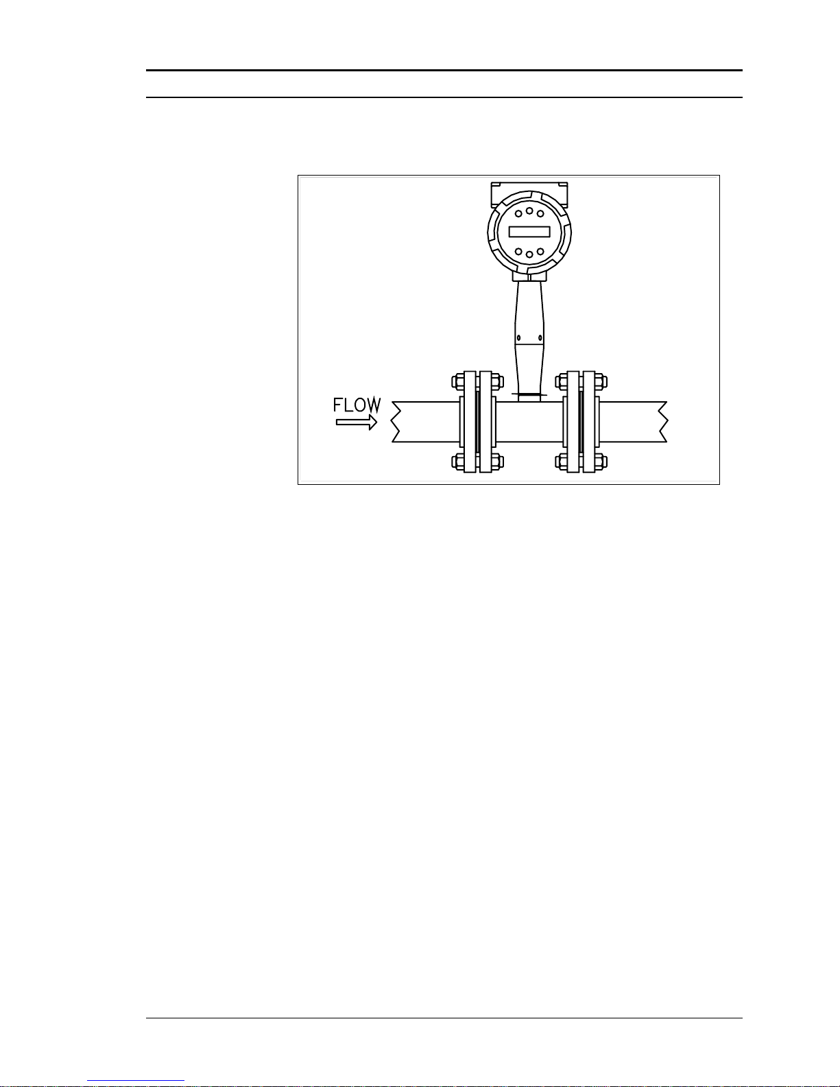
Figure 1-1. In-Line Vortex Multi-Parameter Mass Flow Meter
VorTek Series M22, M23, and M24 Pro-V™ Multi-Parameter Vortex
Mass Flow Meters use a unique sensor head to monitor mass flow rate by
directly measuring three variables–fluid velocity, temperature and pres-
sure. The built-in flow computer calculates the mass flow rate and volu-
metric flow rate based on these three direct measurements. The velocity,
temperature and pressure sensing head is built into the vortex meter’s
flow body. To measure fluid velocity, the flow meter incorporates a bluff
body (shedder bar) in the flow stream and measures the frequency of vor-
tices created by the shedder bar. Temperature is measured using a plati-
num resistance temperature detector (PRTD). Pressure measurement is
achieved using a solid-state pressure transducer. All three elements are
combined into an integrated sensor head assembly located downstream
of the shedder bar within the flow body.
Velocity Measurement
The Pro-V vortex velocity sensor is a patented mechanical design that
minimizes the effects of pipeline vibration and pump noise, both of which
are common error sources in flow measurement with vortex flow meters.
The velocity measurement is based on the well-known Von Karman vor-
tex shedding phenomenon. Vortices are shed from a shedder bar, and the
vortex velocity sensor located downstream of the shedder bar senses the
passage of these vortices. This method of velocity measurement has many
advantages including inherent linearity, high turndown, reliability and
simplicity.
Page 14
Chapter 1 Introduction Series M22/M23 Instruction Manual
1-4 M-000-00010
Vortex Shedding Frequency
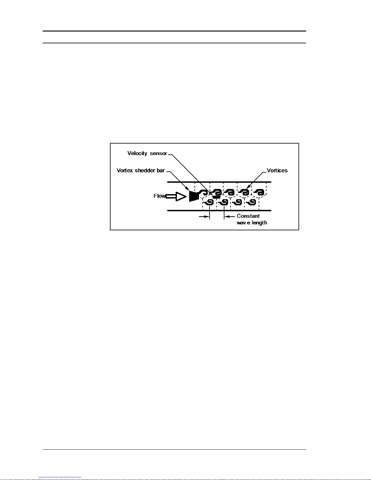
Von Karman vortices form downstream of a shedder bar into two distinct
wakes. The vortices of one wake rotate clockwise while those of the other wake rotate counterclockwise. Vortices generate one at a time, alternating from the left side to the right side of the shedder bar. Vortices interact with their surrounding space by over-powering every other nearby
swirl on the verge of development. Close to the shedder bar, the distance
(or wave length) between vortices is always constant and measurable.
Therefore, the volume encompassed by each vortex remains constant, as
shown below. By sensing the number of vortices passing by the velocity
sensor, the Pro-V™ Flow Meter computes the total fluid volume.
Figure 1-2. Measurement Principle of Vortex Flow Meters
Vortex Frequency Sensing
The velocity sensor incorporates a piezoelectric element that senses the
vortex frequency. This element detects the alternating lift forces produced by the Von Karman vortices flowing downstream of the vortex
shedder bar. The alternating electric charge generated by the piezoelectric element is processed by the transmitter’s electronic circuit to obtain
the vortex shedding frequency. The piezoelectric element is highly sensitive and operates over a wide range of flows, pressures and temperatures.
Page 15
Series M22/M23/M24 Instruction Manual Chapter 1 Introduction
M-000-00010 1-5
Re =
V D
Flow Velocity Range
To ensure trouble-free operation, vortex flow meters must be correctly
sized so that the flow velocity range through the meter lies within the
measurable velocity range (with acceptable pressure drop) and the linear
range.
The measurable range is defined by the minimum and maximum velocity
using the following table.
Gas
Liquid
Vmin
25
ft/s
1 ft/s
English (lb/ft3)
Vmax
0.5 in
0.75 in
1 in
1.5 in and
greater
175 ft/s
250 ft/s
250 ft/s
300 ft/s
30 ft/s
30 ft/s
30 ft/s
30 ft/s
Vmin
37
m/s
0.3 m/s
Metric (kg/m3)
Vmax
DN15
DN20
DN25
DN40 and
greater
53 m/s
76 m/s
76 m/s
91 m/s
9.1 m/s
9.1 m/s
9.1 m/s
9.1 m/s
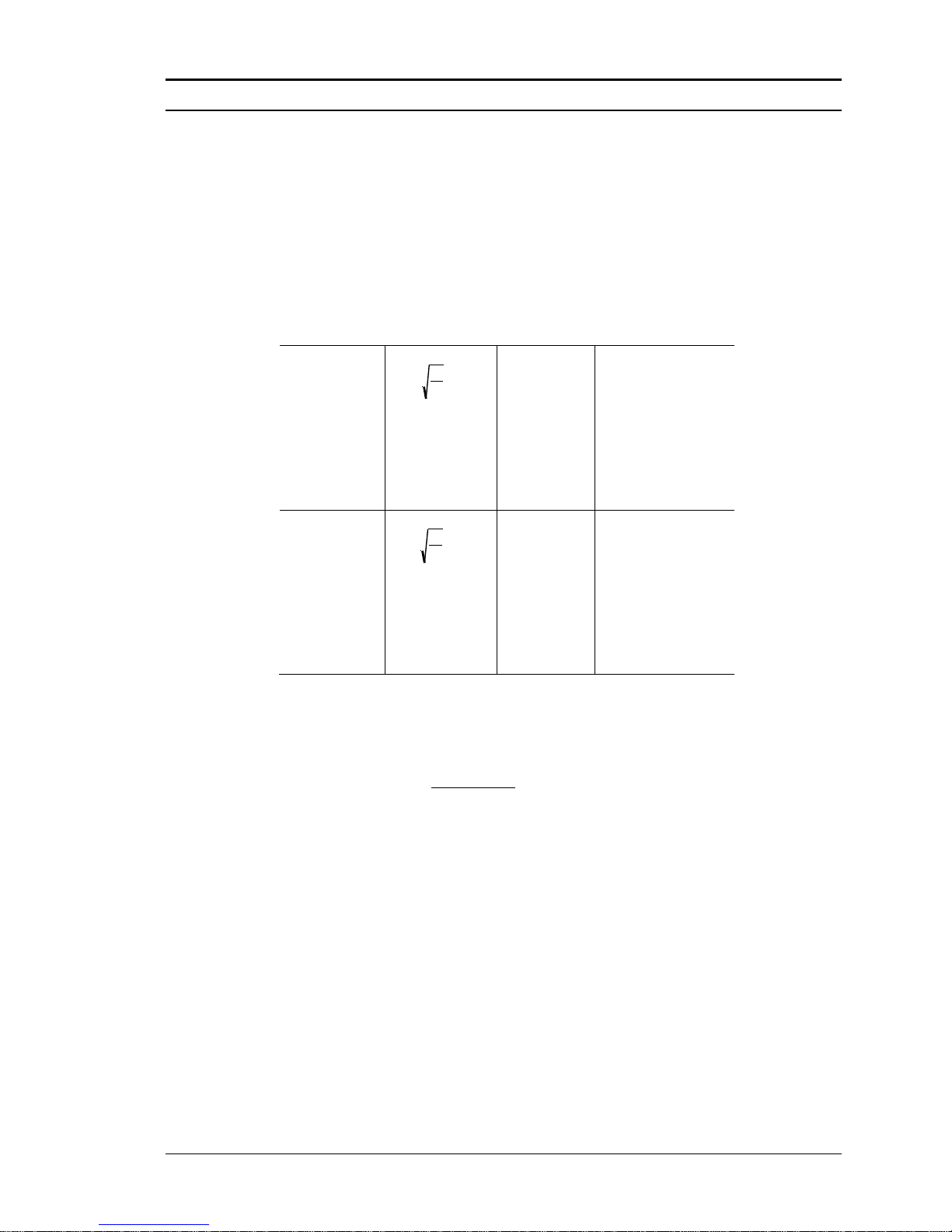
The linear range is defined by the Reynolds number. The Reynolds number is the
ratio of the inertial forces to the viscous forces in a flowing fluid and is defined
as:
Where
Re = Reynolds Number
= mass density of the fluid being measured
V = velocity of the fluid being measured
D = internal diameter of the flow channel
= viscosity of the fluid being measured
Page 16
Chapter 1 Introduction Series M22/M23 Instruction Manual
1-6 M-000-00010
The Strouhal number is the other dimensionless number that quantifies the vortex
phenomenon. The Strouhal number is defined as:
St = f d
V
Where
St = Strouhal Number
f = frequency of vortex shedding
d = shedder bar width
V = fluid velocity
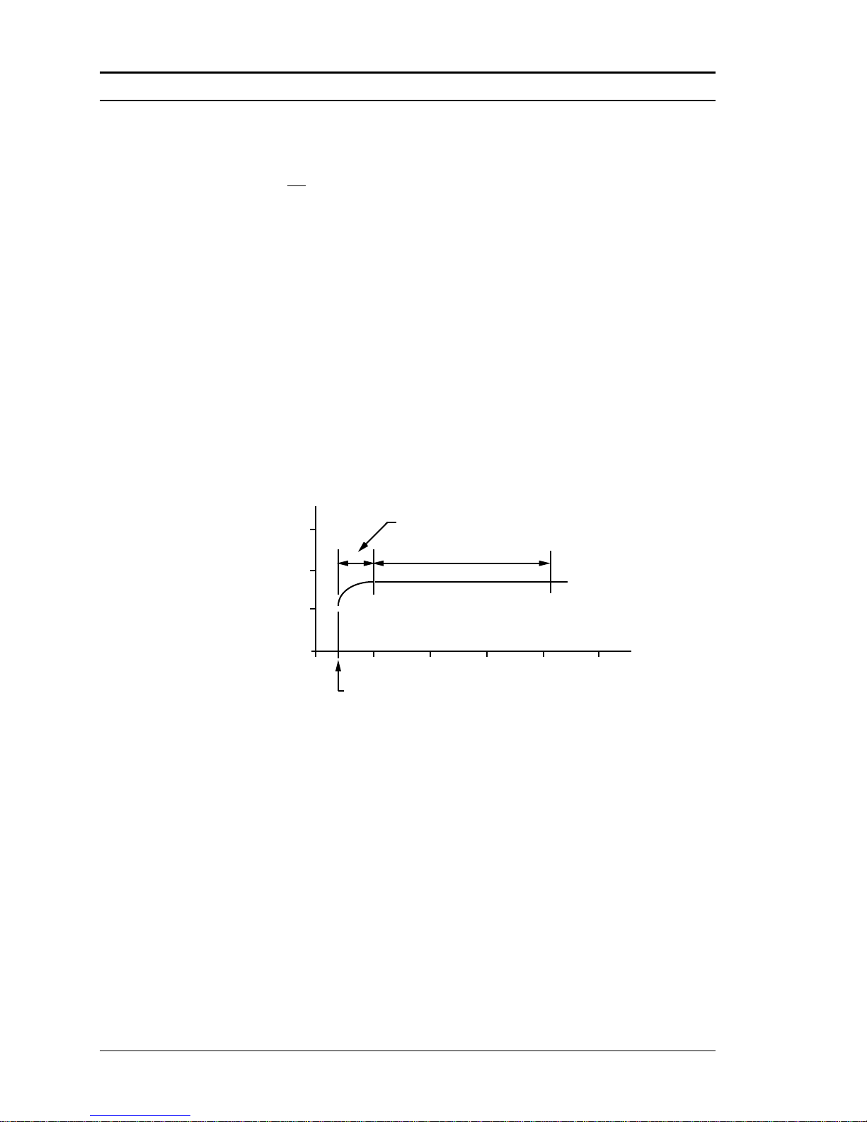
As shown in Figure 1-3, Pro-V™ meters exhibit a constant Strouhal number
across a large range of Reynolds numbers, indicating a consistent linear output
over a wide range of flows and fluid types. Below this linear range, the intelligent
electronics in Pro-V automatically corrects for the variation in the Strouhal num-
ber with the Reynolds number. The meter’s smart electronics corrects for this
non-linearity via its simultaneous measurements of the process fluid temperature
and pressure. This data is then used to calculate the Reynolds number in real
time. Pro-V meters automatically correct down to a Reynolds number of 5,000.
Figure 1-3. Reynolds Number Range for the Pro-V
Pressure Drop
The pressure drop for series M23 insertion meters is negligible. The pressure drop
for series M22/M24 in-line meters is defined as:
P = .00024 V
2
English units (P in psi, in lb/ft3, V in ft/sec)
P = .000011 V
2
Metric units (P in bar, in kg/m3, V in m/sec)
Minimum Back Pressure
A minimum back pressure is required to prevent cavitation in the vortex
flow meter when installed in liquid applications. Cavitation is a phenomenon wherein a liquid passing through a low pressure zone no longer can
remain in the liquid phase and therefore partially flashes (or “boils”) into
0.3
0.2
0.1
0.0
3 4
10
Linear range
Rey nolds Number, Re
Strouhal Number, St
10
5
10 10
8
10
6
10
7
5000
Corrected range
Page 17

Series M22/M23/M24 Instruction Manual Chapter 1 Introduction
M-000-00010 1-7
its vapor phase. The resulting two-phase flow degrades the liquid calibration accuracy. For some applications, a valve downstream of the flow meter may be required to increase the pressure in the meter, thereby avoiding
cavitation. The following equation defines the minimum back pressure to
prevent cavitation.
P = 2.9 P + 1.3 P
V
Where:
P = Minimum line pressure five pipe diameters downstream of the flow
meter required to avoid cavitation (psia or bara).
P = Permanent pressure loss across the flow meter (psia or bara).
PV = Liquid vapor pressure at actual flowing conditions (psia or bara).
Temperature Measurement
Pro-V Flow Meters use a 1000 ohm platinum resistance temperature detec-
tor (PRTD) to measure fluid temperature.
Pressure Measurement
Pro-V Flow Meters incorporate a solid-state pressure transducer isolated
by a 316 stainless steel diaphragm. The transducer itself is micro-
machined silicon, fabricated using integrated circuit processing technol-
ogy. A nine-point pressure/temperature calibration is performed on every
sensor. Digital compensation allows these transducers to operate within a
0.3% of full scale accuracy band within the entire ambient temperature
range of -40°F to 140°F (-40 to 60°C). Thermal isolation of the pressure
transducer ensures the same accuracy across the allowable process fluid
temperature range of -330°F to 750°F (-200 to 400°C).
Page 18

Chapter 1 Introduction Series M22/M23 Instruction Manual
1-8 M-000-00010
Flow Meter Configurations
Pro-V™ Vortex Mass Flow Meters are available in two model
configurations:
• Series M22/M24 in-line flow meter (replaces a section of the pipeline)
• Series M23 insertion flow meter (requires a “cold” tap or a “hot”
tap into an existing pipeline)
Both the in-line and insertion configurations are similar in that they both
use identical electronics and have similar sensor heads. Besides installation differences, the main difference between an in-line flow meter and
an insertion flow meter is their method of measurement.
For an in-line vortex flow meter, the shedder bar is located across the entire diameter of the flow body. Thus, the entire pipeline flow is included
in the vortex formation and measurement. The sensing head, which directly measures velocity, temperature and pressure is located just downstream of the shedder bar.
Insertion vortex flow meters have a shedder bar located across the diameter of a short tube. The velocity, temperature and pressure sensor are
located within this tube just downstream of a built-in shedder bar. This
entire assembly is called the insertion sensing head. It fits through any
entry port with a 1.875 inch minimum internal diameter.
The sensing head of an insertion vortex flow meter directly monitors the
velocity at a point in the cross-sectional area of a pipe, duct, or stack (re-
ferred to as “channels”). The velocity at a point in the pipe varies as a func-
tion of the Reynolds number. The insertion vortex flow meter computes the
Reynolds number and then computes the total flow rate in the channel. The
output signal of insertion meters is the total flow rate in the channel. The
accuracy of the total flow rate computation depends on adherence to the
piping installation requirements given in Chapter 2. If adherence to those
guidelines cannot be met, contact the factory for specific installation advice.
Multivariable Options
The M22, M23, or M24 models are available with the following options:
V, volumetric flowmeter; VT, velocity and temperature sensors; VTP,
velocity, temperature, and pressure sensors; VT-EM energy output options; VTP-EM, energy options with pressure; VT-EP, external pressure
transmitter input; VETEP, external RTD temperature input, external 4-20
mA input.
Page 19

Series M22/M23/M24 Instruction Manual Chapter 1 Introduction
M-000-00010 1-9
Line Size / Process Connections / Materials
The M22/M24 In-line model is built for line sizes ½ through 4 inch wa-
fer or ½ through 12 inch flanged design using ANSI 150, 300, 600,
PN16, 40, or 64 class flanges. JIS flanges available upon request.
The M23 Insertion model can be used in line sizes 2 inch and greater and
is built with a compression fitting or packing gland design using 2 inch
NPT, or 2 inch flanged connections (ANSI 150, 300, 600, PN16, 40, or
64 class flanges). The packing gland design can be ordered with a per-
manent or removable retractor.
The M22/M24 In-line model can be built with A105 carbon steel, 316L
stainless steel, or Hastelloy C-276. The M23 Insertion model can be
built with 316L stainless steel or Hastelloy C-276.
Flow Meter Electronics
Pro-V Flow Meter electronics are available mounted directly to the flow
body, or remotely mounted. The electronics housing may be used indoors
or outdoors, including wet environments. Available input power options
are: DC loop powered (2-wire), DC powered, or AC powered. Three an-
alog output signals are available for your choice of three of the five pro-
cess variables: mass flow rate, volumetric flow rate, temperature, pres-
sure or fluid density. A pulse output signal for remote totalization and
MODBUS, HART, and BACnet communications are also available.
Pro-V Flow Meters include a local 2 x 16 character LCD display housed
within the enclosure. Local operation and reconfiguration is accom-
plished using six pushbuttons operated via finger touch. For hazardous
locations, the six buttons can be operated with the electronics enclosure
sealed using a hand-held magnet, thereby not compromising the integrity
of the hazardous location certification.
The electronics include nonvolatile memory that stores all configuration
information. The nonvolatile memory allows the flow meter to function
immediately upon power up, or after an interruption in power. All
flowmeters are calibrated and configured for the customer’s flow
application.
Page 20

Chapter 1 Introduction Series M22/M23/M24 Instruction Manual
1-10 M-000-00010
Page 21

Series M22/M23/M24 Instruction Manual Chapter 2 Installation
M-000-00010 2-1
Chapter 2 Installation
Installation Overview
VorTek’s Pro-V Vortex Flow Meter installations are simple and straight-
forward. Both the Series M22/M24 In-Line and Series M23 Insertion type
flow meter installations are covered in this chapter. After reviewing the
installation requirements given below, see page 2-3 for Series M22/M24
installation instructions. See page 2-6 for Series M23 installation instruc-
tions. Wiring instructions begin on page 2-20.
Flow Meter Installation Requirements
Before installing the flow meter, verify the installation site allows for
these considerations:
1. Line pressure and temperature will not exceed the flow meter
rating.
2. The location meets the required minimum number of pipe di-
ameters upstream and downstream of the sensor head as illustrated in Figure 2-1.
3. Safe and convenient access with adequate overhead clear-
ance for maintenance purposes.
4. Verify that the cable entry into the instrument meets the
specific standard required for hazardous area installations.
The cable entry device shall be of a certified flameproof
type, suitable for the conditions of use and correctly installed. The degree of protection of at least IP66 to EN
60529 is only achieved if certified cable entries are used
that are suitable for the application and correctly installed.
Unused apertures shall be closed with suitable blanking elements.
5. For remote installations, verify the supplied cable length is
sufficient to connect the flow meter sensor to the remote
electronics.
Also, before installation check your flow system for anomalies such as:
• leaks
• valves or restrictions in the flow path that could create disturb-
ances in the flow profile that might cause unexpected flow rate indications
Warning!
Consult the flow meter nameplate for
specific flow meter approvals before any
hazardous location installation.
Page 22
Chapter 2 Installation Series M22/M23/M24 Instruction Manual
2-2 M-000-00010
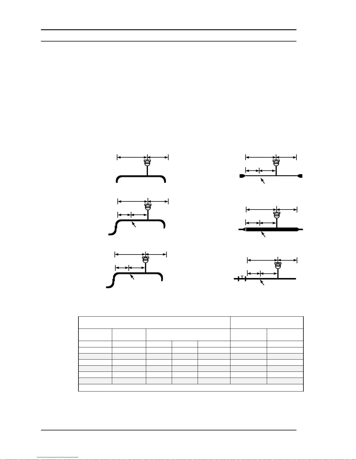
Unobstructed Flow Requirements
Select an installation site that will minimize possible distortion in the flow
profile. Valves, elbows, control valves and other piping components may
cause flow disturbances. Check your specific piping condition against the
examples shown below. In order to achieve accurate and repeatable performance install the flow meter using the recommended number of
straight run pipe diameters upstream and downstream of the sensor.
Note: For liquid applications in vertical pipes, avoid installing with flow
in the downward direction because the pipe may not be full at all points.
Choose to install the meter with flow in the upward direction if possible.
Minimum Required
Upstream Diameters
Minimum Required
Downstream Diameters
No Flow
Conditioner
With Flow Conditioner
No Flow
Conditioner
With Flow
Conditioner
Example
A A C
C´ B B 1 10 D
N/A
N/A
N/A
5 D
5 D
2
15 D
10 D
5 D
5 D
5 D
5 D
3
30 D
10 D
5 D
5 D
10 D
5 D
4
10 D
10 D
5 D
5 D
5 D
5 D
5
20 D
10 D
5 D
5 D
5 D
5 D
6
30 D
10 D
5 D
5 D
10 D
5 D
D = Internal diameter of channel. N/A = Not applicable
Figure 2-1. Recommended Pipe Length Requirements for Installation, Series M22/M23/M24
Flow meter
A B
Example 1.
One 90° elbow before meter
C'
Flow meter
A B
C
Flow conditioner
(if used)
Example 2.
Two 90° elbows before meter in one plane
C'
Flow meter
A B
C
Flow conditioner
(if used)
Example 3.
Two 90° elbows before meter out of plane (if three
90° bends present, double recommended length)
Flow meter
A B
Example 4.
Reduction before meter
C' C
Flow conditioner
(if used)
Flow meter
A B
C' C
Flow conditioner
(if used)
Example 5.
Expansion before meter
Example 6.
Regulator or valve partially closed before meter
(If valve is always wide open, base length
requirements on fitting directly preceding it)
Flow meter
A B
C' C
Flow conditioner (if used)
Page 23
Series M22/M23/M24 Instruction Manual Chapter 2 Installation
M-000-00010 2-3
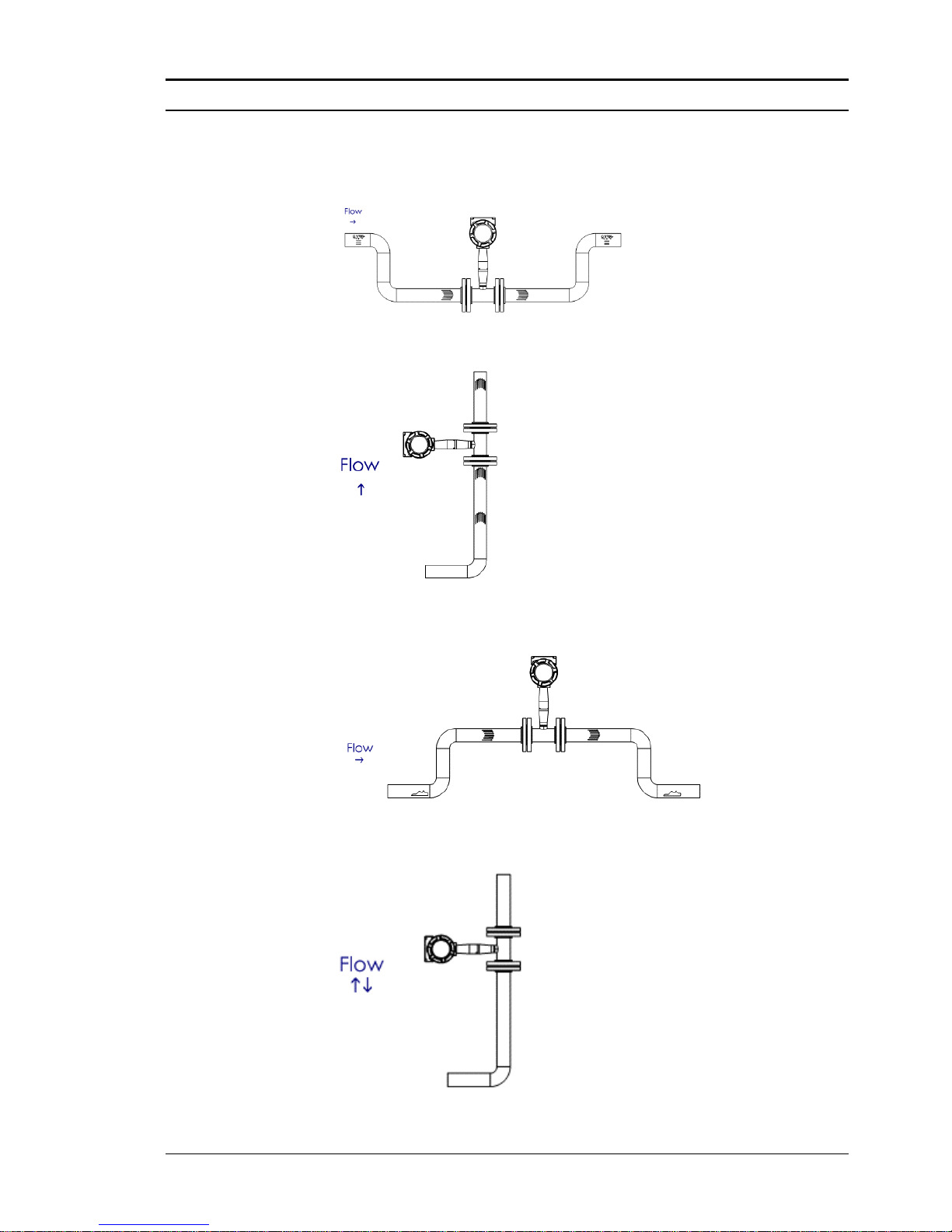
Recommended Meter Locations
Liquid Horizontal
Liquid Vertical
Gas or Steam Horizontal
Gas or Steam Vertical
Page 24
Chapter 2 Installation Series M22/M23/M24 Instruction Manual
2-4 M-000-00010
Series M22/M24 In-Line Flow Meter Installation
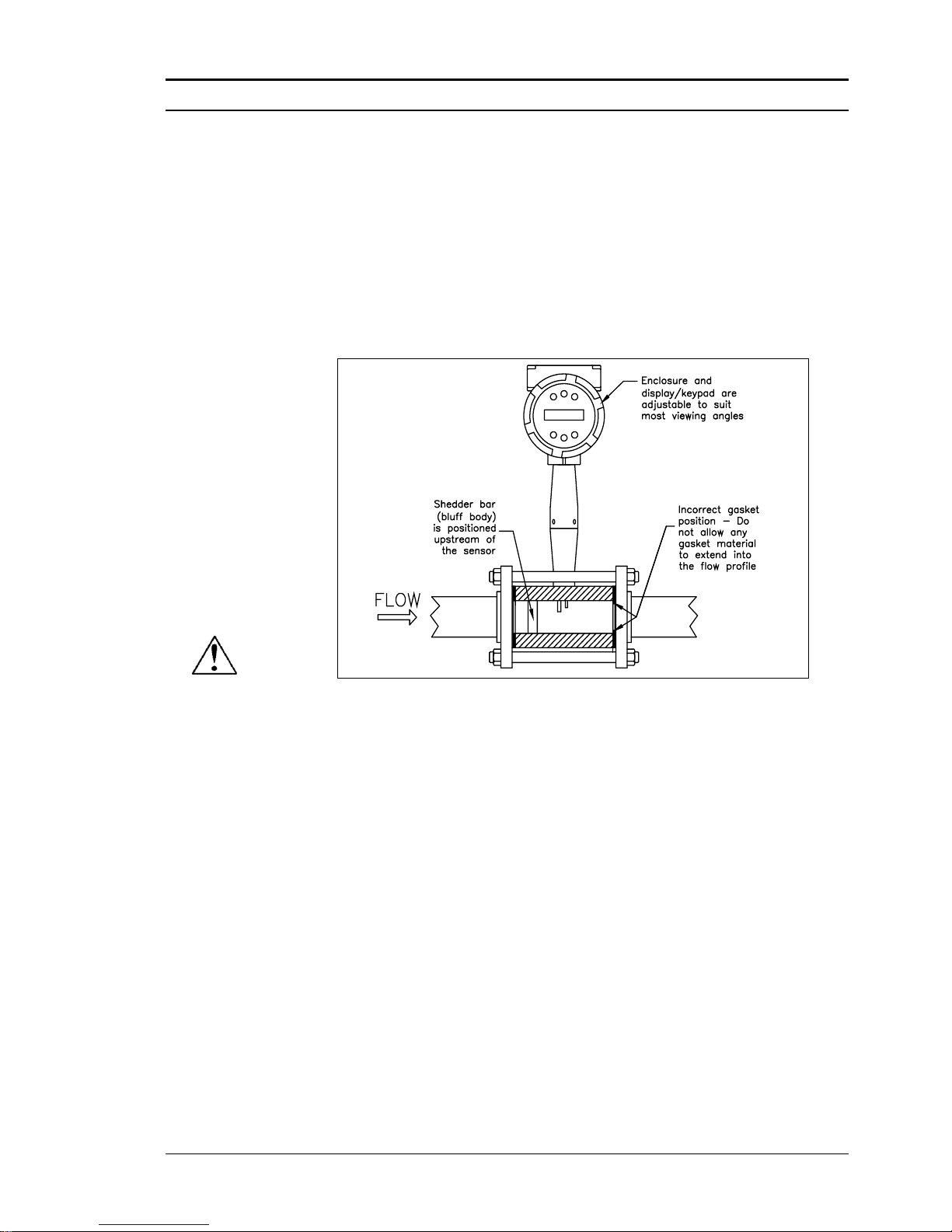
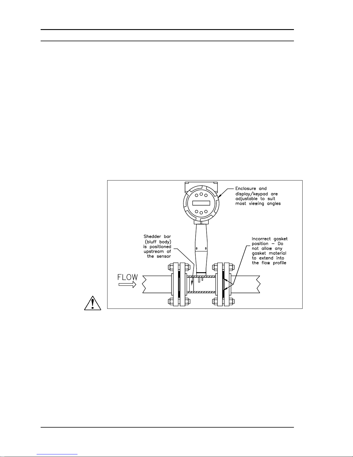
Install the Series M22/M24 In-Line Flow Meter between two conventional pipe flanges as shown in Figures 2-3 and 2-4.
The meter inside diameter is equal to the same size nominal pipe ID in
schedule 80. For example, a 2” meter has an ID of 1.939” (2” schedule
80). Do not install the meter in a pipe with an inside diameter smaller
than the inside diameter of the meter. For schedule 160 and higher
pipe, a special meter is required. Consult the factory before purchasing
the meter.
Series M22/M24 Meters require customer-supplied gaskets. When selecting gasket material make sure that it is compatible with the process fluid
and pressure ratings of the specific installation. Verify that the inside diameter of the gasket is larger than the inside diameter of the flow meter
and adjacent piping. If the gasket material extends into the flow stream, it
will disturb the flow and cause inaccurate measurements.
Flange Bolt Specifications
Stud bolt lengths may be calculated using the following equation:
L = Meter face to face length + 2 (mounting flange thickness + flange
raised face) + 2 (gasket thickness) + 4 (mounting nut thickness)
Refer to the mounting flange specification to select the correct stud
bolt diameter.
The required bolt load for sealing the gasket joint is affected by several
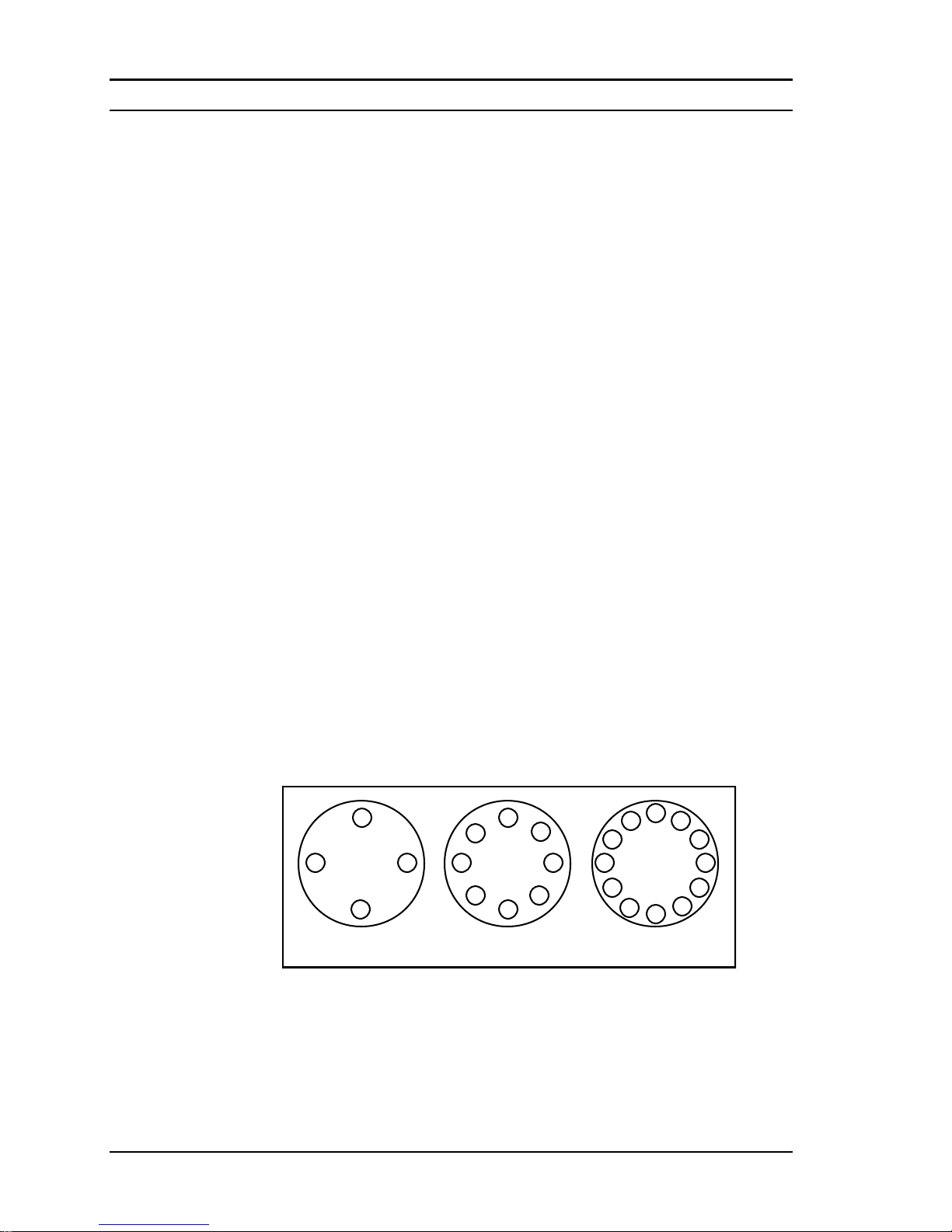
application-dependent factors; therefore the required torque for each application may be different. Refer to the ASME Pressure Vessel Code
guidelines for bolt tightening standards.
Figure 2-2. Flange Bolt Torquing Sequence
1
2
34
1
2
34
5
6
7
8
1
5
9
3
7
11
2
6
10
4
8
12
4-bolt 8-bolt 12-bolt
Page 25
Series M22/M23/M24 Instruction Manual Chapter 2 Installation
M-000-00010 2-5
Wafer-Style Flow Meter Installation
Install the wafer-style meter between two conventional pipe flanges of the
same nominal size as the flow meter. If the process fluid is a liquid, make
sure the meter is located where the pipe is always full. This may require
locating the meter at a low point in the piping system. Note: Vortex flow
meters are not suitable for two-phase flows (i.e., liquid and gas mixtures).
For horizontal pipelines having a process temperature above 300° F,
mount the meter at a 45 or 90-degree angle to avoid overheating the elec-
tronics enclosure. To adjust the viewing angle of the enclosure or dis-
play/keypad, see page 2-18 and 2-19.
Figure 2-3. Wafer-Style Flow Meter Installation
When installing the meter make sure the section marked with a flow arrow is
positioned upstream of the outlet, with the arrow head pointing in the direc-
tion of flow. (The mark is on the wafer adjacent to the enclosure mounting
neck.) This ensures that the sensor head is positioned downstream of the vor-
tex shedder bar and is correctly aligned to the flow. Installing the meter oppo-
site this direction will result in completely inaccurate flow measurement. To
install the meter:
1. Turn off the flow of process gas, liquid or steam. Verify that the line
is not pressurized. Confirm that the installation site meets the required
minimum upstream and downstream pipe diameters.
2. Insert the studs for the bottom side of the meter body between the pipe
flanges. Place the wafer-style meter body between the flanges with the
end stamped with a flow arrow on the upstream side, with the arrow
head pointing in the direction of flow. Center the meter body inside the
diameter with respect to the inside diameter of the adjoining piping.
3. Position the gasket material between the mating surfaces. Make sure
both gaskets are smooth and even with no gasket material extending into the flow profile. Obstructions in the pipeline will disturb the flow and
cause inaccurate measurements.
Caution!
When using toxic or corrosive
gases, purge the line with inert
gas for a minimum of four hours
at full gas flow before installing
the flow meter.
Page 26
Chapter 2 Installation Series M22/M23/M24 Instruction Manual
2-6 M-000-00010
4. Place the remaining studs between the pipe flanges. Tighten the nuts in
the sequence shown in Figure 2-2. Check for leaks after tightening the
flange bolts
Flange-Style Flow Meter Installation
Install the flange-style meter between two conventional pipe flanges of
the same nominal size as the flow meter. If the process fluid is a liquid,
make sure the meter is located where the pipe is always full. This may require locating the meter at a low point in the piping system. Note: Vortex
flow meters are not suitable for two-phase flows (i.e., liquid and gas mixtures). For horizontal pipelines having a process temperature above 300°
F, mount the meter at a 45 or 90-degree angle to avoid overheating the
electronics enclosure. To adjust the viewing angle of the enclosure or display/keypad, see page 2-18 and 2-19.
Figure 2-4. Flange-Style Flow Meter Installation
When installing the meter make sure the flange marked with a flow arrow is
positioned upstream of the outlet flange, with the arrow head pointing in the
direction of flow. (The mark is on the flange adjacent to the enclosure
mounting neck.) This ensures that the sensor head is positioned downstream
of the vortex shedder bar and is correctly aligned to the flow. Installing the
meter opposite this direction will result in completely inaccurate flow measurement. To install the meter:
1. Turn off the flow of process gas, liquid or steam. Verify that the line
is not pressurized. Confirm that the installation site meets the required
minimum upstream and downstream pipe diameters.
Caution!
When using toxic or corrosive
gases, purge the line with inert
gas for a minimum of four hours
at full gas flow before installing
the flow meter.
Page 27
Series M22/M23/M24 Instruction Manual Chapter 2 Installation
M-000-00010 2-7
2. Seat the meter level and square on the mating connections with the flange
stamped with a flow arrow on the upstream side, with the arrow head
pointing in the direction of flow. Position a gasket in place for each side.
Make sure both gaskets are smooth and even with no gasket material extending into the flow profile. Obstructions in the pipeline will disturb the
flow and cause inaccurate measurements.
3. Install bolts in both process connections. Tighten the nuts in the se-
quence shown in Figure 2-2. Check for leaks after tightening the flange
bolts.
Series M23 Insertion Flow Meter Installation
Prepare the pipeline for installation using either a cold tap or hot tap
method described on the following pages. Refer to a standard code for all
pipe tapping operations. The following tapping instructions are general in
nature and intended for guideline purposes only. Before installing the meter, review the mounting position and isolation value requirements given
below.
Mounting Position
Allow clearance between the electronics enclosure top and any other obstruction when the meter is fully retracted.
Isolation Valve Selection
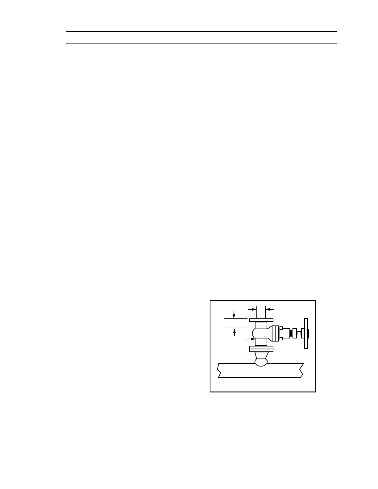
An isolation valve is available as an option with Series M23 meters. If
you supply the isolation valve, it must meet the following requirements:
1. A minimum valve
bore diameter of
1.875 inches is required, and the
valve’s body size
should be two inches.
Normally, gate
valves are used.
2. Verify that the
valve’s body and
flange rating are
within the flow meter’s maximum operating pressure and temperature.
3. Choose an isolation valve with at least two inches existing between
the flange face and the gate portion of the valve. This ensures that the
flow meter’s sensor head will not interfere with the operation of the
isolation valve.
1.875-inch min.
valve bore
2-inch min.
2-inch
valve size
Isolation Valve Requirements
Page 28
Chapter 2 Installation Series M22/M23/M24 Instruction Manual
2-8 M-000-00010
Cold Tap Guidelines
Refer to a standard code for all pipe tapping operations. The following
tapping instructions are general in nature and intended for guideline purposes only.
1. Turn off the flow of process gas, liquid or steam. Verify that the line
is not pressurized.
2. Confirm that the installation site meets the minimum upstream and
downstream pipe diameter requirements. See Figure 2-1.
3. Use a cutting torch or sharp cutting tool to tap into the pipe. The pipe
opening must be at least 1.875 inches in diameter. (Do not attempt to
insert the sensor probe through a smaller hole.)
4. Remove all burrs from the tap. Rough edges may cause flow profile
distortions that could affect flow meter accuracy. Also, obstructions
could damage the sensor assembly when inserting into the pipe.
5. After cutting, measure the thickness of the cut-out and record this
number for calculating the insertion depth.
6. Weld the flow meter pipe connection
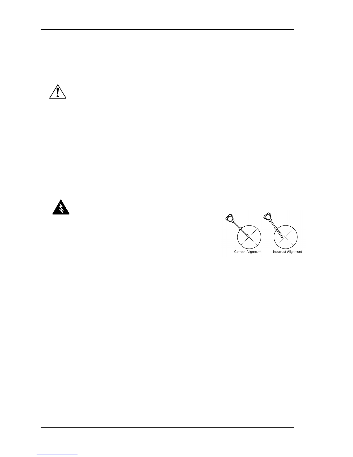
on the pipe. Make sure this connection
is within ± 5° perpendicular to the pipe
centerline.
7. Install the isolation valve (if used).
8. When welding is complete and all fittings are installed, close the
isolation valve or cap the line. Run a static pressure check on the
welds. If pressure loss or leaks are detected, repair the joint and retest.
9. Connect the meter to the pipe process connection.
10. Calculate the sensor probe insertion depth and insert the sensor probe
into the pipe as described on the following pages.
Caution!
When using toxic or
corrosive gases, purge
the line with inert gas
for a minimum of four
hours at full gas flow
before installing the
flow meter.
Warning!
All flow meter connec-
tions, isolation valves
and fittings for cold tap-
ping must have the same
or higher pressure rating
as the main pipeline.
Page 29

Series M22/M23/M24 Instruction Manual Chapter 2 Installation
M-000-00010 2-9
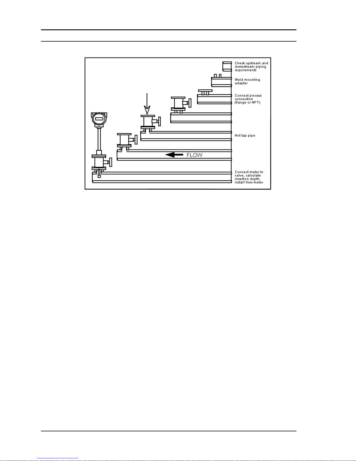
Hot Tap Guidelines
Refer to a standard code for all pipe tapping operations. The following
tapping instructions are general in nature and intended for guideline purposes only.
1. Confirm that the installation site meets the minimum upstream and
downstream pipe diameter requirements.
2. Weld a two inch mounting adapter on the pipe. Make sure the mount-
ing adapter is within ± 5° perpendicular to the pipe centerline (see
previous page). The pipe opening must be at least 1.875 inches in diameter.
3. Connect a two inch process connection on the mounting adapter.
4. Connect an isolation valve on the process connection. The valve’s full
open bore must be at least 1.875 inches in diameter.
5. Run a static pressure check on the welds. If pressure loss or leaks are
detected, repair the joint and re-test.
6. Connect the hot tapping equipment to the isolation valve, open the
isolation valve and drill at least a 1.875 inch diameter hole.
7. Retract the drill, close the isolation valve, and remove the hot tapping
equipment.
8. Connect the flow meter to the isolation valve and open the isolation
valve.
9. Calculate the sensor probe insertion depth and insert the sensor probe
into the pipe as described on the following pages.
Warning!
Hot tapping must be
performed by a trained
professional. US. regulations
often require a hot tap permit.
The manufacturer of the hot
tap equipment and/or the
contractor performing the hot
tap is responsible for provid-
ing proof of such a permit.
Warning!
All flow meter connections,
isolation valves, and fittings
for hot tapping must have the
same or higher pressure
rating as the main pipeline.
Page 30
Chapter 2 Installation Series M22/M23/M24 Instruction Manual
2-10 M-000-00010
Connect isolation
valve and test for
leaks
xxxxxxxxxxxxxxxxxxxx
xxxxxxxxxxxxxxxxxxxx
xxxxxxxxxxxxxxxxxxxx
xxxxxxxxxxxxxxxxxxxx
Purge pipe
Figure 2-5. Hot Tap Sequence
Page 31

Series M22/M23/M24 Instruction Manual Chapter 2 Installation
M-000-00010 2-11
Flow Meter Insertion
The sensor head must be properly positioned in the pipe. For this reason,
it is important that insertion length calculations are carefully followed. A
sensor probe inserted at the wrong depth in the pipe will result in inaccurate readings.
Insertion flow meters are applicable to pipes 2 inch and larger. For pipe
sizes ten inches and smaller, the centerline of the meter’s sensing head is
located at the pipe’s centerline. For pipe sizes larger than ten inches, the
centerline of the sensing head is located in the pipe’s cross section five
inches from the inner wall of the pipe; i.e., its “wetted” depth from the
wall to the centerline of the sensing head is five inches.
Insertion flow meters are available in three probe lengths:
Standard Probe configuration is used with most flow meter process
connections. The length, S, of the stem is 29.47 inches.
Compact Probe configuration is used with compression fitting process
connections. The length, S, of the stem is 13.1 inches.
12-Inch Extended Probe configuration is used with exceptionally lengthy
flow meter process connections. The length, S, of the stem is 41.47 inches.
Use the Correct Insertion Formula
Depending on your flow meter’s process connection, use the applicable
insertion length formula and installation procedure as follows:
• Flow meters with a compression type connection (NPT or flanged)
follow the instructions beginning on page 2-11.
• Flow meters with a packing gland type connection (NPT or flanged)
configured with an insertion tool, follow the instructions beginning on
page 2-13.
• Flow meters with a packing gland type connection (NPT or flanged)
without an insertion tool, follow the instructions beginning on page
2-16.
Warning!
An insertion tool must be
used for any installation
where a flow meter is
inserted under pressure
greater than 50 psig.
Page 32
Chapter 2 Installation Series M22/M23/M24 Instruction Manual
2-12 M-000-00010
Installing Flow Meters with a Compression Connection*
Use the following formula to determine insertion length for flow meters
(NPT and flanged) with a compression process connection. The installation procedure is given on the next page.
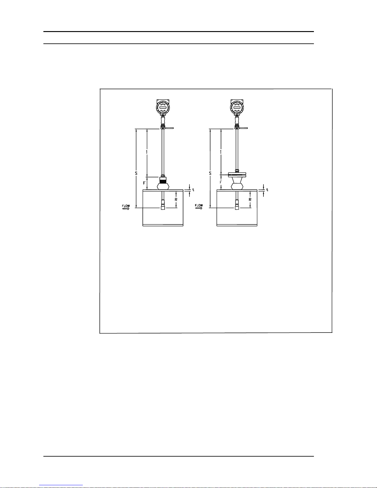
Insertion Length Formula
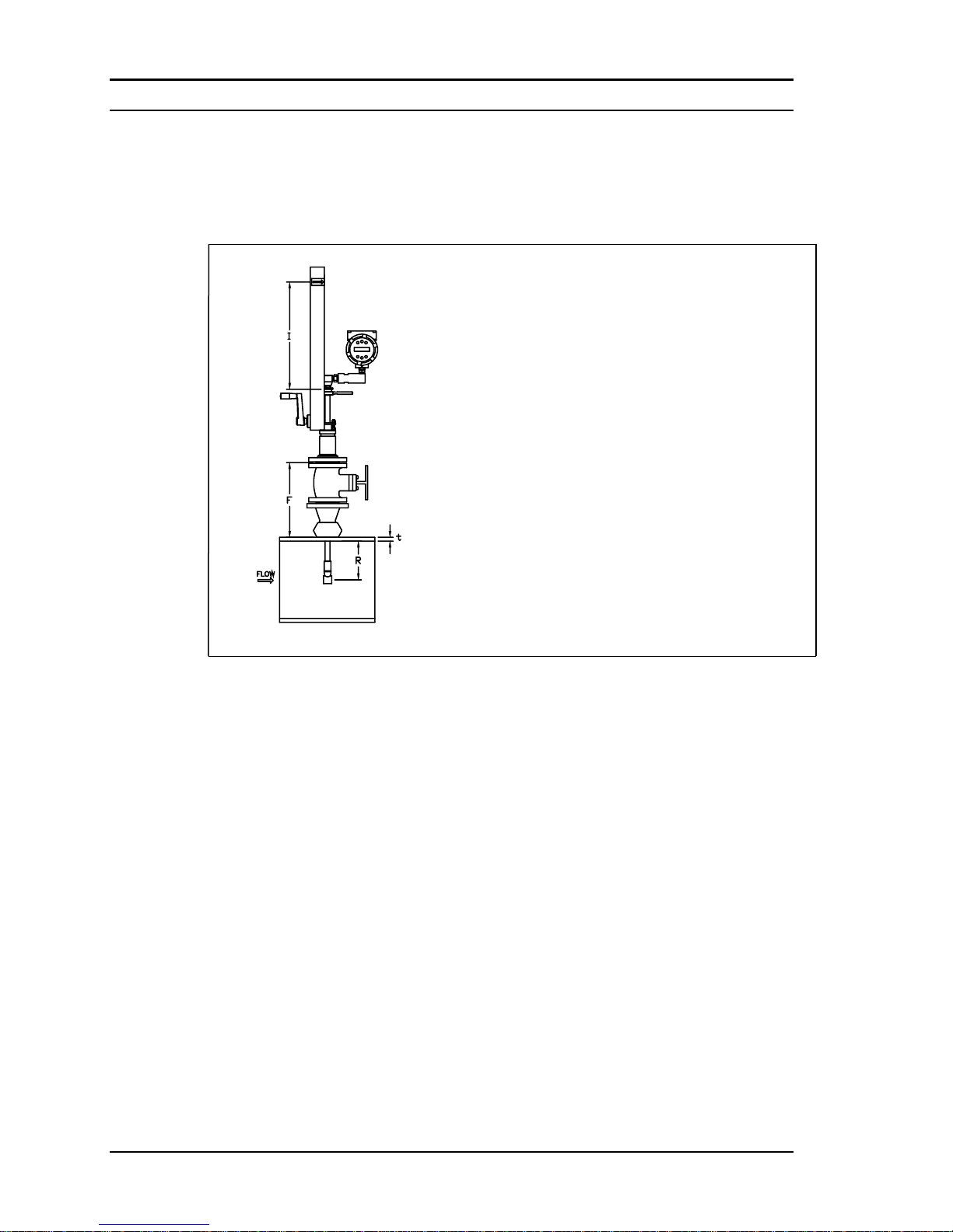
I = S – F – R – t
Where:
I = Insertion length.
S = Stem length – the distance from the center of the sensor head to the base
of the enclosure adapter (S = 29.47 inches for standard probes; S = 13.1
inches for compact; S = 41.47 inches for 12-inch extended).
F = Distance from the raised face of the flange or top of NPT stem housing to
the outside of the pipe wall.
R = Pipe inside diameter 2 for pipes ten inches and smaller.
R = Five inches for pipe diameters larger than ten inches.
t = Thickness of the pipe wall. (Measure the disk cut-out from the tapping
procedure or check a piping handbook for thickness.)
Figure 2-6. Insertion Calculation (Compression Type)
Example:
To install a Series M23 meter with a standard probe (S = 29.47 inches) into a 14
inch schedule 40 pipe, the following measurements are taken:
F=3 inches
R=5 inches
t=0.438 inches
The insertion length for this example is 21.03 inches. Insert the stem through
the fitting until an insertion length of 21.03 inches is measured with a ruler.
*All dimensions are in inches
Page 33
Series M22/M23/M24 Instruction Manual Chapter 2 Installation
M-000-00010 2-13
Insertion Procedure for Meters with a Compression Connection
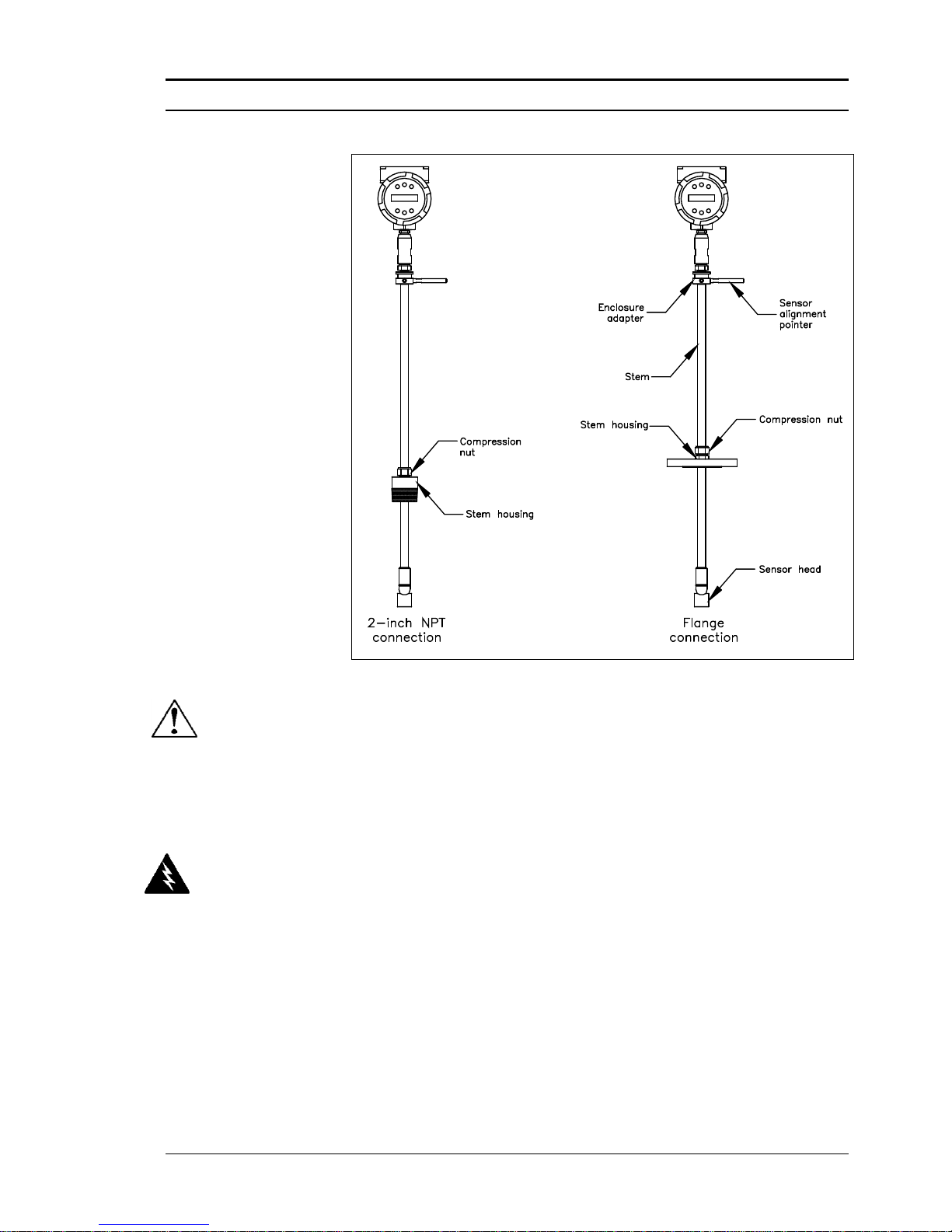
Figure 2-7. Flow Meter with Compression Type Fitting
1. Calculate the required sensor probe insertion length.
2. Fully retract the stem until the sensor head is touching the bottom of
the stem housing. Slightly tighten the compression nut to prevent
slippage.
3. Bolt or screw the flow meter assembly into the process connection.
Use Teflon tape or pipe sealant to improve the seal and prevent seizing on NPT styles.
4. Hold the meter securely while loosening the compression fitting. In-
sert the sensor into the pipe until the calculated insertion length, I, is
measured between the base of the enclosure adapter and the top of
the stem housing, or to the raised face of the flanged version. Do
not force the stem into the pipe.
5. Align the sensor head using the sensor alignment pointer. Adjust the
alignment pointer parallel to the pipe and pointing downstream.
6. Tighten the compression fitting to lock the stem in position. When
the compression fitting is tightened, the position is permanent.
Caution!
The sensor alignment
pointer must point
downstream, in the
direction of flow.
Warning!
To avoid serious injury,
DO NOT loosen the
compression fitting
under pressure.
Page 34
Chapter 2 Installation Series M22/M23/M24 Instruction Manual
2-14 M-000-00010
Installing Flow Meters with a Packing Gland Connection*
Use the formula below to determine the insertion depth for flow meters
(NPT and flanged) equipped with an insertion tool. To install, see the next
page for instructions for meters with a permanent insertion tool. For meters with a removable insertion tool, see page 2-15.
Insertion Length Formula
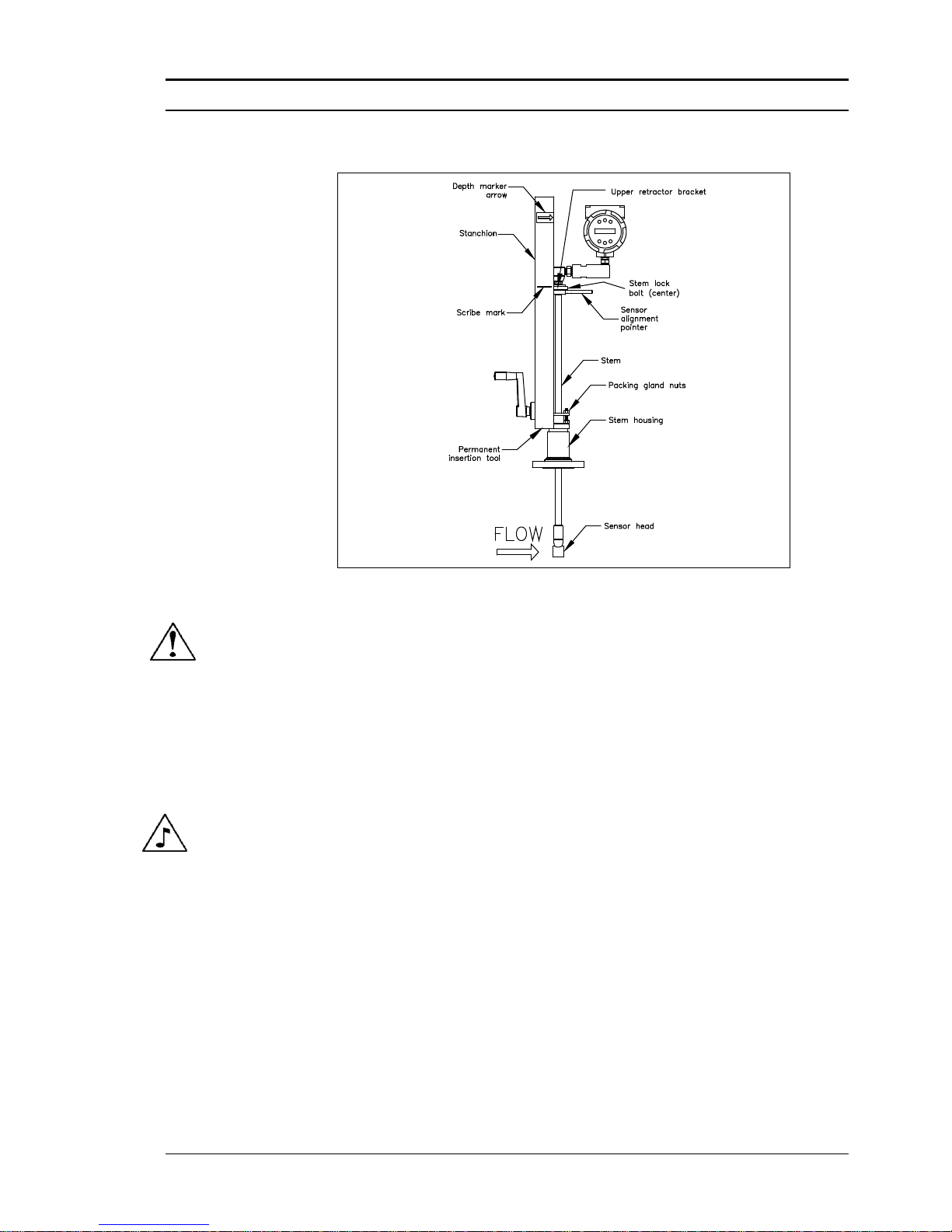
I = F + R + t – 1.35
Where:
I = Insertion length.
F = Distance from the raised face of the flange or top of
the process connection for NPT style meters to the top
outside of the process pipe.
R = Pipe inside diameter 2 for pipes ten inches & smaller.
R = Five inches for pipe diameters larger than ten inches.
t = Thickness of the pipe wall. (Measure the disk cutout from the tapping procedure or check a piping handbook for thickness.)
Figure 2-8. Insertion Calculation (Meters with Insertion Tool)
Example 1: Flange Style Meters:
To install a Series M23 Flow Meter into a 14 inch schedule 40 pipe, the following measurements are taken:
F = 12 inches
R = 5 inches
t = 0.438 inches
The example insertion length is 16.09 inches.
Example 2: NPT Style Meters:
The length of thread engagement on the NPT style meters is also subtracted in
the equation. The length of the threaded portion of the NPT meter is 1.18
inches. Measure the thread portion still showing after the installation and subtract that amount from 1.18 inches. This gives you the thread engagement
length. If this cannot be measured use .55 inch for this amount.
F = 12 inches
R = 5 inches
t = 0.438 inches
The example insertion length is 15.54 inches.
*All dimensions are in inches.
Page 35
Series M22/M23/M24 Instruction Manual Chapter 2 Installation
M-000-00010 2-15
Insertion Procedure for Flow Meters with Permanent Insertion Tool
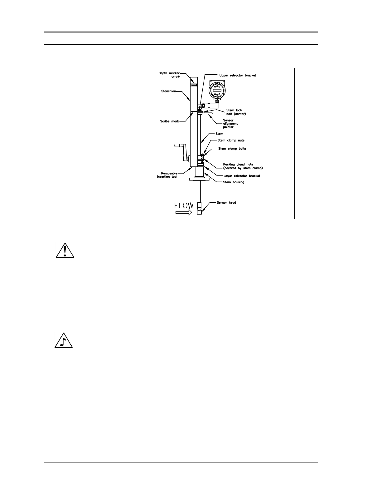
Figure 2-9. Flow Meter with Permanent Insertion Tool
1. Calculate the required sensor probe insertion length (see previous
page). Measure from the depth marker arrow down the stanchion and
scribe a mark at the calculated insertion depth.
2. Fully retract the flow meter until the sensor head is touching the bot-
tom of the stem housing. Attach the meter assembly to the two inch
full-port isolation valve, if used. Use Teflon tape or pipe sealant to
improve seal and prevent seizing on NPT style.
3. Loosen the two packing gland nuts on the stem housing of the meter.
Loosen the stem lock bolt adjacent to the sensor alignment pointer.
Align the sensor head using the sensor alignment pointer. Adjust the
alignment pointer parallel to the pipe and pointing downstream. Tighten
the stem lock bolt to secure the sensor position.
4. Slowly open the isolation valve to the full open position. If necessary,
slightly tighten the two packing gland nuts to reduce the leakage
around the stem.
5. Turn the insertion tool handle clockwise to insert the sensor head into
the pipe. Continue until the top of the upper retractor bracket aligns
with the insertion length position scribed on the stanchion. Do not
force the stem into the pipe.
6. Tighten the packing gland nuts to stop leakage around the stem. Do
not torque over 20 ft-lb.
Caution!
The sensor alignment
pointer must point
downstream, in the
direction of flow.
Note
If line pressure is above
500 psig, it could require
up to 25 ft lb of torque to
insert the flow meter.
Do not confuse this with
possible interference
in the pipe.
Page 36
Chapter 2 Installation Series M22/M23/M24 Instruction Manual
2-16 M-000-00010
Insertion Procedure for Flow Meters with Removable Insertion Tool
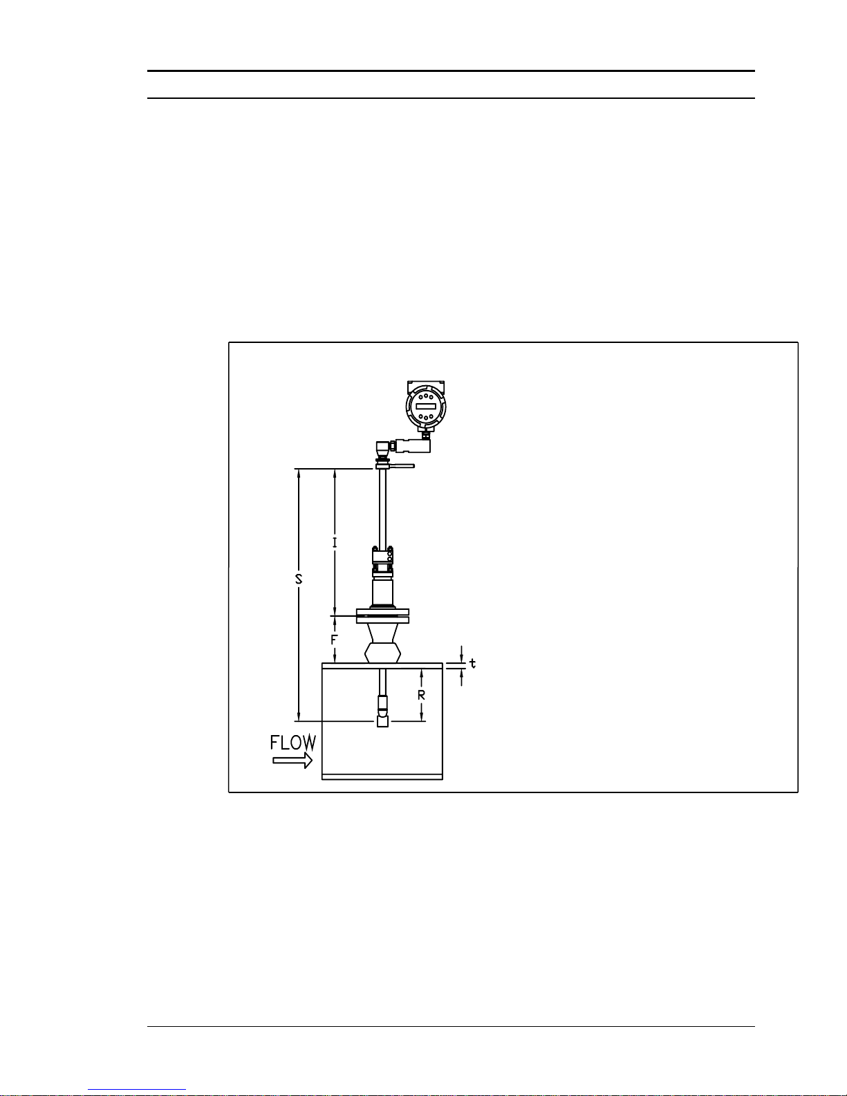
Figure 2-10. Flow Meter with Removable Insertion Tool
1. Calculate the required sensor probe insertion length. Measure from
the depth marker arrow down the stanchion and scribe a mark at the
calculated insertion depth.
2. Fully retract the flow meter until the sensor head is touching the bot-
tom of the stem housing. Attach the meter assembly to the two inch
full-port isolation valve, if used. Use Teflon tape or pipe sealant to
improve seal and prevent seizing on NPT style.
3. Remove the two top stem clamp nuts and loosen two stem clamp
bolts. Slide the stem clamp away to expose the packing gland nuts.
4. Loosen the two packing gland nuts. Loosen the stem lock bolt adja-
cent to the sensor alignment pointer. Align the sensor head using the
sensor alignment pointer. Adjust the alignment pointer parallel to the
pipe and pointing downstream. Tighten the stem lock bolt to secure
the sensor position.
5. Slowly open the isolation valve to the full open position. If necessary,
slightly tighten the two packing gland nuts to reduce the leakage
around the stem.
6. Turn the insertion tool handle clockwise to insert the stem into the
pipe. Continue until the top of the upper retractor bracket lines up
with the insertion length mark scribed on the stanchion. Do not force
the stem into the pipe.
Caution!
The sensor alignment
pointer must point
downstream, in the
direction of flow.
Note
If line pressure is above
500 psig, it could require
up to 25 ft lb of torque to
insert the flow meter.
Do not confuse this with
possible interference
in the pipe.
Page 37
Series M22/M23/M24 Instruction Manual Chapter 2 Installation
M-000-00010 2-17
7. Tighten the packing gland nuts to stop leakage around the stem. Do not
torque over 20 ft-lbs.
8. Slide the stem clamp back into position. Torque stem clamp bolts to 15
ft-lbs. Replace the stem clamp nuts and torque to 10-15 ft-lbs.
9. To separate the insertion tool from the flow meter, remove four socket
head cap bolts securing the upper and lower retractor brackets. Remove
the insertion tool.
Installation of Meters with Packing Gland Connection (No Insertion Tool)*
Use the following formula to determine insertion depth for meters with a
packing gland connection (NPT and flanged) without an insertion tool.
Insertion Length Formula
I = S – F – R – t
Where:
I = Insertion length.
S = Stem length – the distance from the
center of the sensor head to the base of the
enclosure adapter (S = 29.47 inches for
standard probes; S = 41.47 inches for 12 inch
extended probes).
F = Distance from the raised face of the
flange or top of NPT stem housing to the
outside of the pipe wall.
R = Pipe inside diameter 2 for pipes ten
inches & smaller.
R = Five inches for pipe diameters larger than ten
inches.
t = Thickness of the pipe wall. (Measure the disk
cut-out from the tapping procedure or check a piping
handbook for thickness.)
Figure 2-11. Insertion Calculation (Meters without Insertion Tool)
Example:
To install a Series M23 Flow Meter with a standard probe (S = 29.47) into
a 14 inch schedule 40 pipe, the following measurements are taken:
F = 3 inches
R = 5 inches
t = 0.438 inches
The example insertion length is 21.03 inches.
*All dimensions are in inches.
Page 38
Chapter 2 Installation Series M22/M23/M24 Instruction Manual
2-18 M-000-00010
Insertion Procedure for Flow Meters with No Insertion Tool
(Packing Gland Connection)
1. Calculate the required sensor probe insertion length.
2. Fully retract the stem until the sensor head is touching the bottom of the
stem housing. Remove the two top stem clamp nuts and loosen two
stem clamp bolts. Slide the stem clamp away to expose the packing
gland nuts. Loosen the two packing gland nuts.
3. Align the sensor head using the sensor alignment pointer. Adjust the
alignment pointer parallel to the pipe and pointing downstream.
4. Insert the sensor head into the pipe until insertion length, I, is
achieved. Do not force the stem into the pipe.
5. Tighten the packing gland nuts to stop leakage around the stem. Do
not torque over 20 ft-lbs.
6. Slide the stem clamp back into position. Torque stem clamp bolts to
15 ft-lbs. Replace the stem clamp nuts and torque to 10-15 ft-lbs.
Warning!
The line pressure
must be less than
50 psig for installation.
Caution!
The sensor alignment
pointer must point
downstream, in the
direction of flow.
Page 39
Series M22/M23/M24 Instruction Manual Chapter 2 Installation
M-000-00010 2-19
Adjusting Meter Orientation
Depending on installation requirements, you may need to adjust the meter
orientation. There are two adjustments available. The first rotates the position of the LCD display/keypad and is available on both in-line and insertion meters. The second is to rotate the enclosure position. This adjustment is only allowed on Series M22/M24 In-Line meters.
Display/Keypad Adjustment (All Meters)
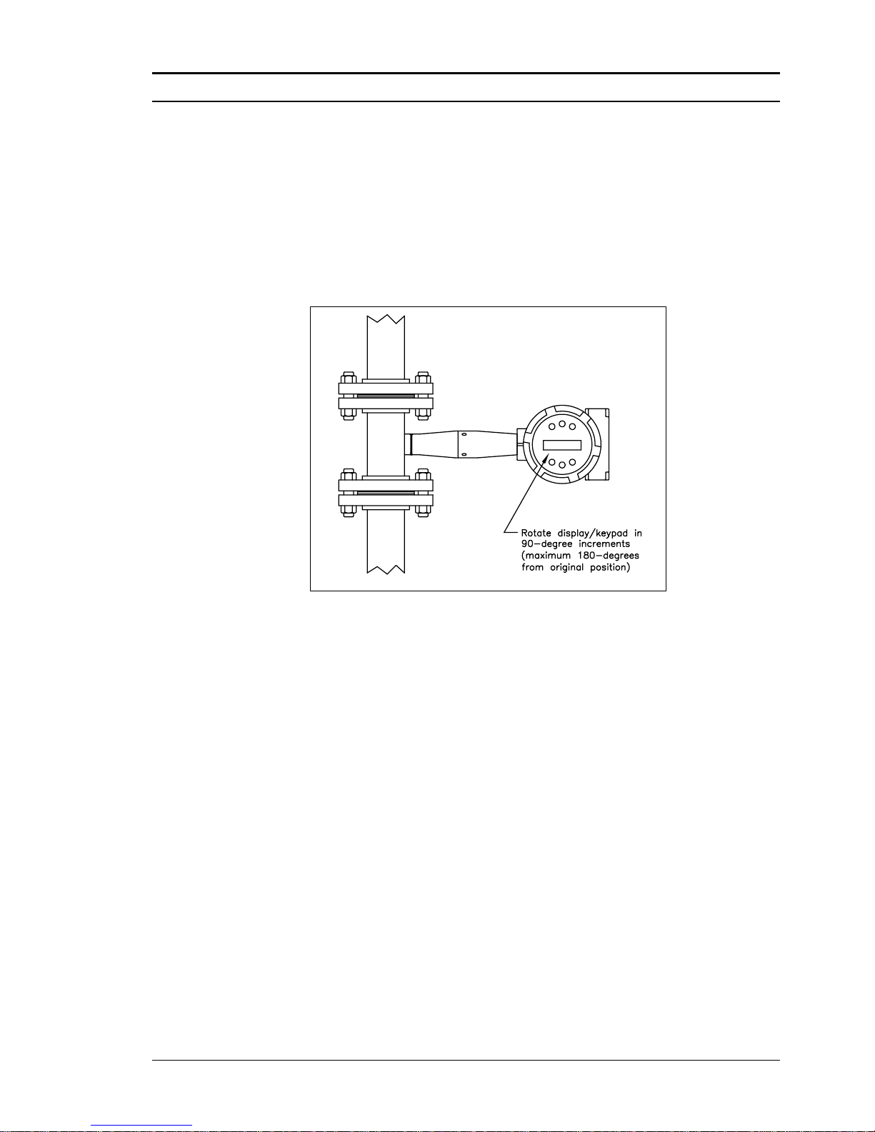
Figure 2-12. Display/Keypad Viewing Adjustment
The electronics boards are electrostatically sensitive. Wear a grounding
wrist strap and make sure to observe proper handling precautions required
for static-sensitive components. To adjust the display:
1. Disconnect power to the flow meter.
2. Loosen the small set screw which secures the electronics enclosure
cover. Unscrew and remove the cover.
3. Loosen the 4 captive screws.
4. Carefully pull the display/microprocessor board away from the meter
standoffs. Make sure not to damage the connected ribbon cable.
5. Rotate the display/microprocessor board to the desired position. Max-
imum turn, two positions left or two positions right (180-degrees).
6. Align the board with the captive screws. Check that the ribbon cable
is folded neatly behind the board with no twists or crimps.
7. Tighten the screws. Replace the cover and set screw. Restore power to
the meter.
Page 40
Chapter 2 Installation Series M22/M23/M24 Instruction Manual
2-20 M-000-00010
Enclosure Adjustment (Series M22/M24 Only)
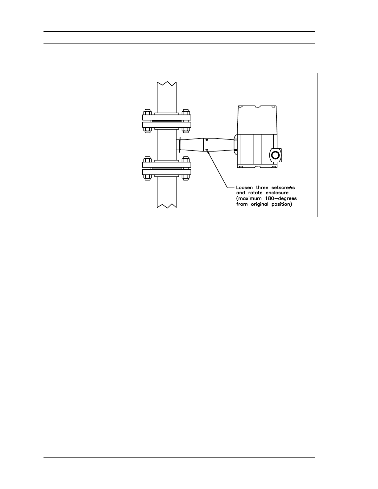
Figure 2-13. Enclosure Viewing Adjustment
To avoid damage to the sensor wires, do not rotate the enclosure beyond
180-degrees from the original position. To adjust the enclosure:
1. Remove power to the flow meter.
2. Loosen the three set screws shown above. Rotate the display to the
desired position (maximum 180-degrees).
3. Tighten the three set screws. Restore power to the meter.
Page 41
Series M22/M23/M24 Instruction Manual Chapter 2 Installation
M-000-00010 2-21
Loop Power Flow Meter Wiring Connections
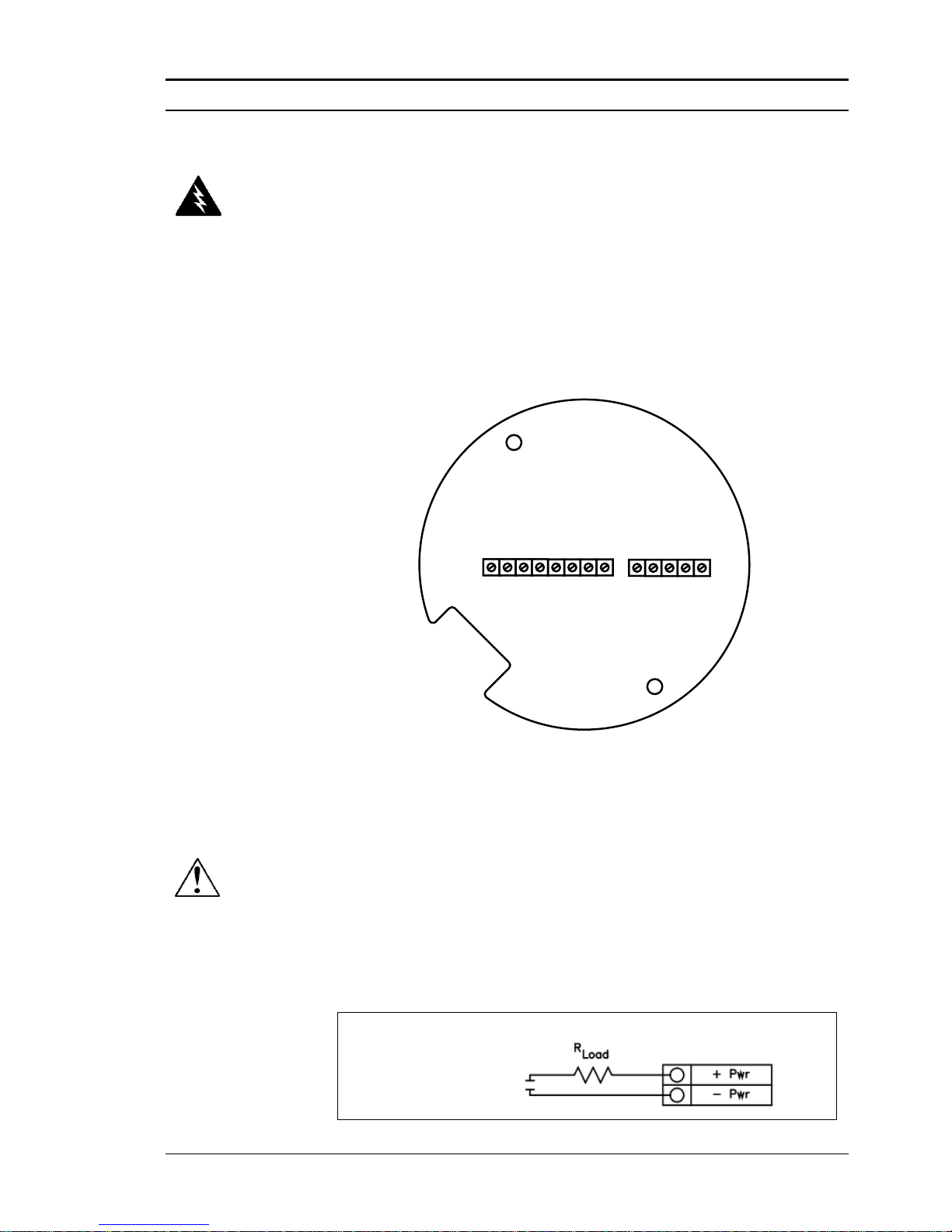
The NEMA 4X enclosure contains an integral wiring compartment with
one dual strip terminal block (located in the smaller end of the enclosure).
Two 3/4-inch female NPT conduit entries are available for separate power
and signal wiring. For all hazardous area installations, only suitable certified cable glands, blanking plugs or thread adapters may be used. The cable entry device shall be of a certified flameproof type, suitable for the
conditions of use and correctly installed. The degree of protection of at
least IP66 to EN 60529 is only achieved if certified cable entries are used
that are suitable for the application and correctly installed. Unused apertures shall be closed with suitable blanking elements. If conduit seals are
used, they must be installed within 18 inches (457 mm) of the enclosure.
LOOP
POWER
+ -
FREQ
OUT
PULSE
OUT
-- + +
OPTIONAL
BACKLIGHT
POWER
+ -
31 2 4 5
OPTION 2
Figure 2-14. Loop Power Wiring Terminals
Input Power Connections
To access the wiring terminal blocks, locate and loosen the small set
screw which locks the small enclosure cover in place. Unscrew the cover
to expose the terminal block.
DC Power Wiring
Connect 4-20 mA loop power (12 to 36 VDC at 25 mA, 1W max.) to the
+Loop Power and –Loop Power terminals on the terminal block. Torque
all connections to 4.43 to 5.31 in-lbs (0.5 to 0.6 Nm). The DC power wire
size must be 20 to 12 AWG with the wire stripped 1/4 inch (7 mm).
12 to 36 VDC
25 mA max.
Figure 2-15. DC Power Connections
Warning!
To avoid potential electric
shock, follow National Electric
Code safety practices or your
local code when wiring this
unit to a power source and to
peripheral devices. Failure to
do so could result in injury or
death. All wiring procedures
must be performed with the
power off.
Use a Class I or Class II
power supply.
A power switch is not provid-
ed with this meter, an ap-
proved switch meeting the
power requirements listed in
Appendix A must be provided
by the user. It must be easily
accessible and marked as the
disconnect for the flow meter.
Only the connectors supplied
with the meter are to be used
for connecting wiring.
If the equipment is used in a
manner not specified the pro-
tection provided by the
equipment may be impaired.
Caution!
The DC wire insulation temperature rating must meet or
exceed 85°C (185°F), maxi-
mum operating voltage 300
VRMS.
Page 42
Chapter 2 Installation Series M22/M23/M24 Instruction Manual
2-22 M-000-00010
4-20 mA Output Connections
The Pro-V meter has a single 4-20 mA loop. The 4-20 mA loop current is
controlled by the meter electronics. The electronics must be wired in series with the sense resistor or current meter. The current control electronics require 12 volts at the input terminals to operate correctly.
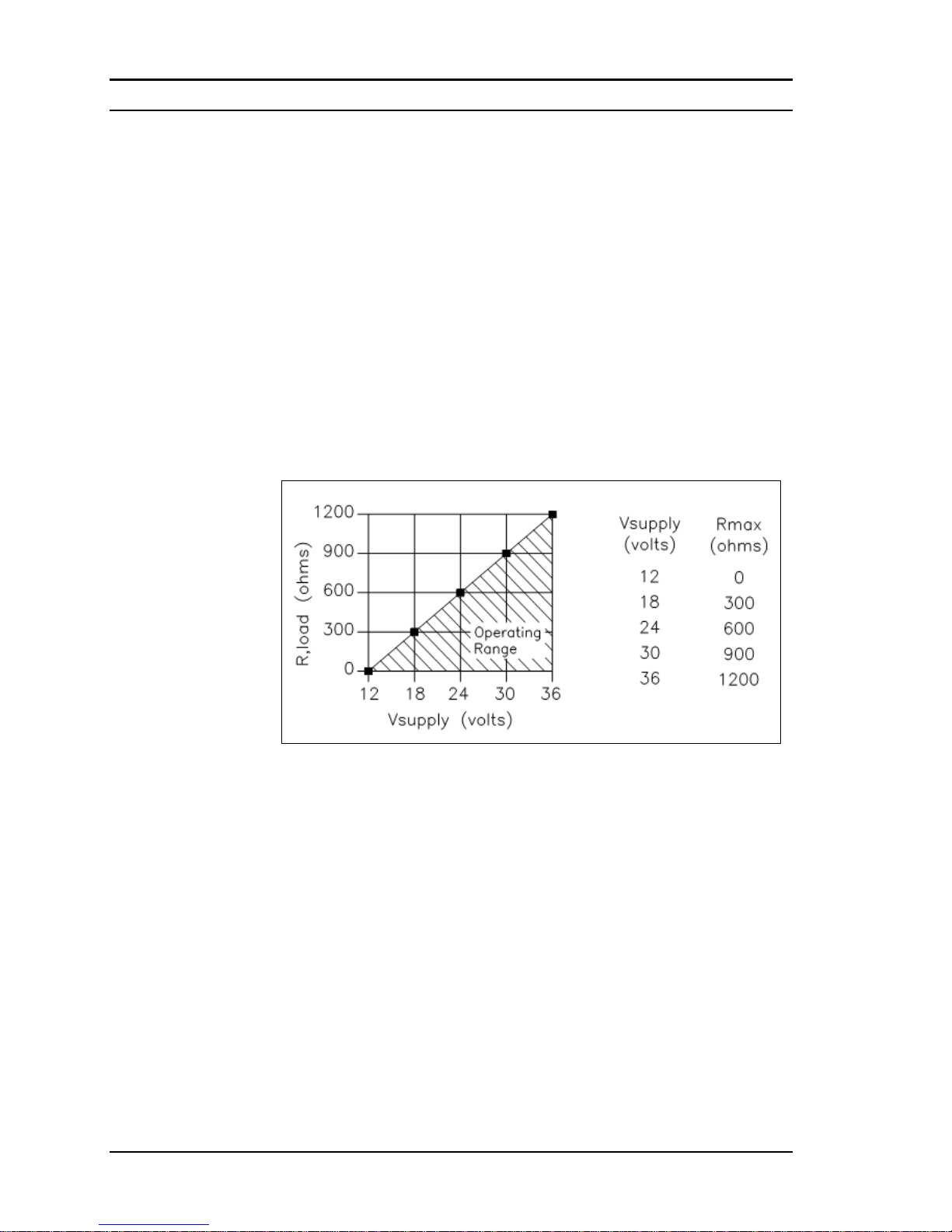
The maximum loop resistance (load) for the current loop output is dependent upon the supply voltage and is given in Figure 2-16. The 4-20
mA loop is optically isolated from the flow meter electronics.
R
load
is the total resistance in the loop, including the wiring resistance
(R
load
= R
wire
+ R
sense
). To calculate R
max
, the maximum R
load
for the loop,
subtract the minimum terminal voltage from the supply voltage and divide
by the maximum loop current, 20 mA. Thus:
The maximum resistance R
load
= R
max
= (V
supply
– 12V) / 0.020 A
Figure 2-16. Load Resistance Versus Input Voltage
The current loop range is 3.8 to 20.5 mA.
Page 43
Series M22/M23/M24 Instruction Manual Chapter 2 Installation
M-000-00010 2-23
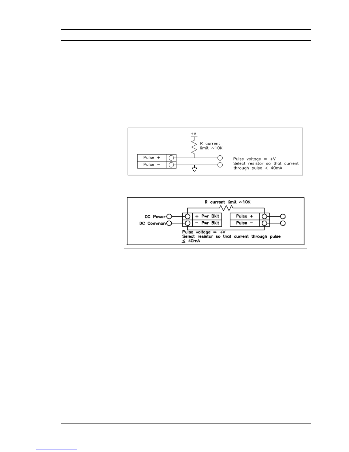
Pulse Output Connections
The pulse output is used for a remote counter. When the preset volume or
mass (defined in the totalizer settings, see page 3-10) has passed the meter, the output provides a 50 millisecond square pulse.
The pulse output requires a separate 5 to 36 VDC power supply. The
pulse output optical relay is a normally-open single-pole relay. The relay
can conduct a current up to 40 mA. It is isolated from the meter electronics and power supply.
Figure 2-17. Isolated Pulse Output Using External Power Supply
Figure 2-18. Non-Isolated Pulse Output Using External Power Supply
Page 44
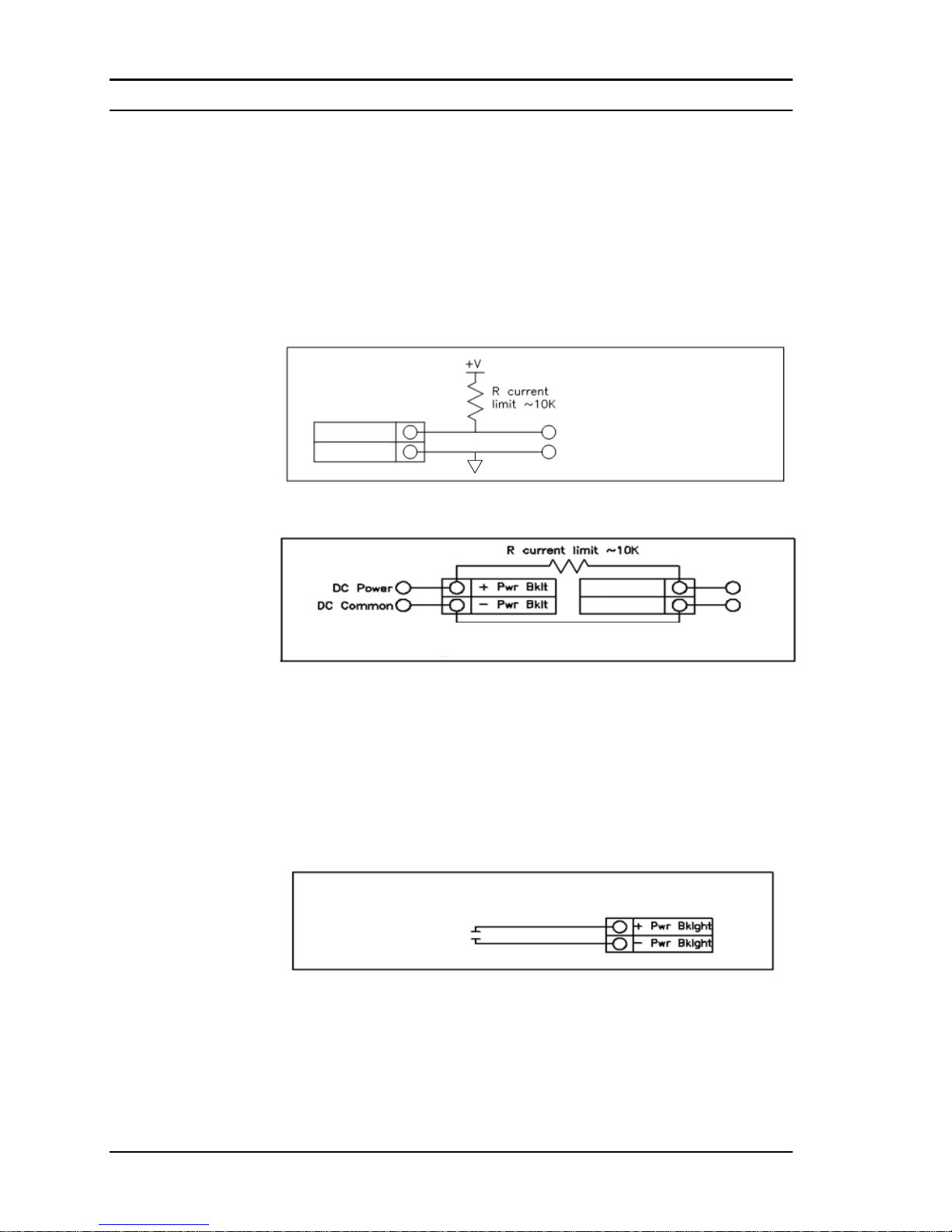
Chapter 2 Installation Series M22/M23/M24 Instruction Manual
2-24 M-000-00010
Frequency Output Connections
The frequency output is used for a remote counter. It can be scaled to output a 1 to 10 kHz signal proportional to mass or volume flow, temperature, pressure or density.
The frequency output requires a separate 5 to 36 VDC power supply. The
frequency output optical relay is a normally-open single-pole relay. The
output can conduct a current up to 40 mA. It is isolated from the meter
electronics and power supply.
Freq. Out -
Freq. Out +
Freq. Out voltage = +V
Select resistor so that current
through Freq. Out <= 40 mA
Figure 2-19. Isolated Frequency Output Using External Power Supply
Freq. Out voltage = +V
Select resistor so that current through Freq. Out <= 40 mA
Freq. Out +
Freq. Out -
Figure 2-20. Non-Isolated Frequency Output Using External Power Supply
Optional Backlight Connection
The loop power meter has an optional backlight connection provided. It is
intended to be powered by a separate 12 to 36 VDC at 35 mA max. power
supply or by the pulse power input. Both options are shown below.
12 to 36 VDC
35 mA max.
Figure 2-21.Backlight Using External Power Supply
Page 45
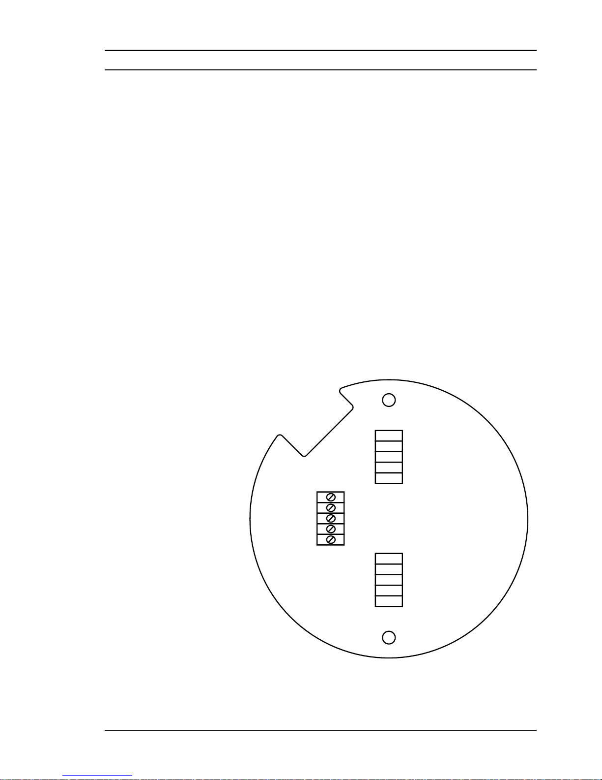
Series M22/M23/M24 Instruction Manual Chapter 2 Installation
M-000-00010 2-25
Remote Electronics Wiring
The remote electronics enclosure should be mounted in a convenient, easy
to reach location. For hazardous location installations, make sure to observe agency requirements for installation. Allow some slack in the interface cable between the junction box and the remote electronics enclosure.
To prevent damage to the wiring connections, do not put stress on the
terminations at any time.
The meter is shipped with temporary strain relief glands at each end of the
cable. Disconnect the cable from the meter’s terminal block inside the
junction box–not at the remote electronics enclosure. Remove both glands
and install appropriate conduit entry glands and conduit. The cable entry
device shall be of a certified flameproof type, suitable for the conditions
of use and correctly installed. The degree of protection of at least IP66 to
EN 60529 is only achieved if certified cable entries are used that are suitable for the application and correctly installed. Unused apertures shall be
closed with suitable blanking elements. When installation is complete, reconnect each labeled wire to the corresponding terminal position on the
junction box terminal block. Make sure to connect each wire pair’s shield.
Note: incorrect connection will cause the meter to malfunction.
Note: Numeric code on junction box label matches wire labels.
NOT USED
RED 2
SHLD 1&2
BLK 2
SENSOR V2
SHIELD
SENSOR V1
FLOW
BLK 1
PWR
GND
RED 1
NOT USED
Figure 2-22. Loop Power Volumetric Flowmeter Junction Box Sensor Connections
(Wires enter the flow connector from the left side of the connector shown
above.)
Page 46
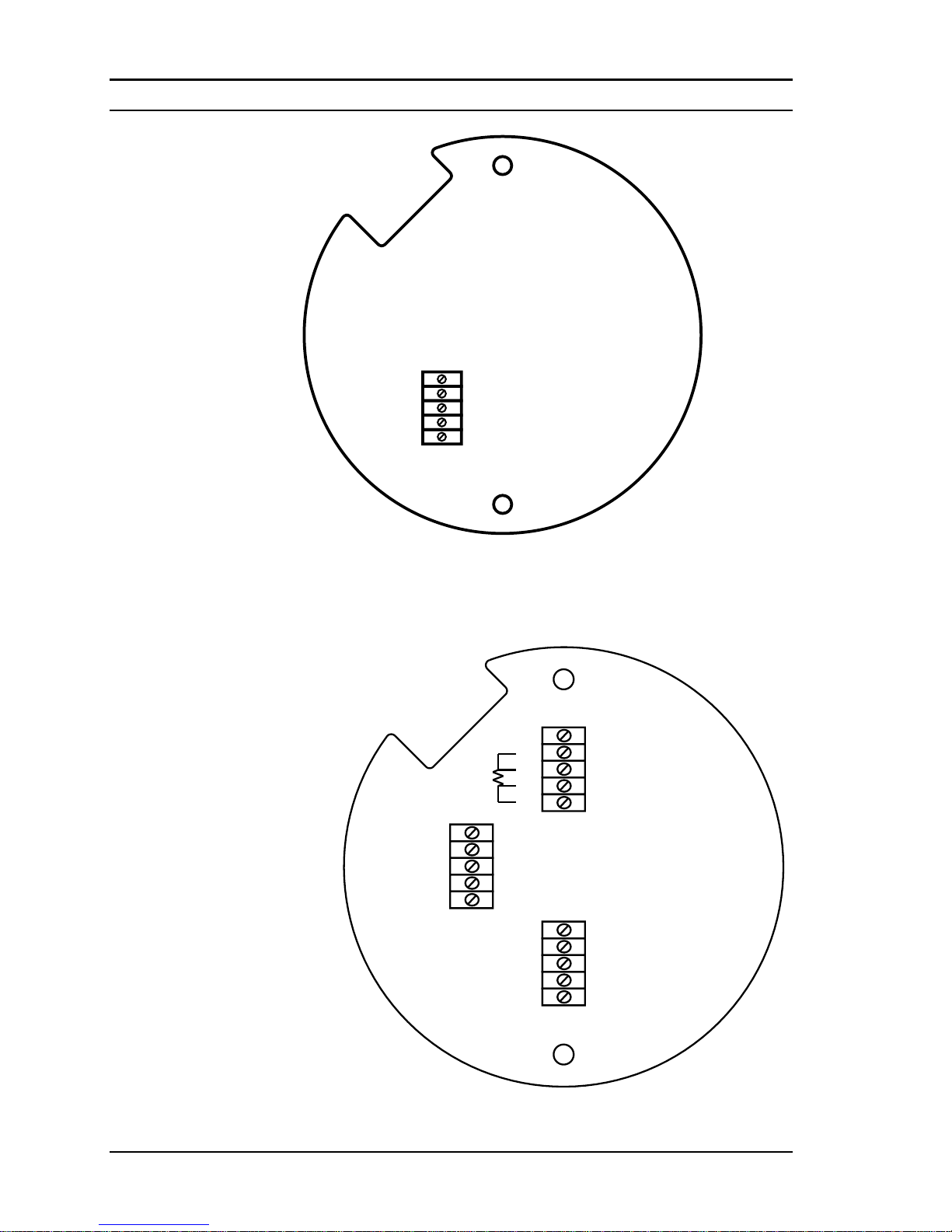
Chapter 2 Installation Series M22/M23/M24 Instruction Manual
2-26 M-000-00010
RED 1
BLK 1
BLK 2
RED 2
SHLD 1&2
SENSOR V1
VORTEX
GND
PWR
SENSOR V2
SHIELD
Figure 2-23. Loop Power Volumetric Flowmeter Junction Box Sensor Connections Supplied Prior to Jan. 1, 2014 (Wires enter the flow connector
from the right side of the connector shown above.)
PRESSURE
TEMPERATURE
RED 2
SHLD 1&2
BLK 2
SHIELD
SHIELD
SENSOR V2
SHIELD
SENSOR V1
VORTEX
BLK 1
PWR
S1
E1
S2
T2
T1
T3
E2 T4
GND
RED 1
P3
P1
P2
P4
SHLD 3&4
SHLD 5&6
RED 6
BLK 6
BLK 5
RED 5
BLK 3
BLK 4
RED 4
RED 3
Figure 2-24. Loop Power Mass Flowmeter Junction Box Sensor Connections
Page 47
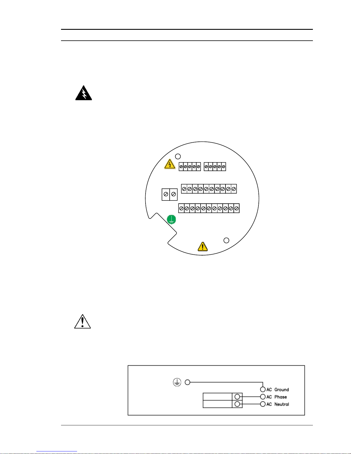
Series M22/M23/M24 Instruction Manual Chapter 2 Installation
M-000-00010 2-27
High Power Meter Wiring Connections
The NEMA 4X enclosure contains an integral wiring compartment with
one dual strip terminal block (located in the smaller end of the enclosure).
Two 3/4-inch female NPT conduit entries are available for separate power
and signal wiring. For all hazardous area installations, only suitable certified cable glands, blanking plugs or thread adapters may be used. The cable entry device shall be of a certified flameproof type, suitable for the
conditions of use and correctly installed. The degree of protection of at
least IP66 to EN 60529 is only achieved if certified cable entries are used
that are suitable for the application and correctly installed. Unused apertures shall be closed with suitable blanking elements. If conduit seals are
used, they must be installed within 18 inches (457 mm) of the enclosure.
4-20
mA 3
AC
PWR
IN
4-20
mA 1
24
VDC
OUT
+ - +
4-20
mA 2
- + - +
RS485
RS485
RS485 GND
-
OPTION 2
+
ALARM
2
HOT / L1
PULSE
OUT
NEUT / L2
FREQ
OUT
+ - +
ALARM
1
-+ -
4
OPTION 1
1 2 3 15 2 3
ALARM
3
- + -
4 5
+
-
Figure 2-25. AC Wiring Terminals
Input Power Connections
To access the wiring terminal blocks, locate and loosen the small set
screw which locks the small enclosure cover in place. Unscrew the cover
to expose the terminal block.
AC Power Wiring
The AC power wire size must be 20 to 10 AWG with the wire stripped
1/4 inch (7 mm). The wire insulation temperature must meet or exceed
90°C (194°F). Connect 100 to 240 VAC (5 W maximum) to the Hot and
Neutral terminals on the terminal block. Connect the ground wire to the
safety ground lug. Torque all connections to 4.43 to 5.31 in-lbs (0.5 to 0.6
Nm). Use a separate conduit entry for signal lines to reduce the possibility
of AC noise interference.
100 to 240 VAC, 50/60 Hz, 5 Watts Max.
Chassis screw safety
ground must be used
for proper operation.
Hot / L1
Neutral / L2
Figure 2-26. AC Power Connections
Warning!
To avoid potential electric shock, follow
National Electric Code safety practices or
your local code when wiring this unit to a
power source and to peripheral devices.
Failure to do so could result in injury or
death. All AC power connections must be
in accordance with published CE direc-
tives. All wiring procedures must be per-
formed with the power off.
A power switch is not provided with this
meter, an approved switch meeting the
power requirements listed in Appendix A
must be provided by the user. It must be
easily accessible and marked as the dis-
connect for the flow meter.
Only the connectors supplied with the me-
ter are to be used for connecting wiring.
If the equipment is used in a manner not
specified the protection provided by the
equipment may be impaired.
Caution!
The AC wire insulation temperature rating
must meet or exceed 90°C (194°F), max-
imum operating voltage 600 VRMS.
Page 48
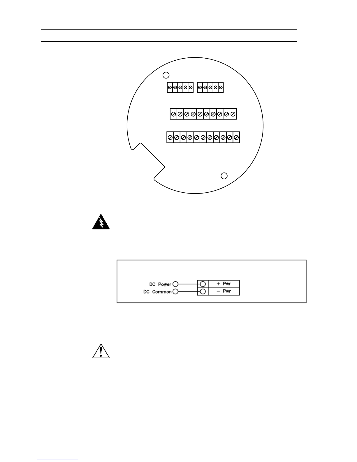
Chapter 2 Installation Series M22/M23/M24 Instruction Manual
2-28 M-000-00010
4-20
mA 3
4-20
mA 1
DC
PWR
+ - +
4-20
mA 2
- + - +
RS485
RS485
RS485 GND
-
OPTION 2
+
ALARM
2
PULSE
OUT
FREQ
OUT
+ - +
ALARM
1
-+ -
4
OPTION 1
1 2 3 15 2 3
ALARM
3
- + -
4 5
+
-
Figure 2-27. DC Wiring Terminals
DC Power Wiring
The DC power wire size must be 20 to 12 AWG with the wire
stripped 1/4 inch (7 mm). Connect 18 to 36 VDC (300 mA, 9 W maximum) to the +DC Pwr and –DC Pwr terminals on the terminal block.
Torque all connections to 4.43 to 5.31 in-lbs (0.5 to 0.6 Nm).
18 to 36 VDC @ 300 mA Max.
Figure 2-28. DC Power Connections
Warning!
Use a Class I or Class II power supply.
A power switch is not provided with this me-
ter, an approved switch meeting the power
requirements listed in Appendix A must be
provided by the user. It must be easily ac-
cessible and marked as the disconnect for
the flow meter.
Only the connectors supplied with the meter
are to be used for connecting wiring.
If the equipment is used in a manner not
specified the protection provided by the
equipment may be impaired
Caution!
The DC wire insulation temperature rating
must meet or exceed 85°C (185°F), maxi-
mum operating voltage 300 VRMS.
Page 49
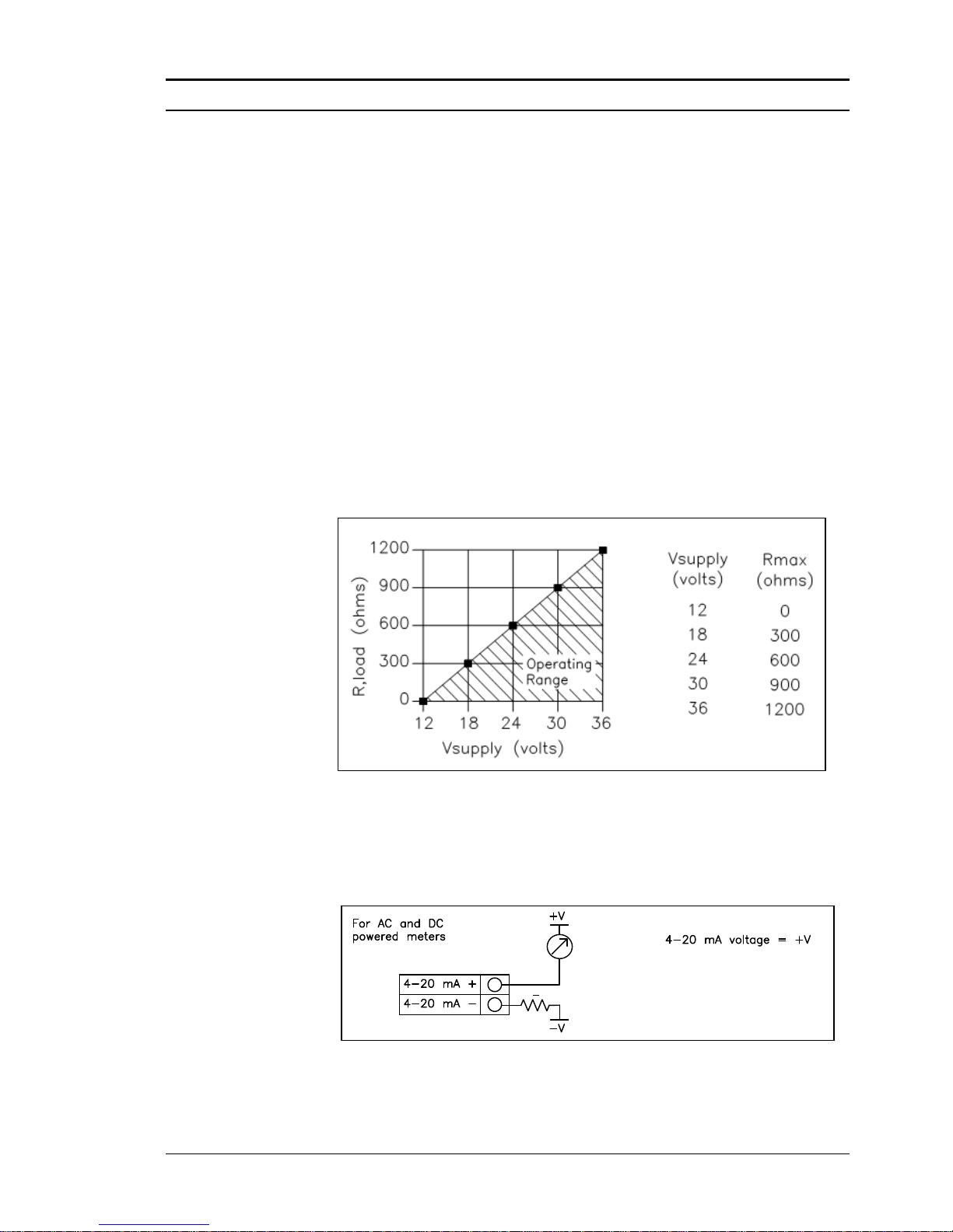
Series M22/M23/M24 Instruction Manual Chapter 2 Installation
M-000-00010 2-29
4-20 mA Output Connections
The standard Pro-V Flow Meter has a single 4-20 mA loop. Two additional loops are available on the optional communication board. The 4-20
mA loop current is controlled by the meter electronics. The electronics
must be wired in series with the sense resistor or current meter. The current control electronics require 12 volts at the input terminals to operate
correctly.
The maximum loop resistance (load) for the current loop output is dependent upon the supply voltage and is given in Figure 2-29. The 4-20 mA loop
is optically isolated from the flow meter electronics.
R
load
is the total resistance in the loop, including the wiring resistance
(R
load
= R
wire
+ R
sense
). To calculate R
max
, the maximum R
load
for the loop,
subtract the minimum terminal voltage from the supply voltage and divide
by the maximum loop current, 20 mA. Thus:
The maximum resistance R
load
= R
max
= (V
supply
– 12V) / 0.020 A
Figure 2-29. Load Resistance Versus Input Voltage
The current loop range is 3.8 to 20.5 mA.
For Hart Communications
signal loop must have a
minimum of 250 ohms load
resistance R
L
RL> 250
mA
Meter
Figure 2-30. Isolated 4–20 mA Output Using External Power Supply
Page 50
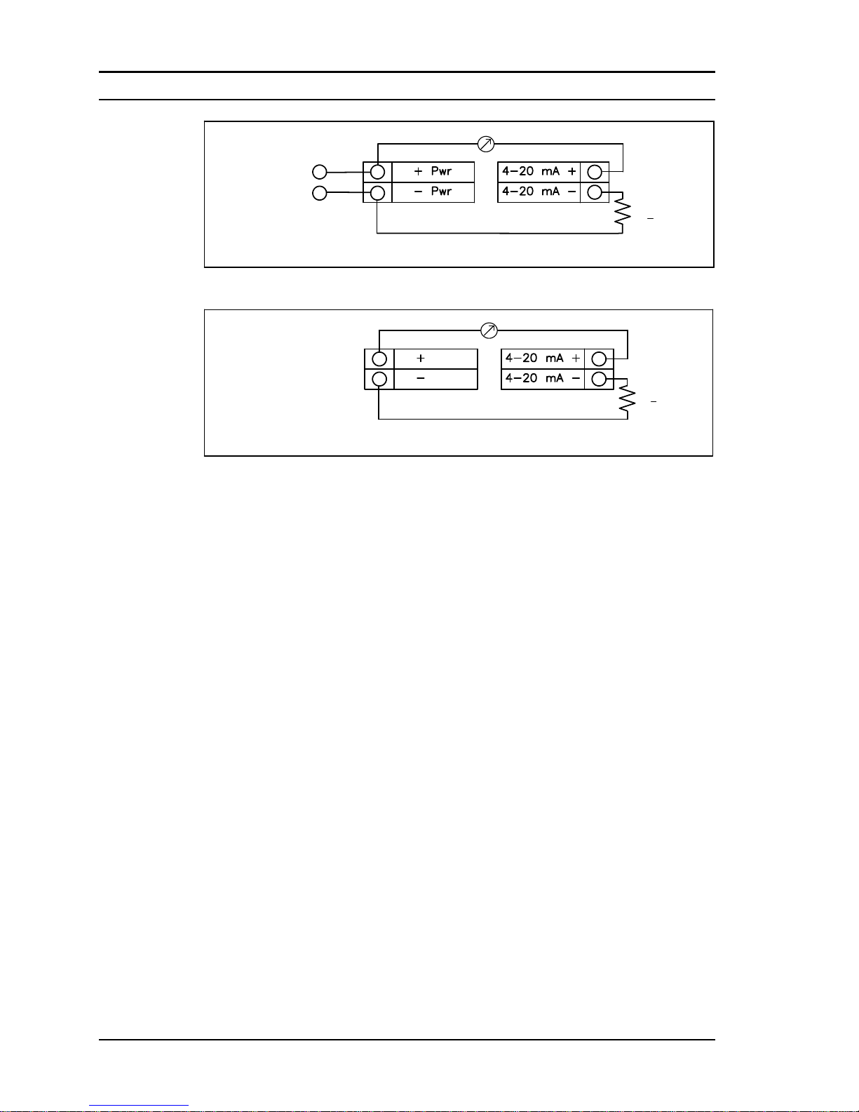
Chapter 2 Installation Series M22/M23/M24 Instruction Manual
2-30 M-000-00010
DC powered meters only
RL > 250 Ohm
DC Power
DC Common
mA Meter
For HART
communications
the signal loop
must have a
minimum of 250
ohms load
resistance.
Figure 2-31. Non-Isolated 4–20 mA Output Using Meter Input Power Supply
AC units only
Meter Provided DC
Power
RL> 250 Ohm
24 VDC
24 VDC
For HART
communications
the signal loop
must have a
minimum of 250
ohms load
resistance.
mA Meter
Figure 2-32. Isolated 4–20 mA Output Using Meter Provided Power Supply
Frequency Output Connections
The frequency output is used for a remote counter. It can be scaled to output a 1 to 10 kHz signal proportional to mass or volume flow, temperature, pressure or density.
The frequency output requires a separate 5 to 36 VDC power supply. The
frequency output optical relay is a normally-open single-pole relay. The
output can conduct a current up to 40 mA. It is isolated from the meter
electronics and power supply.
There are three connection options for the frequency output–the first with a
separate power supply (Figure 2-33), the second using the flow meter power
supply (Figure 2-34)(DC powered units only), and the third using the internal 24 VDC power supply (Figure 2-35)(AC powered units only). Use the
first option with a separate power supply (5 to 36 VDC) if a specific voltage
is needed for the frequency output. Use the second configuration if the voltage at the flow meter power supply is an acceptable driver voltage for the
load connected. (Take into account that the current used by the frequency
load comes from the meter’s power supply). Use the third configuration if
you have an AC powered unit only. In any case, the voltage of the frequency output is the same as the voltage supplied to the circuit.
Page 51
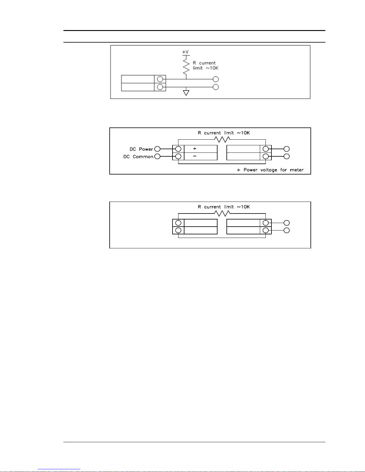
Series M22/M23/M24 Instruction Manual Chapter 2 Installation
M-000-00010 2-31
Freq. Out -
Freq. Out +
Freq. Out voltage = +V
Select resistor so that current
through Freq . Out <= 40 mA
Figure 2-33. Isolated Frequency Output Using External Power Supply
PWR
PWR
DC Powered meters only
Freq. Out voltage =
Freq. Out +
Freq. Out -
Figure 2-34. Non-Isolated Frequency Output Using Input Power Supply
+ 24 VDC Out
-24 VDC Out
AC units only
Meter provided DC Power
Freq. Out +
Freq. Out -
Freq. Out voltage = +24 VDC
Figure 2-35. Isolated Frequency Output Using Meter Provided Power Supply
Pulse Output Connections
The pulse output is used for a remote counter. When the preset volume or
mass (defined in the totalizer settings, see page 3-10) has passed the meter, the output provides a 50 millisecond square pulse.
The pulse output requires a separate 5 to 36 VDC power supply. The
pulse output optical relay is a normally-open single-pole relay. The relay
can conduct a current up to 40 mA. It is isolated from the meter electronics and power supply.
There are three connection options for the pulse output–the first with a separate power supply (Figure 2-36), the second using the flow meter power
supply (Figure 2-37)(DC powered units only), and the third using the internal 24 VDC power supply (Figure 2-38)(AC powered units only). Use the
first option with a separate power supply (5 to 36 VDC) if a specific voltage
is needed for the pulse output. Use the second configuration if the voltage at
the flow meter power supply is an acceptable driver voltage for the load
connected. (Take into account that the current used by the pulse load comes
from the meter’s power supply). Use the third configuration if you have an
Page 52
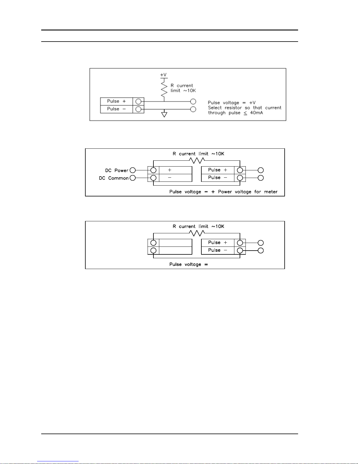
Chapter 2 Installation Series M22/M23/M24 Instruction Manual
2-32 M-000-00010
AC powered unit only. In any case, the voltage of the pulse output is the
same as the voltage supplied to the circuit.
Figure 2-36. Isolated Pulse Output Using External Power Supply
PWR
PWR
DC Powered meters only
Figure 2-37. Non-Isolated Pulse Output Using Input Power Supply
+ 24 VDC Out
- 24 VDC Out
AC units only
Meter provided DC Power
+24 VDC
Figure 2-38. Isolated Pulse Output Using Meter Provided Power Supply
Page 53
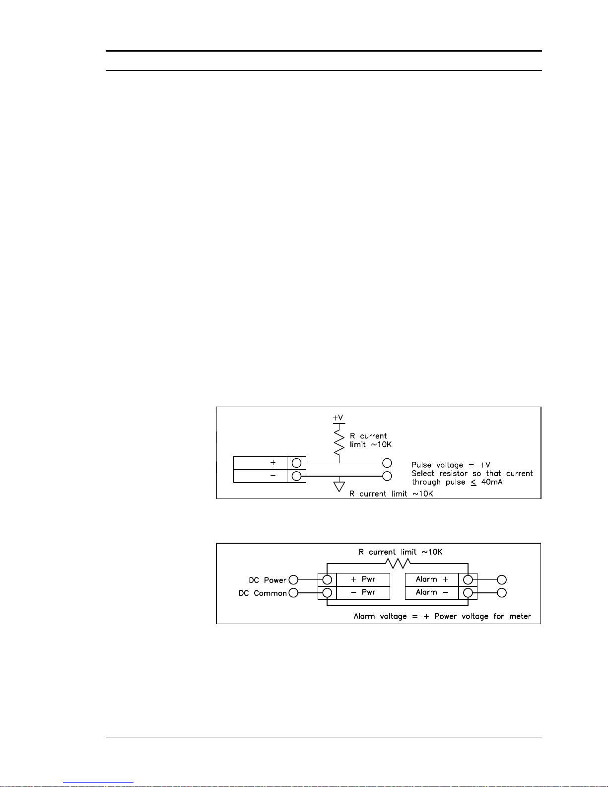
Series M22/M23/M24 Instruction Manual Chapter 2 Installation
M-000-00010 2-33
Alarm Output Connections
One alarm output (Alarm 1) is included on the standard Pro-V™ Flow
Meter. Two or more alarms (Alarm 2 and Alarm 3) are included on the
optional communication board. The alarm output requires a separate 5 to
36 VDC power supply. The alarm output optical relay is a normally-open
single-pole relay. The relay can conduct a current up to 40 mA. It is isolated from the meter electronics and power supply. When the alarm relay
is closed, the current draw will be constant. Make sure to size R
load
appro-
priately.
There are three connection options for the alarm output–the first with a separate power supply (Figure 2-39), the second using the flow meter power
supply (Figure 2-40)(DC powered units only) and the third with the meter
provided power supply (Figure 2-41)(AC powered units only). Use the first
option with a separate power supply (5 to 36 VDC) if a specific voltage is
needed for the alarm output. Use the second configuration if the voltage at
the flow meter power supply is an acceptable driver voltage for the load
connected. (Take into account that the current used by the alarm load comes
from the meter’s power supply). Use the third if you have an AC powered
unit only. In any case, the voltage of the alarm output is the same as the
voltage supplied to the circuit.
The alarm output is used for transmitting high or low process conditions
as defined in the alarm settings (see page 3-9).
AC or DC powered meters
ALARM
ALARM
Figure 2-39. Isolated Alarm Output Using External Power Supply
DC units only
Figure 2-40. Non-Isolated Alarm Output Using Internal Power Supply
Page 54
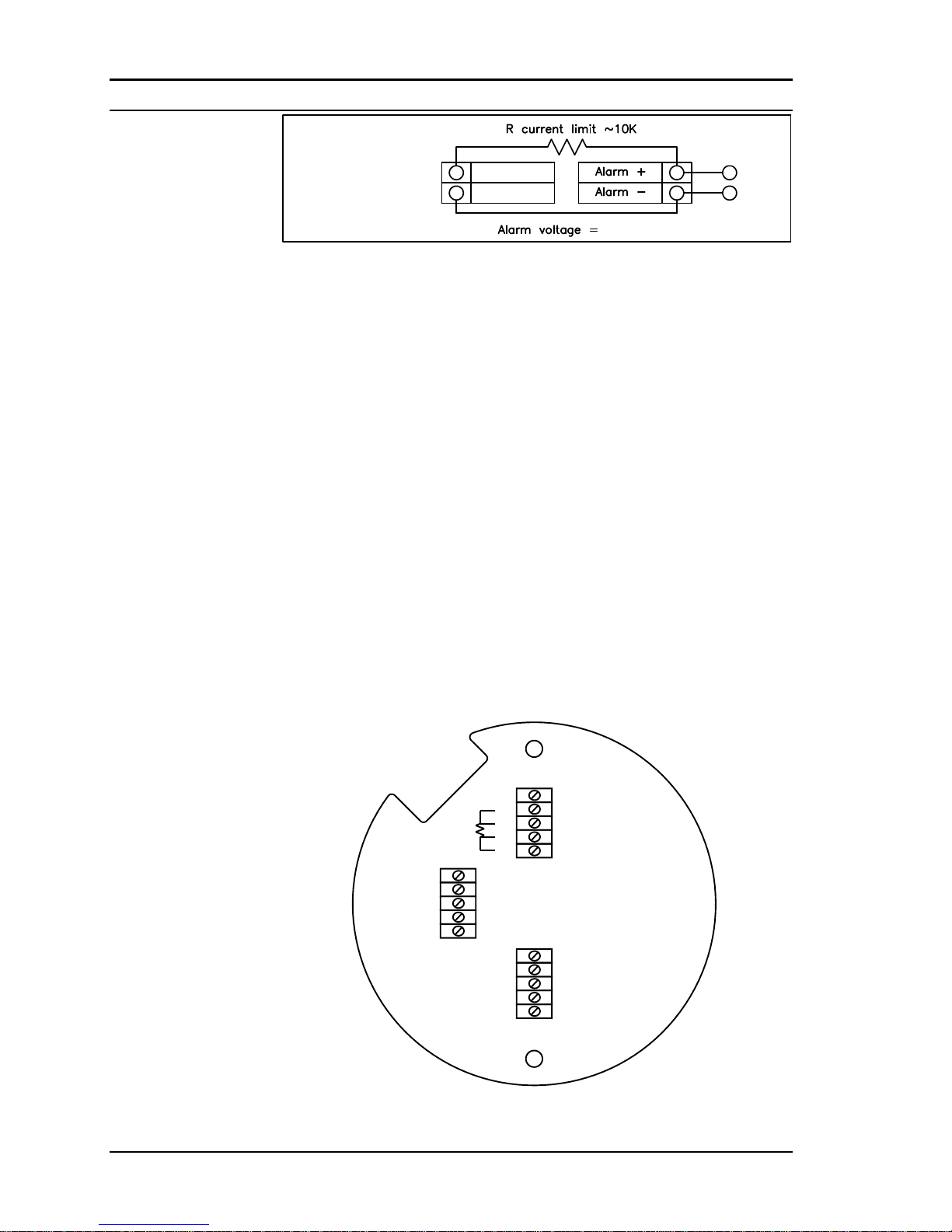
Chapter 2 Installation Series M22/M23/M24 Instruction Manual
2-34 M-000-00010
+ 24 VDC Out
- 24 VDC Out
AC units only
Meter provided
DC Power
+24 VDC
Figure 2-41. Isolated Alarm Output Using Meter Provided Power Supply
Remote Electronics Wiring
The remote electronics enclosure should be mounted in a convenient, easy
to reach location. For hazardous location installations, make sure to observe agency requirements for installation. Allow some slack in the interface cable between the junction box and the remote electronics enclosure.
To prevent damage to the wiring connections, do not put stress on the
terminations at any time.
The meter is shipped with temporary strain relief glands at each end of the
cable. Disconnect the cable from the meter’s terminal block inside the
junction box–not at the remote electronics enclosure. Remove both glands
and install appropriate conduit entry glands and conduit. The cable entry
device shall be of a certified flameproof type, suitable for the conditions
of use and correctly installed. The degree of protection of at least IP66 to
EN 60529 is only achieved if certified cable entries are used that are suitable for the application and correctly installed. Unused apertures shall be
closed with suitable blanking elements. When installation is complete, reconnect each labeled wire to the corresponding terminal position on the
junction box terminal block. Make sure to connect each wire pair’s shield.
Note: incorrect connection will cause the meter to malfunction.
PRESSURE
TEMPERATURE
RED 2
SHLD 1&2
BLK 2
SHIELD
SHIELD
SENSOR V2
SHIELD
SENSOR V1
VORTEX
BLK 1
PWR
S1
E1
S2
T2
T1
T3
E2 T4
GND
RED 1
P3
P1
P2
P4
SHLD 3&4
SHLD 5&6
RED 6
BLK 6
BLK 5
RED 5
BLK 3
BLK 4
RED 4
RED 3
Figure 2-42. High Power Flow Meter Junction Box Sensor Connections
Note: Numeric code on junction box label matches wire labels.
Page 55
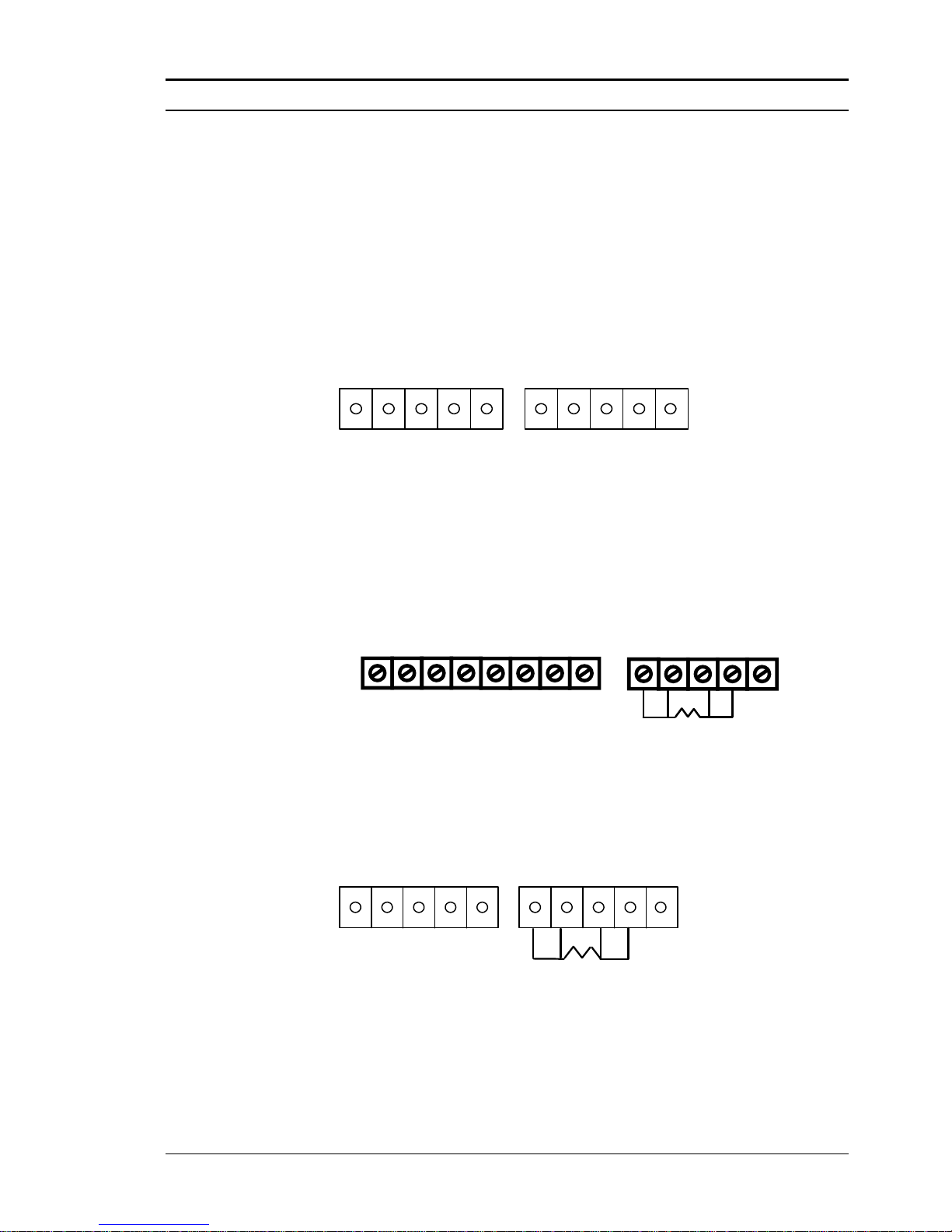
Series M22/M23/M24 Instruction Manual Chapter 2 Installation
M-000-00010 2-35
Optional Input Electronics Wiring
The meter has two optional input wiring terminals, maximum wire size is
16 AWG. These can be used to input a Remote or Second RTD input in
the case of an Energy Monitoring meter, for the input of a Remote Pressure Transducer, to pass a Contact Closure or for a Remote Density measurement to name a few. In any case, the wiring diagram will be included
with the meter if any of the options are specified. Otherwise, the optional
terminal blocks will be left blank and nonfunctional.
Option 2Option 1
1 2 3 4 5 1 2 3 4 5
Optional Energy EMS RTD Input Wiring
Loop Power
LOOP
POWER
+ -
FREQ
OUT
PULSE
OUT
-- + +
OPTIONAL
BACKLIGHT
POWER
+ -
31 2 4 5
OPTION 2
R = 1000 ohm
Red
Red
Black Black
* Other input options available.
High Power
Option 2Option 1
1 2 3 4 5 1 2 3 4 5
R = 1000 ohm
Red
Red
Black Black
Figure 2-43.Optional Energy EMS RTD Input Wiring
The recommended customer supplied second RTD is a Class A 1000 ohm
4-wire platinum RTD. If a second RTD is not being used, then the factory
supplied 1000 ohm resistor needs to be installed in its place.
Page 56
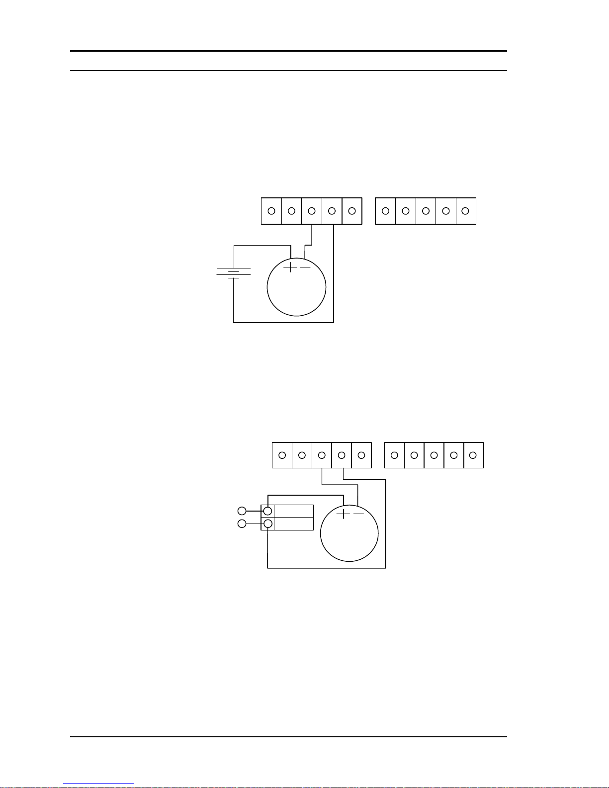
Chapter 2 Installation Series M22/M23/M24 Instruction Manual
2-36 M-000-00010
Optional External 4-20 mA Input Wiring
The meter is set to have Option 1 used for the external input. Programming menus that pertain to the optional 4-20 mA input are located in the
Hidden Diagnostics Menu in Chapter 5.
Option 2Option 1
1 2 3 4 5 1 2 3 4 5
Power
Ext. 4-20 mA
Input Device
External
+
-
Figure 2-44. External 4-20 mA Input Wiring - External Power Supply
Follow the above diagram to wire the external 4-20 mA input into the
flow meter using an external power supply.
Option 2Option 1
1 2 3 4 5 1 2 3 4 5
Ext. 4-20 mA
Input Device
+ DC PWR
- DC PWR
DC PWR
DC COMMON
DC powered meter only.
Figure 2-45. External 4-20 mA Input Wiring - DC Powered Meter
Follow the above diagram to wire the external 4-20 mA input into the
flow meter using power supplied to the input of a DC powered meter.
Page 57
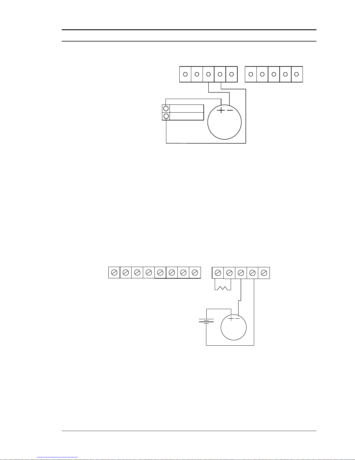
Series M22/M23/M24 Instruction Manual Chapter 2 Installation
M-000-00010 2-37
Option 2Option 1
1 2 3 4 5 1 2 3 4 5
Ext. 4-20 mA
Input Device
+ 24 VDC OUT
- 24 VDC OUT
AC units only. Meter
provided DC power.
Figure 2-46. External 4-20 mA Input Wiring - AC Powered Meter
Follow the above diagram to wire the external 4-20 mA input into the
flow meter using power from the 24 VDC output of an AC powered meter.
Optional External 4-20 mA Input and RTD Wiring
Loop Power
LOOP
POWER
+ -
FREQ
OUT
PULSE
OUT
-- + +
OPTIONAL
BACKLIGHT
POWER
+ -
31 2 4 5
OPTION 2
Power
External
+
-
Ext. 4-20 mA
Input Device
R = 1000 ohm
Red
Black
Figure 2-47. External 4-20 mA Input and RTD Wiring – Loop Power
Page 58
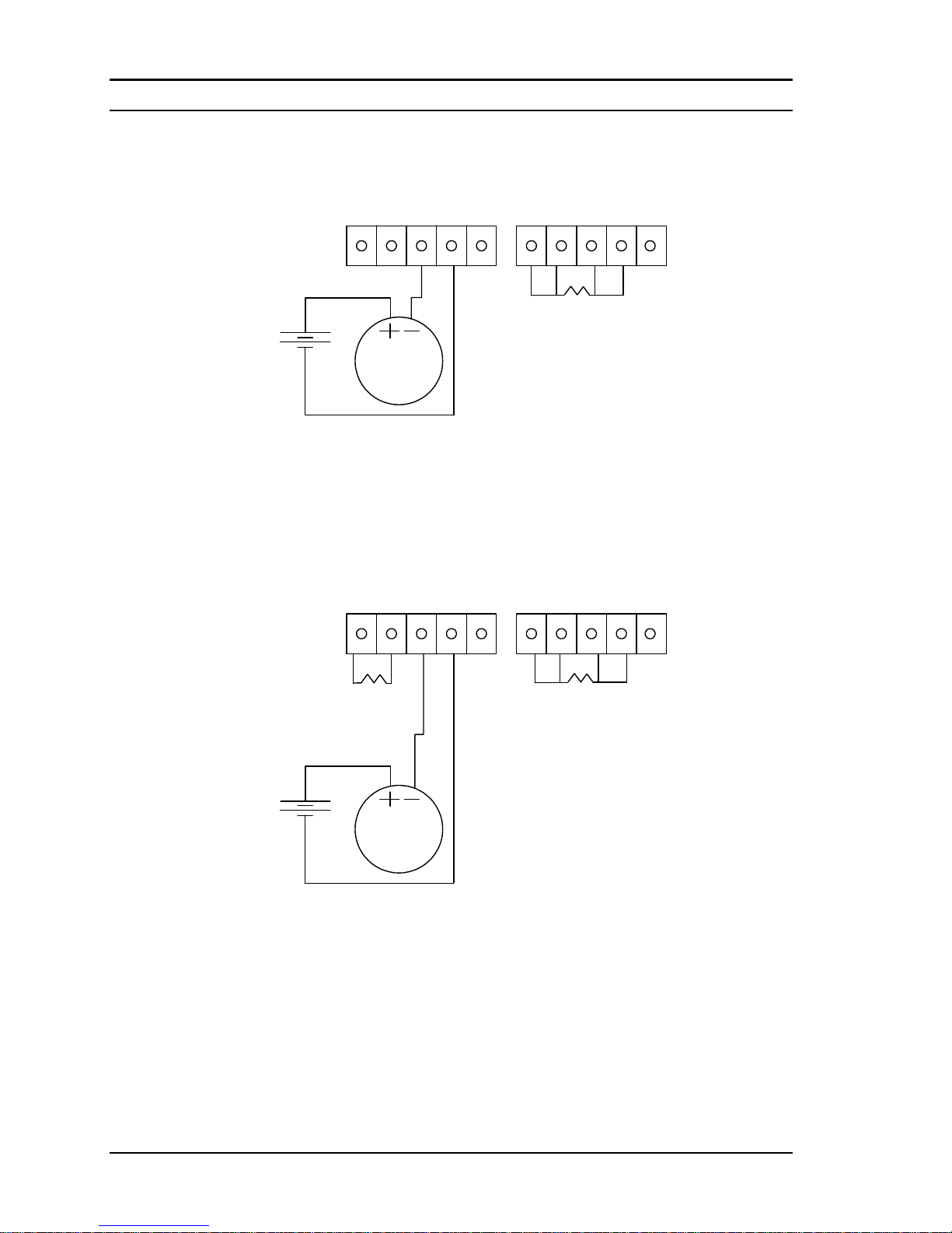
Chapter 2 Installation Series M22/M23/M24 Instruction Manual
2-38 M-000-00010
High Power
Option
2Option 1
1 2 3 4 5 1 2 3 4 5
Power
Ext. 4-20 mA
Input Device
External
+
-
R = 1000 ohm
Red
Red
Black Black
Figure 2-48. External 4-20 mA Input and RTD Wiring – High Power
Optional Energy EMS External 4-20 mA Input and RTD Wiring
R = 1000 ohm
Red
Red
Black Black
Option
2Option 1
1 2 3 4 5 1 2 3 4 5
Power
External
+
-
Ext. 4-20 mA
Input Device
R = 1000 ohm
Red
Black
Figure 2-49. Energy EMS External 4-20 mA Input and RTD Wiring – High Power
Page 59
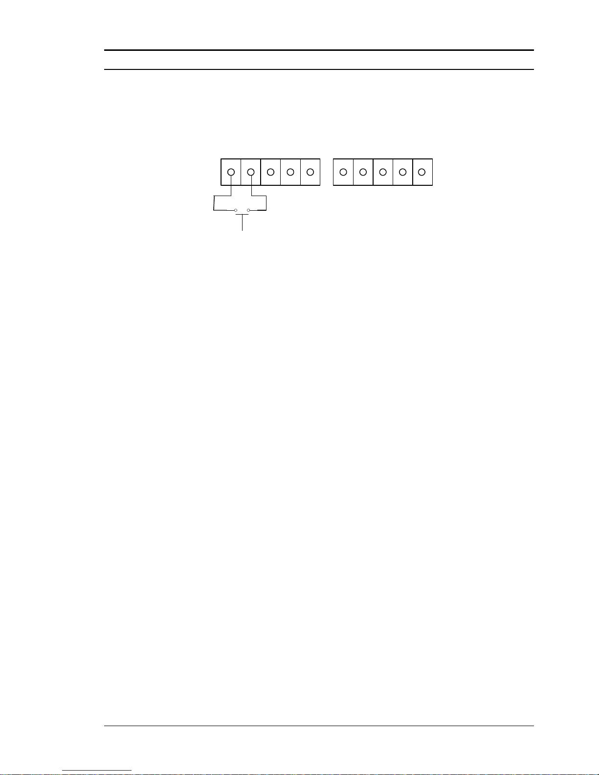
Series M22/M23/M24 Instruction Manual Chapter 2 Installation
M-000-00010 2-39
Optional External Contact Closure Input Wiring
Option 2Option 1
1 2 3 4 5 1 2 3 4 5
Figure 2-50. Optional External Contact Closure Input Wiring
Follow the above diagram to wire an external switch input into the flow
meter. The meter is configured to have Option 1 used for the external input. If the above switch is used to remotely reset the totalizer a pushbutton switch with a momentary contact closure is recommended.
Page 60

Chapter 2 Installation Series M22/M23/M24 Instruction Manual
2-40 M-000-00010
Page 61
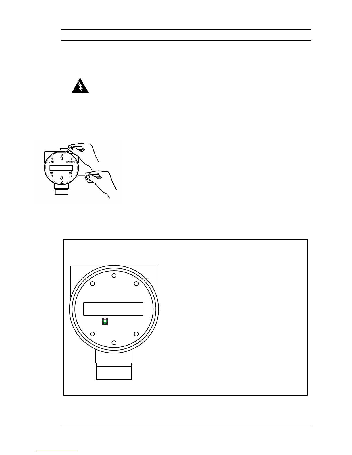
Series M22/M23/M24 Instruction Manual Chapter 3 Operation
M-000-00010 3-1
Chapter 3 Operating Instructions
After installing the Pro-V Vortex Flow Meter, you are ready to
begin operation. The sections in this chapter explain the display/keypad commands, meter start-up and programming. The
meter is ready to operate at start up without any special programming. To enter parameters and system settings unique to
your operation, see the following pages for instructions on using
the setup menus.
Flow Meter Display/Keypad
The flow meter’s digital electronics allow you to set, adjust and
monitor system parameters and performance. A full range of
commands are available through the display/keypad. The LCD
display gives 2 x 16 characters for flow monitoring and programming. The six push-buttons can be operated with the enclosure cover removed. Or, the explosion-proof cover can remain
in place and the keypad operated with a hand-held magnet positioned at the side of the enclosure as shown in the illustration at
the left. To secure the enclosure cover use a 1/16” hex key
wrench to tighten the 6-32 x 1/4 cup point socket set locking
screw.
From the Run Mode, the ENTER key allows
access to the Setup Menus (through a
password screen). Within the Setup Menus,
pressing ENTER activates the current field.
To set new parameters, press the ENTER key
until an underline cursor appears. Use the
keys to select new parameters.
Press ENTER to continue. (If change is not
allowed, ENTER has no effect.) All outputs
are disabled when using the Setup Menus.
The
keys advance through each screen
of the current menu. When changing a system
parameter, all
keys are available to enter
new parameters.
The EXIT key is active within the Setup Menus.
When using a Setup Menu, EXIT returns you to the
Run Mode. If you are changing a parameter and
make a mistake, EXIT allows you to start over.
Display/Keypad
Commands
EXIT ENTER
VorTek
INSTRUMENTS
Pro-V™
Figure 3-1. Flow Meter Display/Keypad
Warning!
Do not open covers when an ex-
plosive atmosphere may be pre-
sent.
VorTek
Instruments,
LLC
Pro-V
TM
Page 62
Chapter 3 Operation Series M22/M23/M24 Instruction Manual
3-2 M-000-00010
Display Contrast Adjustment
The flow meter display contrast is set at the factory but if the display characters appear too dark or too light proceed as follows:
1) Hold down the “Exit” button on the front panel for 5 to 10 sec-
onds. “Setting Contrast” will appear.
2) Push the “Up” arrow to darken the display or the “Down” arrow
to lighten it.
3 Push the “Enter” button to save the contrast setting.
Start-Up
To begin flow meter operation:
1. Verify the flow meter is installed and wired as described in Chapter 2.
2. Apply power to the meter. At start up, the unit runs a series of self-
tests that check the RAM, ROM, EPROM and all flow sensing components. After completing the self-test sequence, the Run Mode
screens appear.
3. The Run Mode displays flow information as determined by system
settings. Some screens depicted on the next page may not be displayed based on these settings. Press the arrow keys to view
the Run Mode screens.
4. Press the ENTER key from any Run Mode screen to access the Setup
Menus. Use the Setup Menus to configure the meter’s multiparameter features to fit your application.
Note
Starting the flow meter
or pressing EXIT will
always display the
Run Mode screens.
Page 63
Series M22/M23/M24 Instruction Manual Chapter 3 Operation
M-000-00010 3-3
Setup
Menus
Password
Mass Flow
Rate
Volume
Flow Rate
Temperature
Pressure
Density
Total
Alarm 1
Status
Fluid
ENTER
Date & Time
Alarm 2
Status
Alarm 3
Status
Run Mode
Screens
Energy
*
ENTER
Press Exit to return
to Run Mode
Use
keys to access
each item
*
Energy EMS
Meters Only
Page 64
Chapter 3 Operation Series M22/M23/M24 Instruction Manual
3-4 M-000-00010
Using the Setup Menus
Output
Menu
Display
Menu
Alarms
Menu
Totalizer #1
Menu
Fluid
Menu
Units
Menu
Time & Date
Menu
Diagnostics
Menu
Calibration
Menu
Password
Menu
Password
4-20 mA
ENTER
Output 2
Output 3
Modbus
Units
Cycle Time
(sec)
Number of
Digits
Display TC
(sec)
Mf Vf Te
Pr De T
A1 A2 A3
Fl Dt *E
Relay
Alarm 1
Relay
Alarm 2
Relay
Alarm 3
Alarm Log
Clear Alarm
Log
Totaling
Unit per
Pulse
Reset Total
Flowing
Fluid
STD Temp
(F)
STD Press
(PSIA)
NORM
Temp (C)
NORM
Press (KPA)
Mass Flow
Unit
Volume
Flow Unit
Temperature
Unit
Density
Unit
Pressure
Unit
Set Time
Set Date
Sim Vor
Freq
Sim Temp 1, 2
Sim Pressure
Highest
Velocity
Highest
Temp 1, 2
Highest
Pressure
Lowest
Int Temp
Meter Size
or Pipe ID
Base Kf
Base
Reynolds
Head
Diameter
Abs
Roughness
Set
Password
Mass Flow
Rate
Volume
Flow Rate
Temperature
Pressure
Density
Total
Alarm 1
Status
Fluid
ENTER
Date & Time
Alarm 2
Status
Alarm 3
Status
Run Mode
Screens
Setup Menus
Atm. Press
14.6959
Gauge
Pressure
(Abs/Gauge)
Baud Rate
Modbus
Order
Comm
Protocol
Totalizer #2
Menu
Totaling
Reset Total
Energy
Menu
Loc in Sent
Flow
Yes / No
Heating System
Yes / No
% Returned
Energy
*
*
*
*
Energy EMS
Meters Only
Address
Scaled
Frequency
Output 1
4-20 mA
4-20 mA
* Energy
Unit
System Log
Clear Sys
Log
Highest
Int Temp
Vortex Coef
Ck
Low Flow
Cutoff
Serial
Number
** BACnet
Device ID
** BACnet
MaxMaster
**
BACnet Meters Only
Page 65

Series M22/M23/M24 Instruction Manual Chapter 3 Operation
M-000-00010 3-5
Programming the Flow Meter
1. Enter the Setup Menu by pressing the ENTER key until prompted for a password. (All
outputs are disabled while using the Setup Menus.)
2. Use the keys to select the password characters (1234 is the factory-set
password). When the password is correctly displayed, press ENTER to continue.
3. Use the Setup Menus described on the following pages to customize the multi-
parameter features of your Pro-V Flow Meter. (The entire lower display line is
available for entering parameters.) Some items depicted in the graphic on the
preceding page may not be displayed based on flow meter configuration settings
4. To activate a parameter, press ENTER. Use the keys to make selections. Press
ENTER to continue. Press EXIT to save or discard changes and return to Run Mode.
5. Program the UNITS menu first because later menus will be based on the units
selected.
Page 66
Chapter 3 Operation Series M22/M23/M24 Instruction Manual
3-6 M-000-00010
Output Menu
Password
ENTER
Use
keys to access menus
Output
Menu
4-20 mA Output 1
More >
ENTER
Run Mode
*see below
*see below
4-20 mA Output 2
More >
***
see
below
***
see
below
4-20 mA Output 3
More >
***
see
below
< Measure >
None
Mass
Volume
Temp 1,2
Press
Density
***
Energy
< Measure >
None
Mass
Volume
Temp 1,2
Press
Density
***
Energy
< Measure >
None
Mass
Volume
Temp 1,2
Press
Density
***
Energy
< 4 mA = xxxx >
xxxx
< 4 mA = xxxx >
xxxx
< 4 mA = xxxx >
xxxx
< 20mA = xxxx >
xxxx
< 20mA = xxxx >
xxxx
< 20mA = xxxx >
xxxx
< Time Const (Sec)
xxxx
< Time Const (Sec)
xxxx
< Time Const (Sec)
xxxx
Modbus Order
0-1:2-3
1-0:3-2
2-3:0-1
Comm Protocol
Modbus RTU
(None1, None2,
Odd, Even)
Baud Rate
19200
Address
1
**see below
**see below
**see below
**see below
*
- Physical Layer not available on Two
Wire Mass – Accessible via HART
**
- Modbus not available on Two
Wire Mass
- Energy available on EMS meters only
***
Scaled Frequency
More >
Modbus Units
(Internal/Display)
**see below
< Max. Frequency >
xxxxx
< Measure >
None
Mass
Volume
Temp 1,2
Press
Energy
< 0 Hz = (units) >
xxxx
< Max Hz = (units) >
xxxx
< Time Const (Sec)
xxxx
3-2:1-0
Density
***
BACnet Device ID
xxx
****see below
- BACnet meters only
****
*****
- 10000 Hz maximum
*****
BACnet MaxMaster
xxx
****see below
Page 67

Series M22/M23/M24 Instruction Manual Chapter 3 Operation
M-000-00010 3-7
Example for Setting an Output
The following shows how to set Output 1 to measure mass flow with 4 mA = 0 lb/hr and 20 mA = 100 lb/hr with
a time constant of 5 seconds. (All outputs are disabled while using the Setup Menus.)
First, set the desired units of measurement:
1. Use keys to move to the Units Menu (see page 3-12).
2. Press key until Mass Flow Unit appears. Press ENTER.
3. Press key until lb appears in the numerator. Press key to move the underline cursor to the
denominator. Press the key until hr appears in the denominator. Press ENTER to select.
4. Press key until Units Menu appears.
Second, set the analog output:
1. Use keys to move to the Output Menu.
2. Press the key until 4-20 mA Output 1 appears.
3. Press key to access Measure selections. Press ENTER and press the key to select Mass. Press ENTER.
4. Press key to set the 4 mA point in the units you have selected for mass of lb/hr. Press ENTER and
use keys to set 0 or 0.0. Press ENTER.
5. Press key to set the 20 mA point. Press ENTER and use keys to set 100 or 100.0. Press ENTER.
6. Press key to select the Time Constant. Press ENTER and use keys to select 5. Press ENTER.
7. Press the EXIT key and answer YES to permanently save your changes.
Example for Calculating Output Current
Assume Output 1 is scaled as above for mass flow with 4 mA = 0 lb/hr and 20 mA = 100 lb/hr.
Output 1 current = ((Flow rate / 100) x 16 mA) + 4 mA
Page 68
Chapter 3 Operation Series M22/M23/M24 Instruction Manual
3-8 M-000-00010
Display Menu
Password
ENTER
Display
Menu
Cycle Time (sec)
0
ENTER
Run Mode
Number of Digits
2
MF Vf Te Pr De T
Y or N
A1 A2 A3 Fl Dt E
Y or N
If Cycle Time is set to zero, manual advance is required
Used to set the number of digits displayed after the decimal point
MF = Mass Flow
Vf = Volume Flow
Te = Temperature
Pr = Pressure
De = Density
T = Total
A1 = Alarm 1 Status
A2 = Alarm 2 Status
A3 = Alarm 3 Status
Fl = Fluid
Dt = Date and Time
For each parameter:
Select Yes to view parameter in Run Mode
Select No to hide parameter in Run Mode
Display TC (sec)
1
TC = Display Time constant, used to smooth display
*
E = Energy
*
Energy EMS Meters Only
Use
keys to access menus
Use the Display Menu to set the cycle time for automatic screen sequencing used in the Run
Mode, change the precision of displayed values, smooth the values or enable or disable each item
displayed in the Run Mode screens.
Example for Changing a Run Mode Display Item
The following shows how to remove the temperature screen from the Run Mode screens. Note: all outputs
are disabled while using the Setup Menus.
1. Use keys to move to the Display Menu.
2. Press key until Mf Vf Pr Te De T appears.
3. Press ENTER to select. Press key until the cursor is positioned below Te.
4. Press key until N appears. Press ENTER to select.
5. Press EXIT and then ENTER to save changes and return to the Run Mode.
Page 69
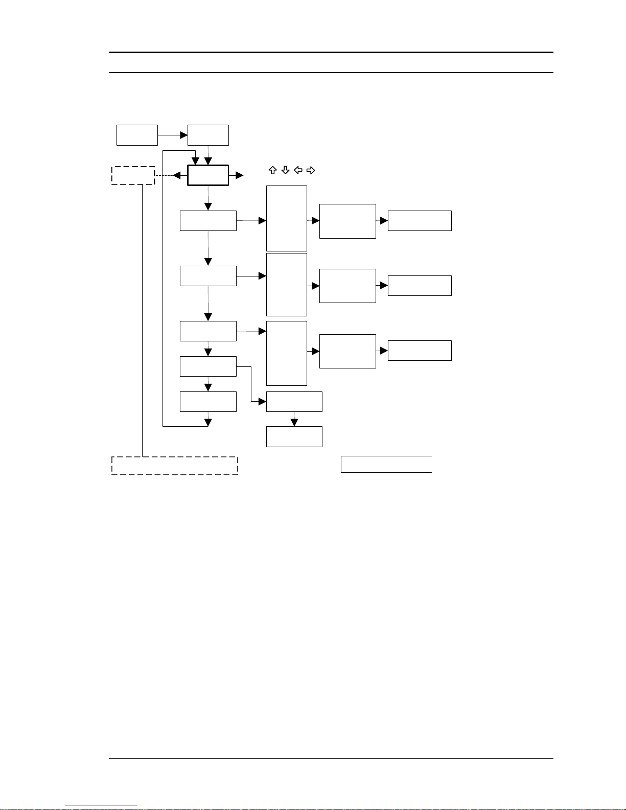
Series M22/M23/M24 Instruction Manual Chapter 3 Operation
M-000-00010 3-9
Alarms Menu
Password
ENTER
Use
keys to access menus
Alarms
Menu
Relay Alarm 1
More >
ENTER
Run Mode
Relay Alarm 2
More >
Relay Alarm 3
More >
Alarm LOG
xx Files (ENTER)
Clear Alarm LOG?
YES or NO
<Measure> units
xxxx
xxxx
xxxx
Alarm File
Time
Date
(Press EXIT to return
to Alarm LOG)
* see below
Physical Layer does not exist on Two Wire
Mass - Accessible via HART
<Measure>
None
Mass
Volume
Temp 1,2
Press
Density
**
Energy
<Measure>
None
Mass
Volume
Temp 1,2
Press
Density
**
Energy
<Measure>
None
Mass
Volume
Temp 1,2
Press
Density
**
Energy
<Mode>
None
HIGH Alarm (>)
LOW Alarm (<)
<Mode>
None
HIGH Alarm (>)
LOW Alarm (<)
<Mode>
None
HIGH Alarm (>)
LOW Alarm (<)
<Measure> units
<Measure> units
*
** Energy EMS Meters Only
Example for Setting an Alarm
The following shows how to set Relay Alarm 1 to activate if the mass flow rate is greater than 100 lb/hr. You can
check the alarm configuration in the Run Mode by pressing the keys until Alarm [1] appears. The lower line
displays the mass flow rate at which the alarm activates. Note: all outputs are disabled while using the Setup Menus.
First, set the desired units of measurement:
1. Use keys to move to the Units Menu (see to page 3-12).
2. Press key until Mass Flow Unit appears. Press ENTER.
3. Press key until lb appears in the numerator. Press key to move the underline cursor to the
denominator. Press the key until hr appears in the denominator. Press ENTER to select.
4. Press key until Units Menu appears.
Second, set the alarm:
1. Use keys to move to the Alarms Menu.
2. Press the key until Relay Alarm 1 appears.
3. Press key to access Measure selections. Press ENTER and use the key to select Mass. Press ENTER.
4. Press key to select the alarm Mode. Press ENTER and use key to select HIGH Alarm. Press ENTER.
5. Press key to select the value that must be exceeded before the alarm activates. Press ENTER and use
keys to set 100 or 100.0. Press ENTER.
6. Press the EXIT key to save your changes. (Alarm changes are always permanently saved.)
(Up to three relay alarm outputs are available depending on meter configuration.)
Page 70
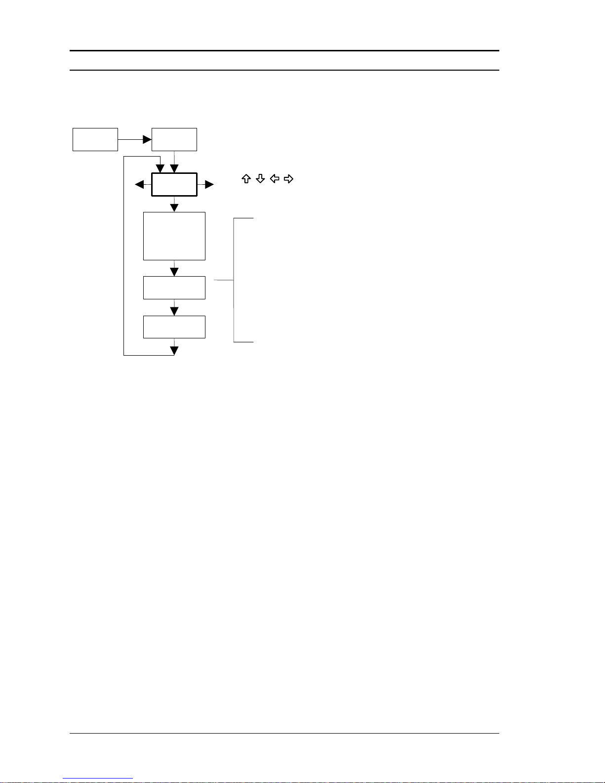
Chapter 3 Operation Series M22/M23/M24 Instruction Manual
3-10 M-000-00010
Totalizer #1 Menu
Password
ENTER
Use
keys to access menus
Totalizer
Menu
Totaling
Inactive
Mass
Volume
ENTER
Run Mode
(unit) / Pulse
xxxx
Reset Total ?
YES or NO
Example:
Maximum flow rate = 600 gallons per minute
(600 gallons per minute = 10 gallons per second)
If unit per pulse is set to 600 gallons per pulse,
the totalizer will pulse once every minute.
If unit per pulse is set to 10 gallons per pulse,
the totalizer will pulse once every second.
Energy
Use the Totalizer Menu to configure and monitor the totalizer. The totalizer maximum count is
999,999,999 at which point it will roll over to 0. The totalizer output is a 50 millisecond (.05 second)
positive pulse (relay closed for 50 milliseconds). The totalizer cannot operate faster than one pulse
every 100 millisecond (.1 second). A good rule to follow is to set the unit per pulse value equal to the
maximum flow in the same units per second. This will limit the pulse to no faster than one pulse
every second.
Example for Setting the Totalizer
The following shows how to set the totalizer to track mass flow in kg/sec. (All outputs are disabled while using
the Setup Menus.)
First, set the desired units of measurement:
1. Use keys to move to the Units Menu (see to page 3-12).
2. Press key until Mass Flow Unit appears. Press ENTER.
3. Press key until kg appears in the numerator. Press key to move the underline cursor to the
denominator. Press the key until sec appears in the denominator. Press ENTER to select.
4. Press key until Units Menu appears.
Second, set the pulse output:
1. Use keys to move to the Totalizer Menu.
2. Press the key until Totaling appears.
3. Press ENTER and press the key to select Mass. Press ENTER.
4. Press key to set the pulse output in the units you have selected for mass flow of kg/sec. Press
ENTER and use keys to set the pulse value equal to the maximum flow in the same units per
second. Press ENTER.
5. To reset the totalizer, press key until Reset Total? appears. Press ENTER and the key to reset the
totalizer if desired. Press ENTER.
6. Press the EXIT key and answer YES to permanently save your changes.
Page 71
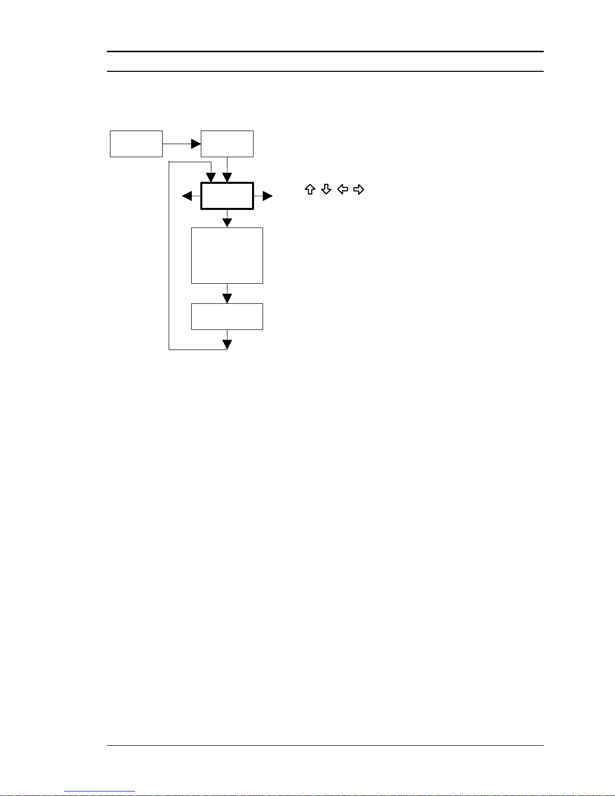
Series M22/M23/M24 Instruction Manual Chapter 3 Operation
M-000-00010 3-11
Totalizer #2 Menu
Password
ENTER
Use
keys to access menus
Totalizer
Menu
ENTER
Run Mode
Totaling
Inactive
Mass
Volume
Energy
Reset Total ?
YES or NO
Use the Totalizer #2 to Monitor Flow or Energy. The totalizer maximum count is 999,999,999 at
which point it will roll over to 0. Note that Totalizer #2 does not operate a relay, it is for monitoring
only.
Page 72
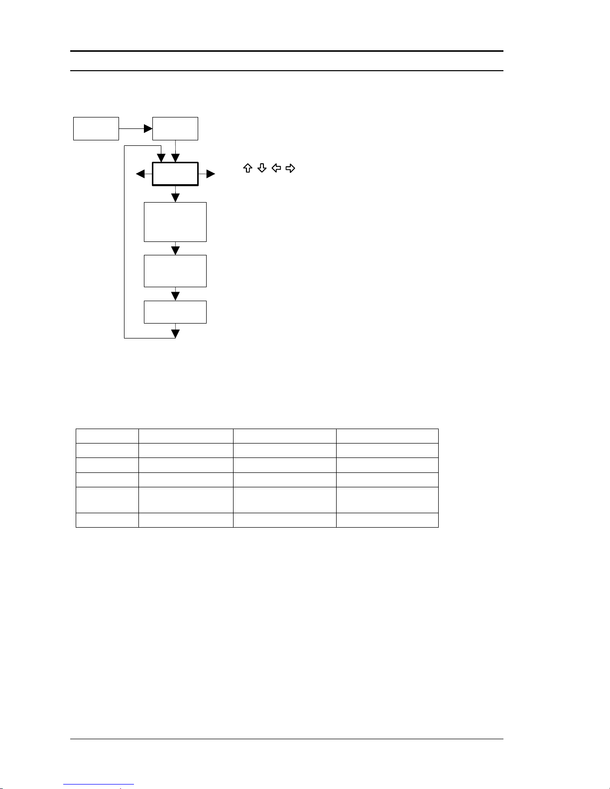
Chapter 3 Operation Series M22/M23/M24 Instruction Manual
3-12 M-000-00010
Energy Menu – For EMS Energy Meters Only
Password
ENTER
Use
keys to access menus
Energy
Menu
Loc in Sent
Flow
Yes or No
ENTER
Run Mode
Heating
System
Yes or No
% Returned
xxx
Configuration:
There are several possibilities regarding the measurement of water or steam energy given the location
of the meter and the use of a second RTD. The table below summarizes the possibilities:
Fluid
Meter Location
Second RTD
Measurement
Water
“Sent” Flow Line
“Return Flow Line
Change in Energy
Water
“Return” Flow Line
“Sent” Flow Line
Change in Energy
Water
“Sent” Flow Line
None
Outgoing Energy
Steam
“Sent” Flow Line
“Return” Flow Line
(condensate)
Change in Energy
Steam
“Sent” Flow Line
None
Outgoing Energy
As above, you must properly configure the meter in the Energy Menu.
1. Loc in Sent Flow? Select Yes or No based on where the meter is located. Refer to the above
table
2. Heating System? Select Yes for a hot water system used for heating. Select No for a chilled
water system used for cooling. Always select Yes for a steam system.
3. % Returned. Select a number between 0% and 100%. Estimate the amount of water that returns.
It is usually 100%, or can be less than 100% if historical data shows the amount of makeup water
used. If a second RTD is not used, set to 0%. When 0% is selected, the energy calculation
represents the outgoing energy only (no return energy is subtracted). NOTE: the meter ships
from the factory assuming 0% return and has a 1000 ohm resistor installed in the RTD #2
wiring location. This needs to be removed if the meter is to be used in a manner other than
with 0% return and with the customer supplied RTD in its place.
Page 73
Series M22/M23/M24 Instruction Manual Chapter 3 Operation
M-000-00010 3-13
Fluid Menu
Password
ENTER
Fluid
Menu
Flowing Fluid
Liquids >
Goyal-Dorais >
API 2540 >
Nat Gas AGA8 >
Real Gas >
Other Gas >
ENTER
Run Mode
Other Liquids >
Liquified Gas >
Use
keys to access menus
< Liquid
Water
Ammonia
Chlorine
< Density >
xxxx
< AL >
xxxx
< BL
xxxx
< Mole Weight >
xxxx
< CRIT PRESS >
xxxx
< CRIT TEMP >
xxxx
< CRIT Z >
xxxx
< AL >
xxxx
< BL
xxxx
< Density @ 60F >
xxxx
< K0 >
xxxx
< K1 >
xxxx
< AL >
xxxx
< BL
xxxx
< Specific Gravity >
xxxx
< MoleFract N2 >
xxxx
<MoleFract CO2>
xxxx
<Ref Temp(F)>
xxxx
< Ref Press(PSIA)
xxxx
< Real Gas
Steam T & P Comp
Air
Argon
Ammonia
CO
CO2
Helium
Hydrogen
Methane
Nitrogen
Oxygen
Select “Steam T & P Comp” for VT and
in the run mode screens.
“Sat Steam T Comp” for the fluid type
VTP models. The VT model will display
For a V model in any fluid, enter nominal operating temperature and
pressure as simulated values in the diagnostics menu.
Propane
STD Press (PSIA)
xxxx
NORM Temp (C)
xxxx
NORM Press (KPA)
xxxx
STD Temp (F)
xxxx
Thermal Oil >
Ethylene Glycol >
< Specific Gravity >
xxxx
< Compress (Z) >
xxxx
< Viscosity
xxxx
< Liquified Gas
Carbon Dioxide
Nitrogen
Hydrogen
Oxygen
Argon
< Thermal Oil
Paratherm
Therminol VP-1
Dowtherm A
< % Volume @ 68 Deg. F
xx
Use the Fluid Menu to configure the flow meter for use with common gases, liquids and steam. Your
flow meter is pre-programmed at the factory for your application’s process fluid.
Reference Richard W. Miller, Flow Measurement Engineering Handbook (Third Edition, 1996),
page 2-75 for definition and use of the Goyal-Doraiswamy equation and page 2-76 for the
definition and use of the API 2540 equation. Also, see Appendix C for Fluid Calculation
equations.
The units of measurement used in the Fluid Menu are preset and are as follows:
Mole Weight = lbm/(lbm·mol), CRIT PRESS = psia, CRIT TEMP = °R, Density = lbm/ft3 and
Viscosity = cP (centipoise).
Page 74
Chapter 3 Operation Series M22/M23/M24 Instruction Manual
3-14 M-000-00010
Units Menu
Energy Unit
BTU, MBTU, MMBT, MWHr
Password
ENTER
Use
keys to access menus
Units
Menu
Mass Flow Unit
lb, Ston, Lton, gram
kg, Mton, scf, nm3
/
ENTER
Run Mode
Ston = Short Ton = 2000 lb
Lton = Long Ton = 2240 lb
Mton = Metric Ton = 1000 kg
sec, min, hr, day
Volume Flow Unit
gal, MilG, ImpG, bbl
lit, MilL, m3, ft3
Temperature Unit
Deg F, Deg C, Kelvin, Rankine
Pressure Unit
psi, inH2O, ftH2O, mmH2O, in HG,
mmHG, ATM, Bar, mBar, gm/cm2, kg/cm2,
Pascal, KiloPa, MegaPa, Torr, 4inH20, 4mmH2O
Density Unit
lbm/ft3, kg/m3, gm/cc, lbm/gal,
gm/mlit, kg/lit, gm/lit, lbm/in3
MilG = Million gallons
= Imperial gallon = 1.20095 US gallons
bbl = barrels = 42 US gallons
MilL = Million liters
4inH2O and 4mmH2O are based on
water at 4 degrees C.
Gauge Pressure Unit
Absolute / Gauge
Transducer reads in Absolute – if Gauge is desired
then atmospheric pressure at meter is needed
Atm. Pressure
14.6959
Menu is only activated if Gage Pressure is chosen
Enter the value in PSIA
ImpG
/
sec, min, hr, day
kWHr, HPHr, MCal,MJ
/
sec, min, hr, day
MBTU = Thousand BTU
MMBTU = Million BTU
Use the Units Menu to configure the flow meter with the desired units of measurement. (These
are global settings and determine what appears on all screens.
Page 75
Series M22/M23/M24 Instruction Manual Chapter 3 Operation
M-000-00010 3-15
Time & Date Menu
Password
ENTER
Use
keys to access menus
Time & Date
Menu
Set Time
xx:xx:xx
ENTER
Run Mode
Set Date
xx/xx/xx
Use the Time and Date Menu to enter the correct time and date into the flow meter’s
memory. The parameters are used in the Run Mode and the alarm and system log
files.
Note: Time is displayed in AM/PM format, but military format is used to set the time.
For example, 1:00 PM is entered as 13:00:00 in the Set Time menu.
Example for Setting the Time
How to set the time to 12:00:00. You can check the time in the Run Mode by pressing the keys
until the Time & Date screen appears. Note: all outputs are disabled while using the Setup Menus.
1. Use keys to move to the Time and Date Menu.
2. Press key until Set Time appears. Press ENTER.
3. Press key until 1 appears. Press key to move the underline cursor to the next digit.
Press the key until 2 appears. Continue sequence until all desired parameters are entered. Press ENTER to return to the Time and Date Menu.
4. Press EXIT to return to the Run Mode.
Page 76
Chapter 3 Operation Series M22/M23/M24 Instruction Manual
3-16 M-000-00010
Diagnostics Menu
Password
ENTER
Use
keys to access menus
Diagnositcs
Menu
Sim Vor Freq
xxx
ENTER
Run Mode
Sim Temp 1, 2
xxx
Sim Pressure
xxx
Highest Velocity
xxx
Highest Temp 1, 2
xxx
Highest Pressure
xxx
System LOG
xx Files (ENTER)
Clear Sys LOG?
YES or NO
SysLog File #xx System Log File
Time
Date
Press EXIT to return
to System LOG
Momentarily displayed
Use Left and Right
arrows to access all
system log files
Simulate Vortex
Frequency (Hz)
* Simulate Temperature
* Simulate Pressure
Highest Recorded
Velocity
Highest Recorded
Temperature
Highest Recorded
Pressure
Highest Int Temp
xx
Lowest Int Temp
xx
Highest Electronics
Temperature
Lowest Electronics
Temperature
For a V model in any fluid, enter nominal operating temperature and
pressure as simulated values in the diagnostics menu.
* The unit of measure of the displayed value is the
same as the unit configured for the flow meter.
For a VT model in any fluid except steam, enter nominal operating
pressure as a simulated value in the diagnostics menu.
Use the Diagnostics Menu to simulate operation and review the system files. The system log files
contain time/date stamped messages including: power on, power off, programming time outs,
parameter faults, incorrect password entry and other various information relative to system
operation and programming.
The simulated inputs are for testing the meter to verify that the programming is correct. They are
also used to enter nominal operating temperature and pressure for the V only model. Simulated
vortex frequency allows you to enter any value for the sensor input in Hz. The meter will
calculate a flow rate based on the corresponding value and update all analog outputs (the
totalizer display and output is not affected by a simulated frequency). The simulated pressure
and temperature settings work the same way. The meter will output these new values and will use
them to calculate a new density for mass flow measurement. Note: when your diagnostic work is
complete, make sure to return the values to zero to allow the electronics to use the actual
transducer values. For the V only model keep the temperature and pressure at nominal operating
conditions.
Page 77
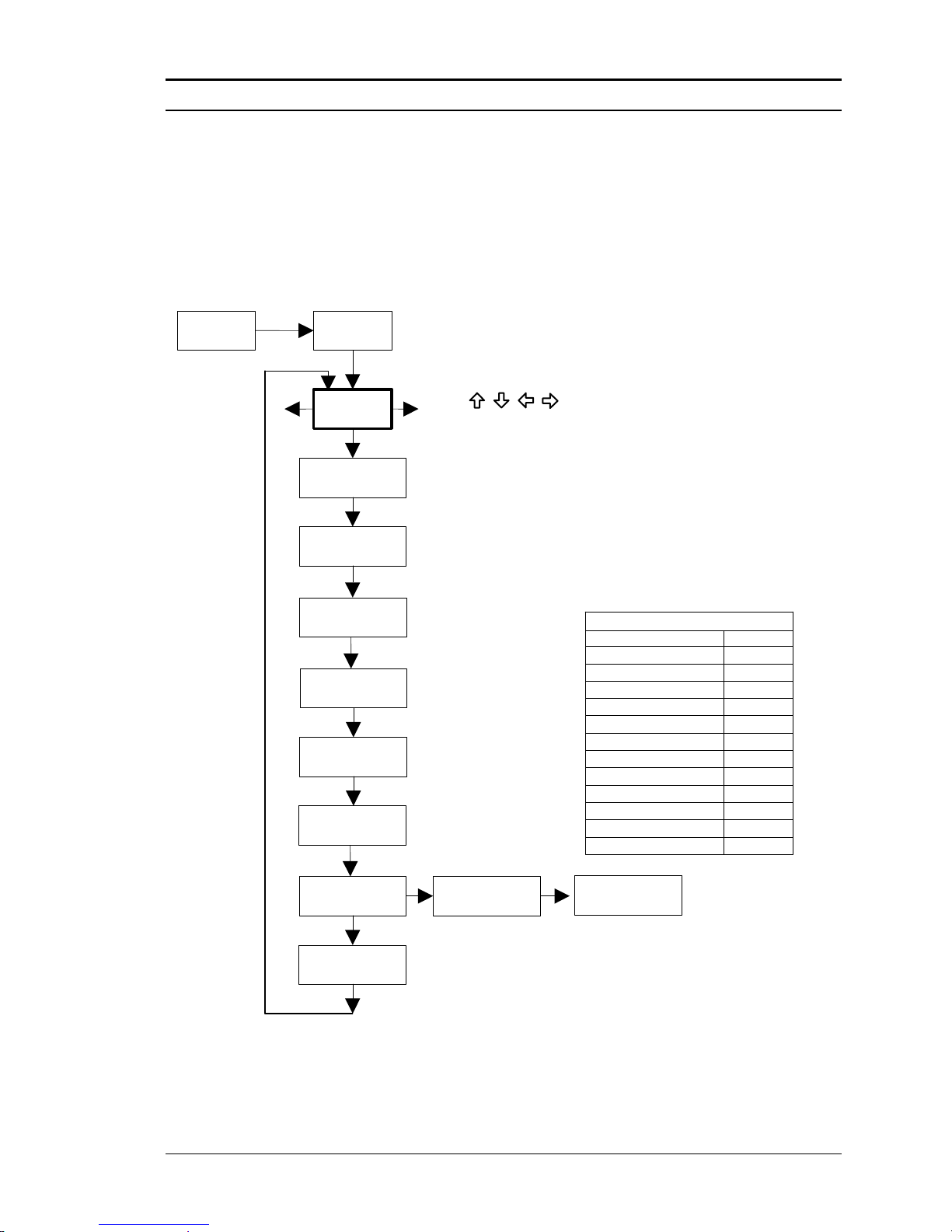
Series M22/M23/M24 Instruction Manual Chapter 3 Operation
M-000-00010 3-17
If the meter display indicates a temperature or pressure fault, a substitute value can be entered to
allow flow calculations to continue at a fixed value until the source of the fault is identified and
corrected. The units of measure of the displayed values are the same as the units configured for
the flow meter.
Calibration Menu
Password
ENTER
Use
keys to access menus
Calibration
Menu
Meter Size
or Pipe ID
ENTER
Run Mode
Base Kf
xx.xxx
Vortex Coef Ck
xx
Low Flow Cutoff
xx
Serial Number
xxxxxxxxx
Inline style meter – meter size
Insertion style meter – pipe internal diameter (inches)
Meter calibration constant
Inline style meter – pulses / ft
3
Insertion style meter – pulses / ft
Adaptive filter setting
Low Flow Cutoff
setting displayed
in volumetric flow
units (view only)
< Vol (xxx/xxx) >
xxx
< Mass (xxx/xxx)
xxx
Low Flow Cutoff
setting displayed
in mass flow
units (view only)
Base Reynolds
xxxx.xx
Head Diameter in.
x.xxx
Abs Roughness in.
x.xxxx
Meter calibration constant
ID of insertion head
Pipe roughness
Roughness
Typical Surface Roughness (inches)
Type of Pipe
Steel, severely corroded
Steel, drawn, new
Steel, welded, new
Steel, galvanized, new
Steel, lightly corroded
Steel, light scaling
Steel, heavy scaling
Steel, sheet, smooth
Cast Iron, new
Cast Iron, corroded
Cast Iron, with scaling
Drawn Tubing, plastic
0.0024
0.003
0.0028
0.006
0.01
0.068
0.05
0.11
0.025
0.06
0.1
0.00006
Default value = 0.003
The Calibration Menu contains the calibration coefficients for the flow meter. These values
should by changed only by properly trained personnel. The Vortex Coef Ck and Low Flow Cutoff
are set at the factory. Consult the factory for help with these settings if the meter is showing
erratic flow rate.
Page 78
Chapter 3 Operation Series M22/M23/M24 Instruction Manual
3-18 M-000-00010
Password Menu
Password
ENTER
Use
keys to access menus
Password
Menu
Set Password
1234
ENTER
Run Mode
Use the Password Menu to set or change the system password. The factory-set password
is 1234.
Page 79
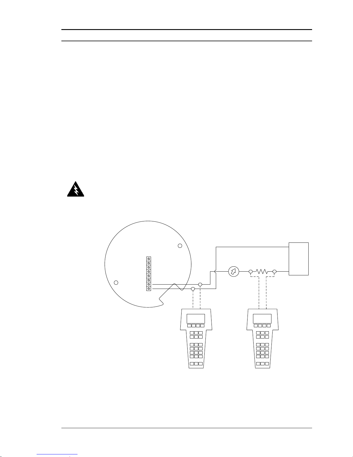
Series M22/M23/M24 Instruction Manual Chapter 4 Serial Communications
M-000-00010 4-1
Chapter 4 Serial Communications
HART Communications
The HART Communications Protocol (Highway Addressable Remote Transducer Protocol) is a bidirectional digital serial communications protocol. The
HART signal is based on the Bell 202 standard and is superimposed on 4-20 mA
Output 1. Peer-to-peer (analog / digital) and multi-drop (digital only) modes are
supported.
Wiring
The diagrams below detail the proper connections required for HART
communications:
Loop Powered Meter Wiring
LOOP
POWER
+ -
FREQ
OUT
PULSE
OUT
-- + +
OPTIONAL
BACKLIGHT
POWER
+ -
R load,
250 ohm
minimum
+
_
DC
Power
Supply
Remote Connection
for Communicator
Current
Meter
Field Connection
for Communicator
Vortex Meter
Figure 4-1.Loop Powered Meter Wiring (HART)
Warning!
Place controls in manual
mode when making
configuration changes to
the vortex meter.
Page 80
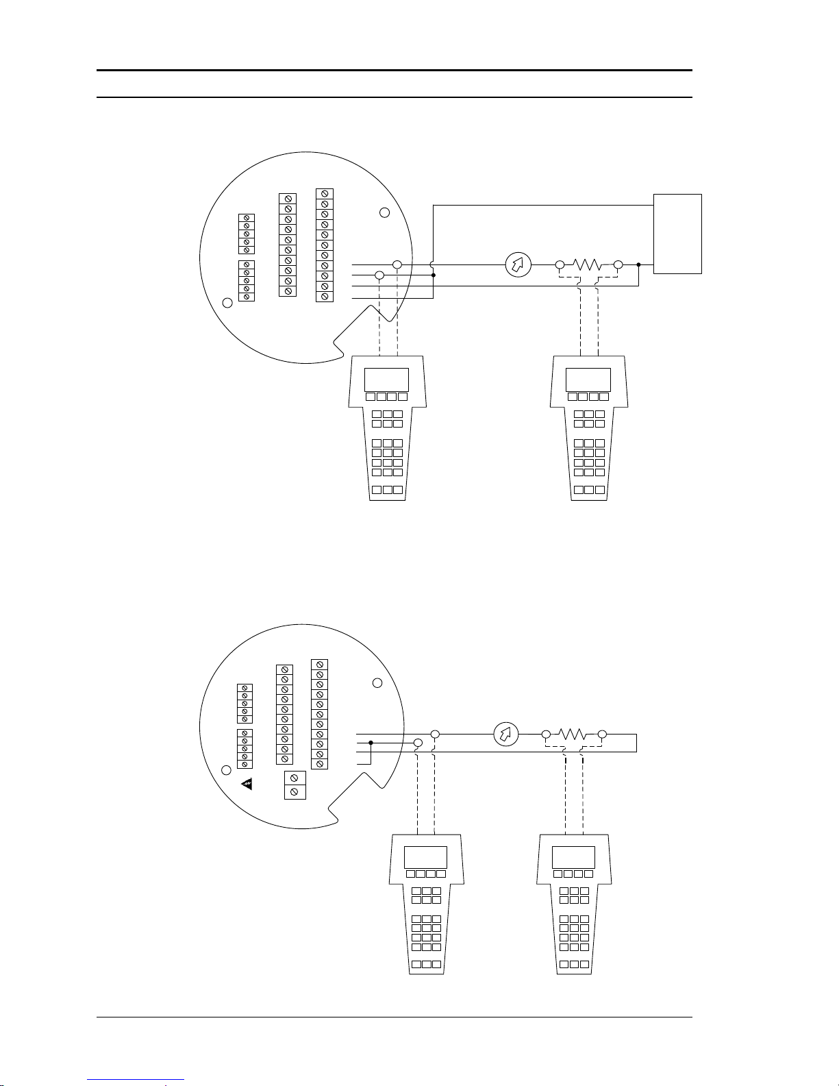
Chapter 4 Serial Communications Series M22/M23/M24 Instruction Manual
4-2 M-000-00010
DC Powered Meter Wiring
R load,
250 ohm
minimum
+
_
DC
Power
Supply
Remote Connection
for Communicator
Field Connection
for Communicator
Current
Meter
Vortex Meter
4-20
mA 3
4-20
mA 1
DC PWR
+ - +
4-20
mA 2
- + - +
RS485
RS485
RS485 GND
-
OPTION 2
+
ALARM
2
PULSE
OUT
FREQ
OUT
+ - +
ALARM
1
-+ -
4
OPTION 1
1 2 3 15 2 3
ALARM
3
- + -
4 5
+
-
Figure 4-2.DC Powered Meter Wiring (HART)
AC Powered Meter Wiring
R load,
250 ohm
minimum
Remote Connection
for Communicator
Field Connection
for Communicator
Current
Meter
Vortex Meter
4-20
mA 3
AC
PWR
IN
4-20
mA 1
24
VDC
OUT
+ - +
4-20
mA 2
- + - +
RS485
RS485
RS485 GND
-
OPTION 2
+
ALARM
2
HOT / L1
PULSE
OUT
NEUT / L2
FREQ
OUT
+ - +
ALARM
1
-+ -
4
OPTION 1
1 2 3 15 2 3
ALARM
3
- + -
4 5
+
-
Figure 4-3.AC Powered Meter Wiring (HART)
Page 81
Series M22/M23/M24 Instruction Manual Chapter 4 Serial Communications
M-000-00010 4-3
HART Commands with the DD Menu
Online Menu
1 Process Variables
2 Device Setup
3 Maintenance
4 Diagnostics
1 Enter Password
2 Display Unit
3 Analog Output
4 External Loop
5 Meter Display
6 Alarm Setup
7 Totalizer
8 Fluid Menu
9 Energy Setup
Device Menu
Sensor Cal
Review
1 Mass flo unit
2 Vol unit
3 Temp unit
4 Energy flo unit
5 Line pres unit
6 Dens unit
7 Totalizer units
8 Std & Norm Cond
1 Disp Cycle
2 Disp Digits
3 Disp Damping
4 Init Displ.
5 Disp Show/Hide
1 Alarm Status
2 Alarm 1 Setup
3 Alarm 2 Setup
4 Alarm 3 Setup
5 Records in Log
6 Read Alarm Log
7 Alarm Log Clear
1 Total
2 Totalize
3 Amount/Pulse
4 Total 2
5 Totalize 2
6 Clear Totalizer
1 Mass Flo
2 Vol
3 Temp
4 Temp 2
5 Delta Temp.
6 Energy flo
7 Pres
8 Dens
9 Total
Total 2
1 Alarm 1 var
2 Alarm 1 typ
3 Alarm 1 set pt
1 Alarm 2 var
2 Alarm 2 typ
3 Alarm 2 set pt
1 Alarm 3 var
2 Alarm 3 typ
3 Alarm 3 set pt
1 Norm Temp
2 Norm Press
3 Std Temp
4 Std Press
To Analog Output Menu
To Fluid Menu
1 External Input
2 Ext. Loop Zero Value
3 Ext. Loop Full Scale
4 Ext. Loop Zero Count
5 Ext. Loop Span Count
6 Set Ext. 4 mA
7 Set Ext. 20 mA
Inactive
Temp1
Temp 2
Pressure
1 Meter Location
2 Heating or Cooling
3 % Return
To Sensor Cal Menu
To Review Menu
To Maintenance Menu
1 Date
2 Change Password
3 Line size
4 Meter size
5 Dev id
6 Tag
7 Descriptor
8 Message
9 Final asmbly num
Poll addr
Num req preams
Config Code
Compile Date
Compile Time
Signal Board Version
Hardware rev
Software rev
Master reset
To Diagnostics Menu
To Enter Password Menu
Page 82
Chapter 4 Serial Communications Series M22/M23/M24 Instruction Manual
4-4 M-000-00010
HART Commands with the DD Menu Continued
1 Fix Analog Output
2 Trim Analog Output
3 Configure AO1
4 PV is
5 PV AO1 Out
6 PV % range
7 Configure AO2
8 SV is
9 SV AO2 Out
SV % range
Configure AO3
TV is
TV AO3 Out
TV % range
Configure AO4
QV is
QV AO4 Out
QV % range
1 PV is
2 PV AO1 Out
3 PV
4 PV % range
5 Apply values
6 PV Range unit
7 PV LRV
8 PV URV
9 PV AO1 Lo end pt
PV AO1 Hi end pt
PV AO1 Added damp
1 SV is
2 SV AO2 Out
3 SV
4 SV % range
5 Apply values
6 SV Range unit
7 SV LRV
8 SV URV
9 SV AO2 Lo end pt
SV AO2 Hi end pt
SV AO2 Added damp
1 TV is
2 TV AO3 Out
3 TV
4 TV % range
5 Apply values
6 TV Range unit
7 TV LRV
8 TV URV
9 TV AO3 Lo end pt
TV AO3 Hi end pt
TV AO3 Added damp
1 QV is
2 QV AO4 Out
3 QV
4 QV % range
5 QV Range unit
6 QV LRV
7 QV URV
8.QV AO4 Lo end pt
9 QV AO4 Hi end pt
QV AO4 Added damp
From Online Menu
Analog Output Menu
Page 83
Series M22/M23/M24 Instruction Manual Chapter 4 Serial Communications
M-000-00010 4-5
HART Commands with the DD Menu Continued
1 Analog output
2 External Loop
3 Vortex Cal
From Online Menu
Maintenance Menu
1 Fix analog output
2 Trim analog output
1 External Input
2 Ext. Loop Zero Value
3 Ext. Loop Full Scale Value
4 Ext. Loop Zero Count
5 Ext. Loop Span Count
6 Set Ext. 4 mA
7 Set Ext. 20 mA
1 Ck Value
2 Low flow cutoff
3 Auto Set Ck
4 Auto Set LFC
1 Fluid
2 Fluid Type
Water
Ammonia
Chlorine
From Online Menu
Fluid Menu
Liquid
Other Liquid
Goyal-Dorais
API-2540
Nat Gas AGA8
Real Gas
Other Gas
Liquified Gas
Thermal Oil
Ethylene Glycol
Other Liquid Density
Viscosity Coef AL
Viscosity Coef BL
Mol Weight
Crit Press
Crit Temp
Crit Z
AL
BL
Density @ 60F
API K0
API K1
API AL
API BL
AGA Ref Temp
AGA Ref Press
Specific Gravity
Mole Fract N2
Mole Fract CO2
Steam
Air
Argon
Ammonia
CO
CO2
Helium
Hydrogen
Methane
Nitrogen
Oxygen
Propane
Specific gravity
Compress
Viscosity
Carbon Dioxide
Nitrogen
Hydrogen
Oxygen
Argon
Page 84
Chapter 4 Serial Communications Series M22/M23/M24 Instruction Manual
4-6 M-000-00010
HART Commands with the DD Menu Continued
1 Vel
2 Pres
3 Temp
4 Temp 2
5 Internal Temp
6 Vortex Diag.
7 Press Diag.
8 Temp Diag.
9 Int Temp Diag
Log
Status
1 Vtx Freq
2 Sim Vtx Freq
3 Vtx AtoD
4 Filter Set
5 Change Filter Set
6 High Pass Filter
7 Gain Set
8 Change Gain Set
9 Re
Vel
Max Vel
AD1
AD2
AD3
AD4
Ck
Level
From Online Menu
Diagnostics Menu
1 Model
2 Distributor
3 Write protect
4 Manufacturer
5 Dev id
6 Tag
7 Descriptor
8 Message
9 Date
Final asmbly num
Universal rev
Fld dev rev
Software rev
Poll addr
Num req preams
From Online Menu
Review Menu
1 Press
2 Sim Press
3 Excite
4 Excite AtoD
5 Sense
6 Sense AtoD
7 Max Press
1 Temp
2 Sim Temp
3 RTD1
4 RTD1 AtoD
5 Max temp
6 Temp 2
7 Sim Temp 2
8 RTD2
9 RTD2 AtoD
Max temp 2
1 Status group 0
2 Status group 1
3 Status group 2
SPI not communicating
Freq. Input Overrange
FRAM CRC error
Signal Board Power ...
RTD1 Fault
RTD2 Fault
Press. Transducer Fault
Totalizer Relay Overrange
Alarm 1 Set
Alarm 2 Set
Alarm 3 Set
1 Internal Temp (F)
2 Internal Temp (C)
3 Int. Max temp
4 Int. Min temp
1 Records in Log
2 Read System Log
3 System Log Clear
Page 85
Series M22/M23/M24 Instruction Manual Chapter 4 Serial Communications
M-000-00010 4-7
HART Commands with the DD Menu Continued
1 Calibration Review
2 Vortex Sensor
3 Vortex Cal
4 Press Sensor
5 Press Cal
6 Temp Sensor
7 Temp 1 & 2 Cal
8 Temp 2 Sensor
9 Cal. Correction
1 Vol unit
2 USL
3 LSL
4 Min Span
5 Snsr s/n
6 Sim Vtx freq
7 Max Vel
8 Vortex Diag
1 K Factor
2 Base Reynolds *
2 Ck Value
3 Low flow cutoff
4 Auto Set Ck
5 Auto Set LFC
1 Vtx Freq
2 Sim Vtx Freq
3 Vtx AtoD
4 Filter Set
5 Change Filter Set
6 High Pass Filter
7 Gain Set
8 Change Gain Set
9 Re
Vel
Max Vel
AD1
AD2
AD3
AD4
Ck
Level
From Online Menu
Sensor Cal Menu
1 Flow 1
2 Deviation 1
3 Flow 2
4 Deviation 2
5 Flow 3
6 Deviation 3
7 Flow 4
8 Deviation 4
9 Flow 5
Deviation 5
Flow 6
Deviation 6
Flow 7
Deviation 7
Flow 8
Deviation 8
Flow 9
Deviation 9
Flow 10
Deviation 10
1 Line pres unit
2 USL
3 LSL
4 Min span
5 Snsr s/n
6 Sim Press
7 Max Press
8 Press Diag
1 PCal B00
2 PCal B01
3 PCal B02
4 PCal B10
5 PCal B11
6 PCal B12
7 PCal B20
8 PCal B21
9 PCal B22
Ref. Resistance
Internal Temp. Cal
Cal Current
1 Temp unit
2 USL
3 LSL
4 Min span
5 Snsr s/n
6 Sim Temp
7 Max Temp
8 Temp Diag
1 RTD1 Ro
2 RTD1 alpha
3 RTD1 beta
4 RTD2 Ro
5 RTD2 alpha
6 RTD2 beta
1 Press
2 Sim Press
3 Excite
4 Excite AtoD
5 Sense
6 Sense AtoD
7 Max Press
1 Temp
2 Sim Temp
3 RTD1
4 RTD1 AtoD
5 Max Temp
6 Temp 2
7 Sim Temp 2
8 RTD2
9 RTD2 AtoD
Max temp 2
1 Temp unit
2 USL
3 LSL
4 Min span
5 Sim Temp 2
6 Max Temp 2
7 Temp Diag
1 Temp
2 Sim Temp
3 RTD1
4 RTD1 AtoD
5 Max Temp
6 Temp 2
7 Sim Temp 2
8 RTD2
9 RTD2 AtoD
Max temp 2
1 K Factor
2 Base Reynolds *
2 Ck Value
3 Low flow cutoff
4 RTD1 R0
5 RTD1 alpha
6 RTD1 beta
7 RTD2 R0
8 RTD2 alpha
9 RTD2 beta
Pcal B00, Pcal B01
Pcal B02, Pcal B10
Pcal B11, Pcal B12
Pcal B20, Pcal B21
Pcal B22
Ref. Resistance
Internal Temp. Cal
Cal current
Flow 1
Deviation 1
Flow 2
Deviation 2
Flow 3
Deviation 3
Flow 4
Deviation 4
Flow 5
Deviation 5
Flow 6
Deviation 6
Flow 7
Deviation 7
Flow 8
Deviation 8
Flow 9
Deviation 9
Flow 10
Deviation 10
Ext. Loop Zero Count
Ext. Loop Span Count
* If insertion vortex
Page 86
Chapter 4 Serial Communications Series M22/M23/M24 Instruction Manual
4-8 M-000-00010
HART Commands with Generic DD Menu
Online Menu
1 Device setup
2 PV
3 PV Loop current
4 PV LRV
5 PV URV
1 Process Variables
2 Diag/Service
3 Basic Setup
4 Detailed Setup
5 Review
1 PV
2 PV % Rnge
3 PV Loop current
1 Distributor
2 Model
3 Dev id
4 Tag
5 Date
6 Write Protect
7 Descriptor
8 Message
9 PV snsr s/n
Final assy #
Revision #'s
1 Test Device
2 Loop Test
3 Calibration
4 D/A Trim
1 Tag
2 PV unit
3 Range Values
4 Device Information
5 PV Xfer fnctn
6 PV Damp
1 PV URV
2 PV LRV
3 PV Unit
4 PV LSL
5 PV USL
1 Universal Rev
2 Fld dev Rev
3 Software Rev
1 4 mA
2 20 mA
3 Other
4 End
1 Apply Values
2 Enter Values
1 4 mA
2 20 mA
3 Exit
1 PV URV
2 PV LRV
3 PV USL
4 PV LSL
1 Sensors
2 Signal Condition
3 Output Condition
4 Device Information
1 PV
2 PV Sensor Unit
3 Sensor information
1 PV Damp
2 PV URV
3 PV LRV
4 PV Xfer fnctn
5 PV % rnge
1 Analog Output
2 HART Output
1 Distributor
2 Model
3 Dev id
4 Tag
5 Date
6 Write Protect
7 Descriptor
8 Message
9 PV snsr s/n
Final assy #
Revision #'s
1 Loop current
2 AO alarm typ
3 Loop test
4 D/A trim
1 4 mA
2 20 mA
3 Other
4 End
1 Poll addr
2 Num req. preams
3 Burst mode
4 Burst option
1 Universal Rev
2 Fld dev Rev
3 Software Rev
1 PV URV
2 PV LRV
1 PV LSL
2 PV USL
3 PV Min span
1 PV URV
2 PV LRV
1 Model
2 Distributor
3 PV Unit
4 PV USL
5 PV LSL
6 PV Min span
7 PV Damp
8 PV % rnge
9 PV Xfer fnctn
PV Rnge unit
PV URV
PV LRV
PV Loop current
PV Alrm typ
PV Snsr s/n
Write protect
Manufacturer
Dev id
Tag
Descriptor
Message
Date
Universal rev
Fld dev rev
Software rev
Burst mode
Burst option
Poll addr
Num req preams
From Device setup / Review
Page 87
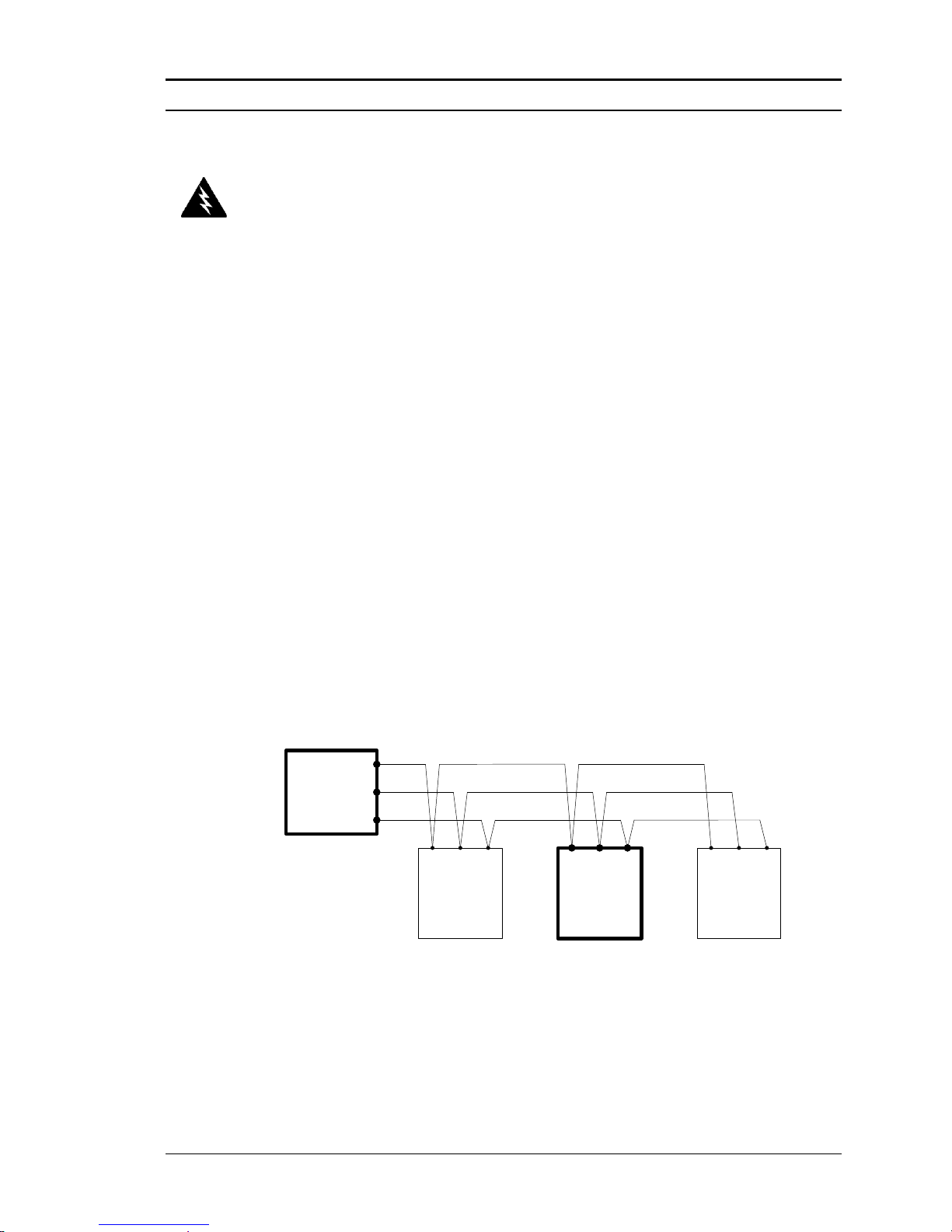
Series M22/M23/M24 Instruction Manual Chapter 4 Serial Communications
M-000-00010 4-9
Modbus Communications
Applicable Flow Meter Models
VorTek Pro-V® Mass Flow Meters, Models M22, M23, and M24 with Modbus
communication protocol and firmware version 4.00.58 and above.
Overview
This document describes the preliminary implementation of the Modbus
communication protocol for use in monitoring common process variables in the
VorTek Pro-V® Vortex flow meter. The physical layer utilizes the half-duplex
RS-485 port, and the Modbus protocol.
Reference Documents
The following documents are available online from www.modbus.org.
Modbus Application Protocol Specification V1.1
Modbus Over Serial Line Specification & Implementation Guide V1.0
Modicon Modbus Protocol Reference Guide PI–MBUS–300 Rev. J
Wiring
An RS485 daisy chained network configuration as depicted below is
recommended. Do not use a star, ring, or cluster arrangement.
RS-485 -
RS-485 +
RS-485 GND
RS-485 Master
Vortex Meter
RS-485 -
RS-485 +
RS-485 GND
RS-485 -
RS-485 +
RS-485 GND
Other Device 2, etc.
RS-485 -
RS-485 +
RS-485 GND
Other Device 1
Figure 4-4.RS-485 Wiring (MODBUS)
Pin Labeling (among devices)
“RS-485 –” = “A” = “TxD-/RxD-” = “Inverting pin”
“RS-485 +” = “B” = “TxD+/RxD+” = “Non-Inverting pin”
“RS-485 GND” = “GND” = “G” = “SC” = “Reference”
Warning!
Place controls in manual
mode when making
configuration changes to
the vortex meter.
Page 88

Chapter 4 Serial Communications Series M22/M23/M24 Instruction Manual
4-10 M-000-00010
Menu Items
The following menu items are in the Output Menu and allow selection and
control of the Modbus communication protocol.
Address
When the Modbus protocol is selected, the Modbus address is equal to the
user programmable device address if it is in the range 1…247, in
accordance with the Modbus specification. If the device address is zero or
is greater than 247, then the Modbus address is internally set to 1.
Comm Protocol
The Comm Protocol menu allows selection of “Modbus RTU Even,” “Modbus
RTU Odd,” or “Modbus RTU None2,” or “Modbus RTU None1,” (non-standard
Modbus) with Even, Odd and None referring to the parity selection. When even
or odd parity is selected, the unit is configured for 8 data bits, 1 parity bit and 1
stop bit; with no parity, the number of stop bits is 1 (non-standard) or 2. When
changing the protocol, the change is made as soon as the Enter key is pressed.
Modbus Units
The Modbus Units menu is to control what units, where applicable, the meter’s
variables will be displayed in. Internal – these are the base units of the meter, °F,
psia, lbm/sec , ft3/sec, Btu/sec , lbm/ft3 Display – variables are displayed in user
selected display unit.
Modbus Order
The byte order within registers and the order in which multiple registers
containing floating point or long integer data are transmitted may be changed
with this menu item. According to the Modbus specification, the most
significant byte of a register is transmitted first, followed by the least significant
byte. The Modbus specification does not prescribe the order in which registers
are transmitted when multiple registers represent values longer than 16 bits.
Using this menu item, the order in which registers representing floating point or
long integer data and/or the byte order within the registers may be reversed for
compatibility with some PLCs and PC software.
Page 89
Series M22/M23/M24 Instruction Manual Chapter 4 Serial Communications
M-000-00010 4-11
The following four selections are available in this menu; when selecting an
item, the protocol is changed immediately without having to press the
Enter key.
0-1:2-3
Most significant register first, most significant byte first (default)
2-3:0-1
Least significant register first, most significant byte first
1-0:3-2
Most significant register first, least significant byte first
3-2:1-0
Least significant register first, least significant byte first
Table 4-1.Byte Order
Note that all of the registers are affected by the byte order, including strings and
registers representing 16-bit integers; the register order only affects the order of
those registers representing 32-bit floating point and long integer data, but does
not affect single 16-bit integers or strings.
Modbus Protocol
The Modbus RTU protocol is supported in this implementation. Supported baud
rates are 1200, 2400, 4800, 9600, 19200, 38400, 57600, and 115200. The default
baud rate is 19200 baud. Depending upon the Modbus protocol selected, data are
transmitted in 8-bit data frames with even or odd parity and 1 stop bit, or no
parity and 2 or 1 (non-standard) stop bits.
The current Modbus protocol specification does not define register usage, but
there is an informal register numbering convention derived from the original
(now obsolete) Modicon Modbus protocol specification, and used by many
vendors of Modbus capable products.
Registers
Usage
Valid Function Codes
00001–09999
Read/write bits ("coils")
01 (read coils) 05 (write single coil)
15 (write multiple coils)
10001–19999
Read-only bits ("discrete inputs")
02 (read discrete inputs)
30001–39999
Read-only 16 bit registers ("input
registers"), IEEE 754 floating point
register pairs, arbitrary length strings
encoded as two ASCII characters per 16bit register
03 (read holding registers) 04 (read
input registers)
40001–49999
Read/write 16-bit registers ("holding
registers"), IEEE 754 floating point
register pairs, arbitrary length strings
encoded as two ASCII characters per 16bit register
03 (read holding registers) 06 (write
single register) 16 (write multiple
registers)
Page 90
Chapter 4 Serial Communications Series M22/M23/M24 Instruction Manual
4-12 M-000-00010
Each range of register numbers maps to a unique range of addresses that are
determined by the function code and the register number. The address is equal to
the least significant four digits of the register number minus one, as shown in the
following table.
Registers
Function Codes
Data Type and Address Range
00001-09999
01, 05, 15
Read/write bits 0000-9998
10001-19999
02
Read-only bits 0000-9999
30001-39999
03, 04
Read-only 16-bit registers 0000-9998
40001-49999
03, 06, 16
Read/write 16-bit registers 0000-9998
Register Definitions
The meter serial number and those variables that are commonly monitored (mass,
volume and energy flow rates, total, pressure, temperature, density, viscosity,
Reynolds number, and diagnostic variables such as frequency, velocity, gain,
amplitude and filter setting) are accessible via the Modbus protocol. Long integer
and floating point numbers are accessed as pairs of 16-bit registers in the register
order selected in the Modbus Order menu. Floating point numbers are formatted
as single precision IEEE 754 floating point values.
The flow rate, temperature, pressure, and density variables may be accessed as
either the flow meter internal base units or in the user-programmed display
units, which is determined by the programming Output Menu’s “Modbus
Units” item. The display units strings may be examined by accessing their
associated registers. Each of these units string registers contain 2 characters of
the string, and the strings may be 2 to 12 characters in length with unused
characters set to zero. Note that the byte order affects the order in which the
strings are transmitted. If the Modbus Order menu (see page 2) is set to 0-1:2-3
or 2-3:0-1, then the characters are transmitted in the correct order; if set to 10:3-2 or 3-2:1-0, then each pair of characters will be transmitted in reverse
order.
Page 91
Series M22/M23/M24 Instruction Manual Chapter 4 Serial Communications
M-000-00010 4-13
Registers
Variable
Data type
Units
Function
code
Addresses
65100-65101
Serial number
unsigned long
—
03, 04
30525-30526
Totalizer
unsigned long
display units*
03, 04
524-525
32037-32042
Totalizer units
string
—
03, 04
2036-2041
30009-30010
Mass flow
float
display units*
03, 04
8-9
30007-30008
Volume flow
float
display units*
03, 04
6-7
30005-30006
Pressure
float
display units*
03, 04
4-5
30001-30002
Temperature
float
display units*
03, 04
0-1
30029-30030
Velocity
float
ft/sec
03, 04
28-29
30015-30016
Density
float
display units*
03, 04
14-15
30013-30014
Viscosity
float
cP
03, 04
12-13
30031-30032
Reynolds number
float
—
03, 04
30-31
30025-30026
Vortex frequency
float
Hz
03, 04
24-25
34532
Gain
char
—
03, 04
4531
30085-30086
Vortex amplitude
float
Vrms
03, 04
84-85
30027-30028
Filter setting
float
Hz
03, 04
26-27
The following registers are available with the energy meter firmware:
Registers
Variable
Data type
Units
Function
code
Addresses
30527-30528
Totalizer #2
unsigned long
display units*
03, 04
526-527
32043-32048
Totalizer #2 units
string
—
03, 04
2042-2047
30003-30004
Temperature #2
float
display units*
03, 04
2-3
30011-30012
Energy flow
float
display units*
03, 04
10-11
The following registers contain the display units strings:
Registers
Variable
Data type
Units
Function code
Addresses
32007-32012
Volume flow units
string
—
03, 04
2006-2011
32001-32006
Mass flow units
string
—
03, 04
2000-2005
32025-32030
Temperature units
string
—
03, 04
2024-2029
32019-32024
Pressure units
string
—
03, 04
2018-2023
32031-32036
Density units
string
—
03, 04
2030-2035
32013-32017
Energy flow units
string
—
03, 04
2012-2017
Table 4-2.Register Definitions
Function codes 03 (read holding registers) and 04 (read input registers) are the
only codes supported for reading these registers, and function codes for writing
holding registers are not implemented. We recommend that the floating point and
long integer registers be read in a single operation with the number of registers
being a multiple of two. If these data are read in two separate operations, each
reading a single 16-bit register, then the value will likely be invalid.
Page 92
Chapter 4 Serial Communications Series M22/M23/M24 Instruction Manual
4-14 M-000-00010
The floating point registers with values in display units are scaled to the same
units as are displayed, but are instantaneous values that are not smoothed. If
display smoothing is enabled (non-zero value entered in the Display TC item
in the Display Menu), then the register values will not agree exactly with the
displayed values.
Exception Status Definitions
The Read Exception Status command (function code 07) returns the exception
status byte, which is defined as follows. This byte may be cleared by setting
“coil” register #00008 (function code 5, address 7, data = 0xff00).
Bit(s)
Definition
0-1
Byte order (see Modbus Order on page 2)
0 = 3-2:1-0 1 = 2-3:0-1
2 = 1-0:3-2 3 = 0-1:2-3
2
Not used
3
Not used
4
Not used
5
Not used
6
Not used
7
Configuration changed
Discrete Input Definitions
The status of the three alarms may be monitored via the Modbus Read Discrete
Input command (function code 02). The value returned indicates the state of the
alarm, and will be 1 only if the alarm is enabled and active. A zero value is
transmitted for alarms that are either disabled or inactive,
Registers
Variable
Function Code
Address
10001
Alarm #1 state
02
0
10002
Alarm #2 state
02
1
10003
Alarm #3 state
02
2
Page 93
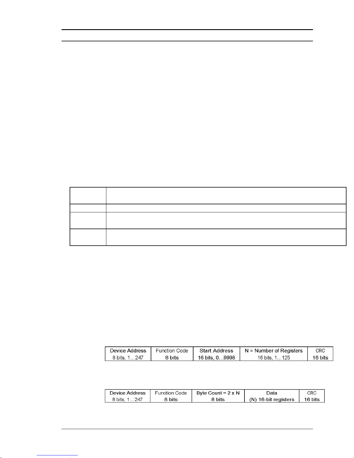
Series M22/M23/M24 Instruction Manual Chapter 4 Serial Communications
M-000-00010 4-15
Control Register Definitions
The only writeable registers in this implementation are the Reset Exception
Status, Reset Meter and Reset Totalizer functions, which are implemented as
”coils” which may be written with the Write Single Coil command (function
code 05) to address 7 through 9, respectively, (register #00008 through #00010).
The value sent with this command must be either 0x0000 or 0xff00, or the meter
will respond with an error message; the totalizer will be reset or exception status
cleared only with a value of 0xff00.
Error Responses
If an error is detected in the message received by the unit, the function code
in the response is the received function code with the most significant bit set,
and the data field will contain the exception code byte, as follows:
If the first byte of a message is not equal to the unit’s Modbus address, if the
unit detects a parity error in any character in the received message (with even or
odd parity enabled), or if the message CRC is incorrect, the unit will not
respond.
Command Message Format
The start address is equal to the desired first register number minus one. The
addresses derived from the start address and the number of registers must all be
mapped to valid defined registers, or an invalid data address exception will occur.
Normal Response Message Format
Exception
Code
Description
01
Invalid function code — function code not supported by device
02
Invalid data address — address defined by the start address and number of registers
is out of range
03
Invalid data value — number of registers = 0 or >125 or incorrect data with the Write
Single Coil command
Page 94
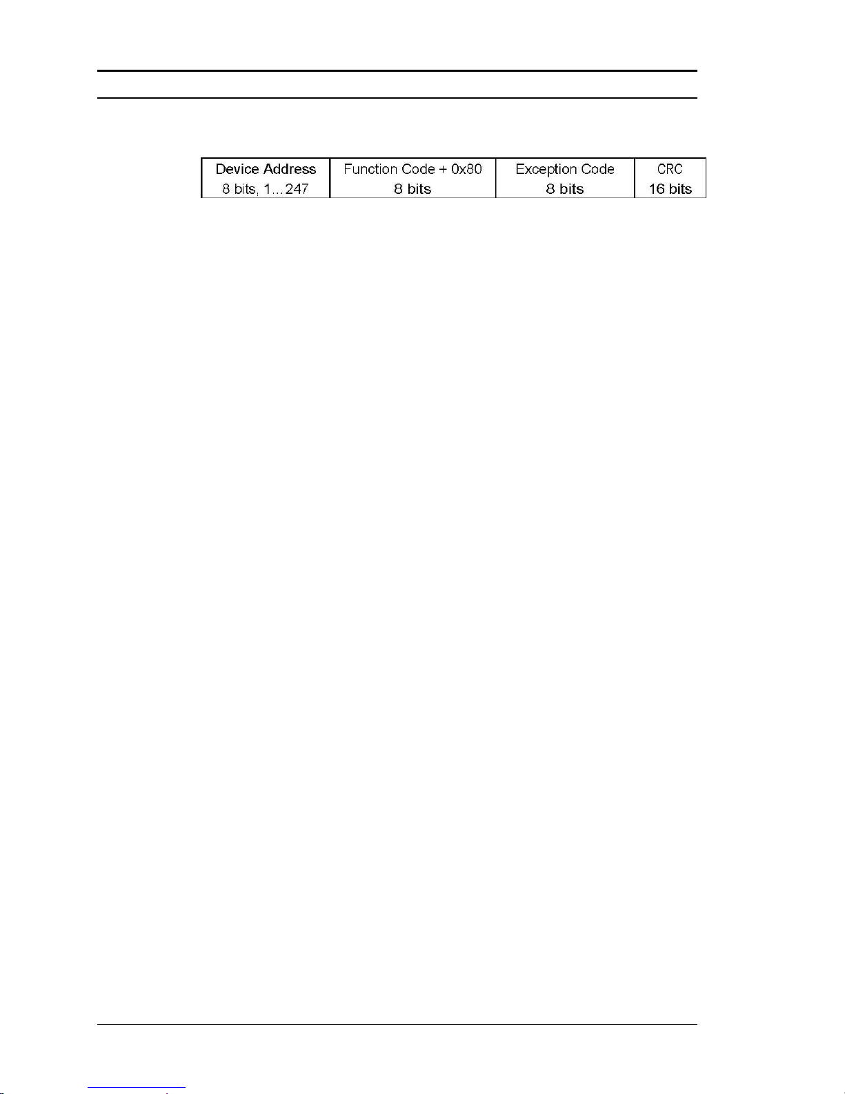
Chapter 4 Serial Communications Series M22/M23/M24 Instruction Manual
4-16 M-000-00010
Exception Response Message Format
Examples
Read the exception status byte from the device with address 1:
01 07 41 E2
01 Device address
07 Function code, 07 = read exception status
41 E2 CRC
A typical response from the device is as follows:
01 07 03 62 31
01 Device address
07 Function code
03 Exception status byte
62 31 CRC
Request the first 12 registers from device with address 1:
01 04 00 00 00 0C F0 0F
01 Device address
04 Function code, 04 = read input register
00 00 Starting address
00 0C Number of registers = 12
F0 0F CRC
A typical response from the device is as follows: *note these are the older
register definitions
01 04 18 00 00 03 E8 00 00 7A 02 6C 62 00 00 41 BA 87 F2 3E BF
FC 6F 42 12 EC 8B 4D D1
01 Device address
04 Function code
18 Number of data bytes = 24
00 00 03 E8 Serial number = 1000 (unsigned long)
00 00 7A 02 Totalizer = 31234 lbm (unsigned long)
6C 62 00 00 Totalizer units = “lb” (string, unused characters
are 0)
41 BA 87 F2 Mass flow rate = 23.3164 lbm/sec (float)
3E BF FC 6F Volume flow rate = 0.3750 ft3/sec (float)
42 12 EC 8B Pressure = 36.731 psia (float)
4D D1 CRC
Page 95

Series M22/M23/M24 Instruction Manual Chapter 4 Serial Communications
M-000-00010 4-17
An attempt to read register(s) that don’t exist
01 04 00 00 00 50 F1 D2
01 Device address
04 Function code 4 = read input register
00 00 Starting address
00 50 Number of registers = 80
F0 36 CRC
results in an error response as follows:
01 84 02 C2 C1
01 Device address
84 Function code with most significant bit set indicates
error response
02 Exception code 2 = invalid data address
C2 C1 CRC
Request the state all three alarms:
01 02 00 00 00 03 38 0B
01 Device address
02 Function code 2 = read discrete inputs
00 00 Starting address
00 03 Number of inputs = 3
38 0B CRC
and the unit responds with:
01 02 01 02 20 49
01 Device address
02 Function code
01 Number of data bytes = 1
02 Alarm #2 on, alarms #1 and #3 off
20 49 CRC
To reset the totalizer:
01 05 00 00 FF 00 8C 3A
01 Device address
05 Function code 5 = write single coil
00 09 Coil address = 9
FF 00 Data to reset totalizer
5C 38 CRC
Page 96

Chapter 4 Serial Communications Series M22/M23/M24 Instruction Manual
4-18 M-000-00010
The unit responds with an identical message to that transmitted, and the totalizer
is reset. If the “coil” is turned off as in the following message, the response is
also identical to the transmitted message, but the totalizer is not affected.
01 05 00 09 00 00 1D C8
01 Device address
05 Function code 5 = write single coil
00 09 Coil address = 9
00 00 Data to “turn off coil” does not reset totalizer
1D C8 CRC
Page 97

Series M22/M23/M24 Instruction Manual Chapter 4 Serial Communications
M-000-00010 4-19
BACnet MS/TP Communications
1. BACnet MS/TP Description
The BACnet Master-Slave/Token-Passing (MSTP) driver
implements a data link protocol that uses the services of the RS485 physical layer. The MS/TP bus is based on BACnet standard
protocol SSPC-135, Clause 9. BACnet MS/TP protocol is a peerto-peer, multiple master protocols based on token passing. Only
master devices can receive the token, and only the device holding
the token is allowed to originate a message on the bus. The token is
passed from master device to master device using a small message.
The token is passed in consecutive order starting with the lowest
address. Slave devices on the bus only communicate on the bus
when responding to a data request from a master device.
2. Baud Rates on the MS/TP Bus
An MS/TP bus can be configured to communicate at one of four
different baud rates. It is very important that all of the devices on
an MS/TP bus communicate at the same baud rate. The baud rate
setting determines the rate at which devices communicate data
over the bus. The baud rate settings available on Pro-V™ Vortex
Mass Flow Meters are 9600, 19200 and 38400.
2.1. Baud Rate and MAC address configuration
1. Power on the IUT
2. Press Enter to go to the configuration menu
3. Enter the factory password 16363 (Use Up and Down arrows to enter
the digits)
4. Navigate with the left arrow to Diagnostics menu
5. Press Enter and press right button immediately
6. Navigate to Config Code screen by continuous pressing down button
7. After reaching config code screen, press right to navigate to Comm.
Type screen
8. Change the comm. Type to “BACnet” and press Enter
Note: BACnet will enable Baud Rate and MAC address screens
9. Press Exit twice to go back to the Diagnostics menu
10. Navigate to Output Menu by using right or left arrow buttons
11. Press Down button and reach Baud Rate and MAC address screens
Page 98
Chapter 4 Serial Communications Series M22/M23/M24 Instruction Manual
4-20 M-000-00010
12. Change the required settings and press Exit & Enter buttons to save
the configuration
13. Reboot the device by power off and on for the changes to take effect
Note:
a. IUT support 9600, 19200, 38400 baud rates
b. MAC address range is 0-127
3. Supported BACnet Objects
A BACnet object represents physical or virtual equipment
information, as a digital input or parameters. The Pro-V™ Vortex
Mass Flow Meters presents the following object types:
a. Device Object
b. Analog Input
c. Binary Input
d. Binary Value
Each object type defines a data structure composed by properties
that allow the access to the object information. The below table
shows the implemented properties for each Vortex Mass Flow
Meters object type.
Properties
Object Types
Device
Analog Input
Binary Input
Binary
Value
Object_Identifier
Object_Name
Object_Type
System_Status
Vendor_Name
Vendor_Identifier
Model_Name
Firmware_Revision
Application-Software-Version
Protocol_Version
Protocol_Revision
Protocol_Services_Supported
Protocol_Object_Types_Supported
Page 99
Series M22/M23/M24 Instruction Manual Chapter 4 Serial Communications
M-000-00010 4-21
(W) – Writable Property.
3.1. Device Object:
The Device object default property values are as follows –
Property Name
Default Values
object-identifier
7
object-name
Device,1
object-type
Device
system-status
operational
vendor-name
VorTek Instruments
vendor-identifier
558
model-name
Multivariable Flowmete
firmware-revision
N/A
application-softwareversion
1.07
protocol-version
1
protocol-revision
4
protocol-servicessupported
{F,F,F,F,F,F,F,F,F,F,F,F,T,F,T,T,T,T,F,F,F,F,F,F,F,F,F,F,F,F,T,T,F,F,F,F,F}
protocol-object-types-
{T,F,F,T,F,T,F,F,T,F,F,F,F,F,F,F,F,F,F,F,F,F,F,F,F}
Object_List
Max_ADPU_Length_Accepted
Segmentation_Supported
ADPU_Timeout
Number_Of_ADPU_Retries
Max_Masters
Max_Info_Frames
Device_Address_Binding
Database_Revision
Status_Flags
Event_State
Reliability
Out_Of_Service
(W)
(W)
(W)
Units
Polarity
(W)
Priority_Array
Relinquish_Default
Status_Flag
Present_Value
(W)
(W)
(W)
Inactive_Text
Active_Text
Page 100
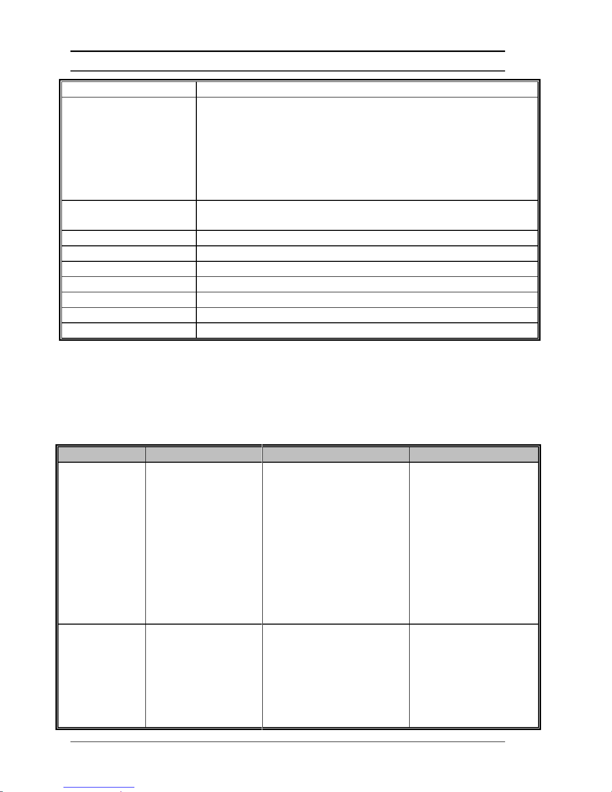
Chapter 4 Serial Communications Series M22/M23/M24 Instruction Manual
4-22 M-000-00010
supported
object-list
{(analog-input,1),(analog-input,2),(analog-input,3),(analog-input,4),
(analog-input,5), (analog-input,6),(analog-input,7),(analog-input,8)
(analog-input,9),(analog-input,10), (analog-input,11), (analoginput,12), (analog-input,13),(analog-input,14), (analoginput,15),(analog-input,16),(analog-input,17), (analoginput,18),(analog-input,19),(binary-input,1),(binary-input,2),(binaryinput,3),(binary-input,4), (binary-value,1), (device,7) }
max-apdu-lengthaccepted
300
segmentation-supported
no-segmentation
apdu-timeout
3000
number-of-APDU-retries
1
max-master
127
max-info-frames
1
device-address-binding
()
database-revision
0
Note - Device Communication Control: Password – “vortek”
3.2. Analog Input Object:
Vortex Mass Flow Meters Analog Input type objects are described
in the below Table –
Object Instance
Object Name
Unit
Description
1
Volume Flow
cubic-feet-per-second,
cubic-feet-per-minute,
us-gallons-per-minute,
imperial-gallons-perminute,
liters-per-minute,
liters-per-second,
liters-per-hour,
cubic-meters-per-second,
cubic-meters-per-minute,
cubic-meters-per-hour
This AI object is used to
measure volume flow.
2
Mass Flow
pounds-mass-per-second,
grams-per-second,
kilograms-per-second ,
kilograms-per-minute ,
kilograms-per-hour,
pounds-mass-per-minute ,
pounds-mass-per-hour,
This AI object is used to
measure mass flow.
 Loading...