

Page 1
UNIVERSAL
CARBURETOR ENCLOSURE
1650 PACIFIC AVENUE • CHANNEL ISLANDS, CA 93033-9901
P/N: 007051
©2000 Vortech Engineering, Inc.
All Rights Reserved, Intl. Copr. Secured
11SEP00 V 1.0
(Carb-Enclosure 007051)
®
ENGINEERING, INC.
Page 2

FOREWORD
Proper installation of this supercharger kit requires general automotive mechanic
knowledge and experience. Please browse through each step of this instruction manual
prior
to beginning the installation to determine if you should refer the job to a professional
installer/technician. Please call Vortech Engineering for installers in your area.
All rights reserved. No parts of this publication may be reproduced, transmitted, transcribed,
or translated into another language in any form, by any means without written permission
P/N: 007051
©2000 Vortech Engineering, Inc.
All Rights Reserved, Intl. Copr. Secured
11SEP00 V 1.0
(Carb-Enclosure 007051)
© 2000 VORTECH ENGINEERING, INC.
of Vortech Engineering, Inc.
i
Page 3
UNIVERSAL CARBURETOR ENCLOSURE
Table Of Contents
FOREWORD ...................................................................................................................... i
TABLE OF CONTENTS ..................................................................................................... ii
PARTS LIST ....................................................................................................................... iii
CARBURETOR ENCLOSURE INSTALLATION................................................................. 1
©2000 Vortech Engineering, Inc.
ii
All Rights Reserved, Intl. Copr. Secured
11SEP00 V 1.0
P/N: 007051
(Carb-Enclosure 007051)
Page 4

UNIVERSAL CARBURETOR ENCLOSURE
Part No. 8M205-012/8M205-018/8M205-020
®
ENGINEERING, INC.
IMPORTANT: Before beginning installation, verify that all parts are included in
the kit. Report any shortages or damaged parts immediately.
Item Description Vortech Part # Qty. Item Description Vortech Part # Qty.
CARBURETOR ENCLOSURE ASSY, WITH LINES
(4150 HOLLEY LINES) .................................
ENCL. STD. MACH. ASSY. ........................ 8M105-012......................1
MANIFOLD, UPPER COOLER .................. 8M003-011......................1
5/16-18 X 2 1/8 SS SHCS ........................... 7A312-212 ......................2
5/16-18 X 3/4 SS SHCS .............................. 7A312-078 ......................14
1/4 NPT PLUG ............................................ 7P250-120 ...................... 1
FITTING, -3 TO 1/4 HOSE .......................... 7P187-102 ......................1
O-RING, -3 .................................................. 7U100-003 ......................4
PLUG, -3 BUTTONHEAD w/O-RING ......... 7P187-103 ...................... 3
PLUG, OIL HOLE ....................................... 7P375-104 ......................4
3/8" COPPER WASHER............................. 7J375-024 ....................... 4
5/16 STUD .................................................. 7A312-252 ......................4
5/16-24 JAM NUT ....................................... 7F312-024.......................4
5/16 FLAT WASHER-SAE .......................... 7J312-000 ....................... 4
O-RING ....................................................... 7U100-008 ...................... 1
PLUG, AN -8 O-RING PORT ...................... 7P500-087 ......................1
THROT LINK ASSY, CARB ENCL ............. 8M110-010 ...................... 1
BRACKET, IDLE ...................................... 8M010-010 ...................... 1
THROTTLE ARM OUTER ....................... 8M010-030......................1
THROTTLE ARM INNER ......................... 8M010-040......................1
THROTTLE SHAFT ................................. 8M010-050......................1
RETAINER, SPRING ENCL. ................... 8M010-070 ...................... 1
RETAINER, SPRING THROTTLE........... 8M010-080 ......................1
SPRING, THROTTLE ENCL. .................. 8M010-090......................1
-012 WITHOUT FUEL LINES, SATIN/-018 WITHOUT FUEL LINES, POLISHED/-020 WITH OPTIONAL HOLLEY FUEL LINE KIT,
SATIN
PARTS LIST
8M205-020 1
SHAFT, 5/16 HEX .................................... 8M010-140 ...................... 1
SPACER, ENCL. ..................................... 2A017-032 ...................... 1
NUT , THROTTLE.....................................7F010-026.......................1
WASHER, THROTTLE ............................ 7J010-687 ....................... 1
3/16 ROD END RH WITH NUT ............... 7C010-187 ...................... 1
3/16 ROD END LH WITH NUT ................ 7C010-188 ...................... 1
10-24 X 3/4 SS BHCS ............................. 7C010-077 ...................... 4
10-24 X 1/2 SS BHCS ............................. 7C010-052 ...................... 4
SPACER, SHAFT ENCL. ......................... 2A017-031 ...................... 1
10-32 SCREW ......................................... 7C011-075 ......................1
10-32 NUT ............................................... 7F010-033.......................1
#10 FLAT WASHER ................................ 7J010-001 ....................... 4
1/4-20X3/4 SHCS SS .............................. 7A250-076 ...................... 1
FUEL LINE ASSY, (OPT.) HOLLEY 4150... 8M110-020 ......................1
FRONT FUEL LINE ................................. 8M010-100 ...................... 1
REAR FUEL LINE.................................... 8M010-110 ...................... 1
MALE TEE -8,-6,-6 .................................. 7P500-084 ......................1
FITTING, -8 BULKHEAD w/O-RING ....... 7P500-085 ......................1
FITTING, -8 BULKHEAD NUT, BLK ........ 7P500-089 ......................1
PLUG BTNHD, AN -8 w/O-RING, BLK .... 7P500-087 ......................2
FTG, AN -8 MALE w/O-RING, BLK ......... 7P500-088 ...................... 1
AN -8 HOSE END, STRAIGHT ............... 7P500-083 ......................1
120° -8 TO 1/2" BARB ............................. 7P500-086 ......................1
1/2" FUEL LINE ....................................... 7U037-030 ...................... 5.4”
1/8 NPT PLUG......................................... 7P125-016 ......................1
O-RING, -8 .............................................. 7U100-008 ...................... 3
OPTIONAL PARTS PART # USED FOR:
HOLLEY CARB GASKET ............. 8M001-017.... USE BETWEEN INT AKE MANIFOLD AND ENCLOSURE OR BETWEEN ENCLOSURE AND CARBURETOR
TBODY GASKET FORD .............. 8M001-018.... USE ON ENCLOSURE INLET FLANGE
FTG, 1/4 NPT-1/2 BARB 90°.........7P250-084 .... USE ON BACK OF ENCLOSURE FOR PCV
FTG, 1/4 NPT - 3/8 BARB 90° ....... 7P250-047 .... USE ON ENCLOSURE FOR PCV
RETAINER, MORSE .................... 8M010-020.... HOLDS MORSE CABLE ON BACK OF ENCLOSURE FOR DIRECT THROTTLE HOOKUP
O-RING, MORSE CABLE SEAL ... 7U100-010 .... INSTALLS ON MORSE CABLE BEFORE INSERTING THROUGH CARB ENCLOSURE
MACHINE, Ø3.5 FLANGE ............8M003-041 .... ALLOWS INSTALLA TION OF 3 1/2" SLEEVE ON ENCL. CVR, EXIT PERPENDICULAR T O VALVE CVR
MACHINE, Ø3.5 FLANGE 90° ...... 8M012-011 .... ALLOWS INSTALLATION OF 3 1/2" SLEEVE ON ENCLOSURE CVR, EXIT PARALLEL T O VALVE CVR
AN -6 - HOLLEY ADPTR .............. 7P375-107 .... THREADS INTO HOLLEY CENTER HUNG FLOAT BOWLS, DASH 6 MALE OUTLET
P/N: 007051
©2000 Vortech Engineering, Inc.
All Rights Reserved, Intl. Copr. Secured
11SEP00 V 1.0
(Carb-Enclosure 007051)
Fig. 1
iii
Page 5

CARBURETOR ENCLOSURE INSTALLATION
A. Relieve the fuel pressure in the system.
B. Remove the carburetor from the intake manifold.
C. Thoroughly clean the intake manifold carburetor
flange.
D. Thread the four supplied carburetor flange studs
into the intake manifold.
E. Install a new carburetor gasket.
F. Install the lower part of the carburetor enclosure
over the studs until it sits flat on the intake
manifold.
G. Install a new carburetor gasket over the studs
until it sits flat on the carburetor enclosure carburetor mounting surface.
H. With the carburetor in a suitable work area, bend
the damper tab on the main throttle arm until it is
flat. (See
I. Install the throttle nut through the large hole on
the outside of the throttle arm. Using a 10-24 cap
screw inserted through a rod end and the #10
fender washer, thread into the throttle nut and
tighten. (See
Figs. 2, 3, 4
Figs. 5, 6
.)
.)
Fig. 2
Fig. 6
Fig. 3
Fig. 4
Fig. 5
©2000 Vortech Engineering, Inc.
1
All Rights Reserved, Intl. Copr. Secured
11SEP00 V 1.0
P/N: 007051
(Carb-Enclosure 007051)
Page 6

CARBURETOR ENCLOSURE INSTALLATION, cont’d.
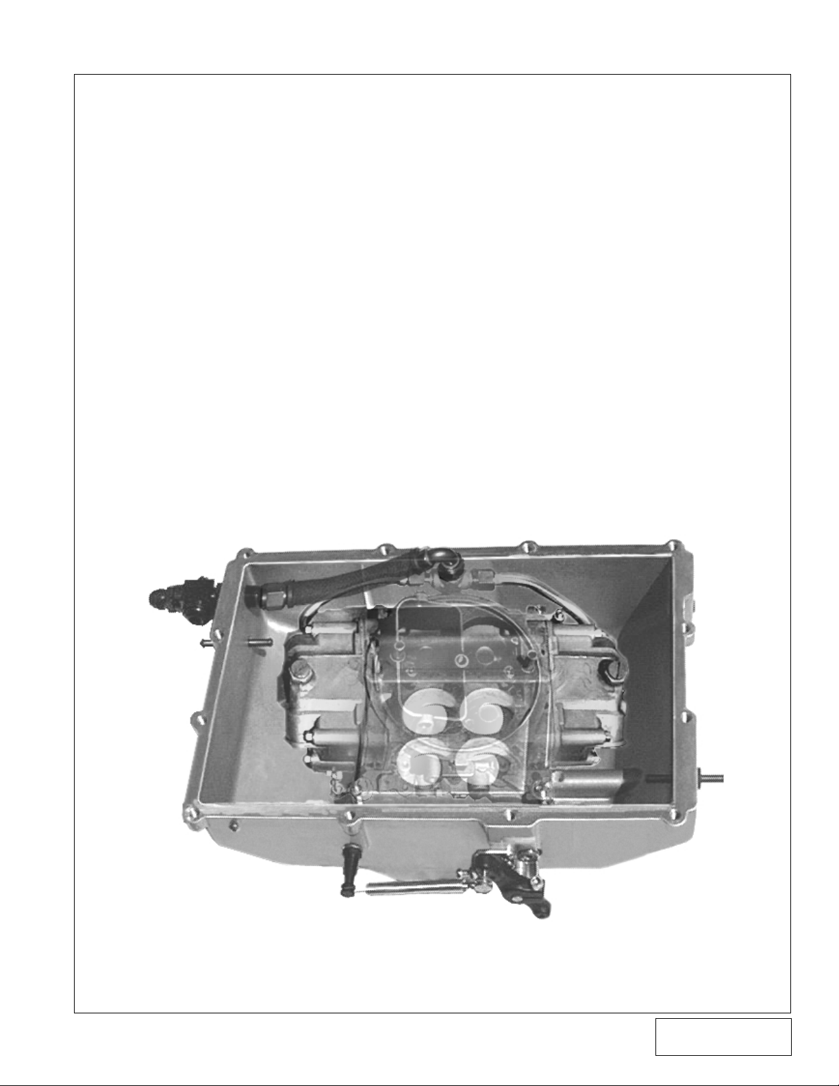
J. Install the carburetor in the enclosure until it sits
flat on the flange.
K. Install two of the brass plugs in each side of the
carburetor enclosure. Make sure the copper crush
washers are installed between the brass plugs
and the enclosure. (See
Fig. 8
.)
L. Install the idle bracket on the outside of the
enclosure using two 1/2” screws. (See
Fig. 9
.)
M. With the one armed throttle arm on the inside of
the enclosure, insert the splined shaft through
the throttle bushing on the side of the carburetor
enclosure.
N. Install the large brass spacer over the splined
shaft until it rests flat against the outside of the
enclosure. (See
Fig. 9
.)
O. Line up the two armed throttle arm with the inner
throttle arm and slide onto the splined shaft.
P. Tighten the clamp screws on both of the throttle
arms. Rotate the throttle linkage to verify free
movement. If drag is felt, adjust the distance
between the two throttle arms.
Q. Install the remaining rod end on the outer hole on
the inside of the inside throttle arm and tighten
screw.
R. Install the carburetor over the carburetor studs
until it sits flat on the gasket.
S. Install the four 5/16” nuts and washers on the
studs and tighten.
T. With a jam nut installed on each rod end, install
the 5/16” coupler shaft between the two rod ends.
Adjust the coupler until the angle of the carburetor enclosure throttle arm matches that of the
carburetor throttle arm.
U. Install the supplied 10-32 jam nut on the 1” 10-32
screw and insert into the idle bracket. (See
Fig. 9
V. Install the fuel lines on the carburetor. See Fig. 10
if optional Vortech fuel lines are used, and proceed with the following steps:
1. Install the -8 bulkhead nut and O-ring on the
bulkhead fitting.
2. Thread the bulkhead fitting into the front
hole in the carburetor enclosure.
3. Install the fuel lines into the carburetor bowls
loosely.
4. Connect the free end of each fuel line to the
-8/-6/-6 TEE.
5. Install the -8 straight hosebarb fitting on the
inside of the bulkhead fitting. Install the -8
120° fitting on top of the TEE.
6. Measure and cut the supplied pushlock
hose so that it will fit well between the two
installed barb fitttings.
NOTE: The 10-24 screw should not
protrude past the nut. Use
washers as necessary to adjust the thread depth.
Fig. 7
Brass Plugs w/Copper Washers
Fig. 8
.)
Fig. 9
P/N: 007051
©2000 Vortech Engineering, Inc.
All Rights Reserved, Intl. Copr. Secured
11SEP00 V 1.0
(Carb-Enclosure 007051)
2
Page 7

Carburetor Enclosure Installation, cont’d.
7. Remove the barbed fittings, coat the barbs
with grease, and fully insert the barbed
fittings in the hose.
8. Install the fuel hose assembly and tighten
all of the fuel line connections.
W. Hose connections to the carburetor enclosure will
vary widely depending on the application. All
hoses that are not used should be plugged with
the supplied -3, -8, 1/8 NPT and 1/4 NPT plugs.
X. Using the supplied 5/16” cap screws, install the
top cover on the enclosure and tighten the screws.
The cover opening must be pointed away from
the throttle linkage for the idle bracket to be
utilized. If the cover opening must point to the
side where the throttle linkage is located, remove
the idle bracket and brass spacer. Install a 5/16”
washer and re-install the outer throttle arm.
NOTE: All -3 and -8 fittings should
have an O-ring installed before using.
Fig. 10
Fig. 11
3
©2000 Vortech Engineering, Inc.
All Rights Reserved, Intl. Copr. Secured
11SEP00 V 1.0
P/N: 007051
(Carb-Enclosure 007051)
Page 8

®
ENGINEERING, INC.
1650 PACIFIC AVENUE • CHANNEL ISLANDS, CA 93033-9901 • (805) 247-0226
FAX (805) 247-0669 • www.vortechsuperchargers.com • M-F 8:00 AM - 4:30 PM PST
©2000 Vortech Engineering, Inc.
All Rights Reserved, Intl. Copr. Secured
11SEP00 V 1.0
P/N: 007051
(Carb-Enclosure 007051)
 Loading...