

Page 1
®
BIG BLOCK CHEVROLET
CARBURETED SYSTEM
(TWIN PLATE)
Installation Instructions*
*Legal in California only for off-road vehicles which may never be used upon a highway.
ENGINEERING, LLC
1650 PACIFIC AVENUE • CHANNEL ISLANDS, CA 93033-9901 • (805) 247-0226
FAX (805) 247-0669 • www.vortechsuperchargers.com • M-F 8:00 AM - 4:30 PM PST
P/N: 4GA020-030
©2008 Vortech Engineering, LLC
All Rights Reserved, Intl. Copr. Secured
08DEC08 V3.0(BBC LowMount(4GA..030 V3.0))
Page 2

FOREWORD
STOP
his manual provides information on the installation, maintenance and service of the
Vortech supercharger kit expressly designed for this vehicle. All information, illustra-
T
tions and specifications contained herein are based on the latest product information
available at the time of this publication. Changes to the manual may be made at any time
without notice. Contact Vortech Engineering for any additional information regarding this kit
and any of these modifications at (805) 247-0226 8:00am-4:30pm PST M-F..
Take note of the following before proceeding:
1. Proper installation of this supercharger kit requires general
automo tive mechanic knowledge and experience. Please browse
through each step of this instruction manual prior to beginning the
installation to determine if you should refer the job to a professional
installer/technician. Please contact your dealer or Vortech Engineering
for possible installers in your area.
2. This product was designed for use on stock (un-modified, OEM) vehicles. The
PCM (computer), engine, transmission, drive axle ratios and tire O.D. must be stock. If
the vehicle or engine has been modified in any way, check with Vortech prior to installation and use of this product.
3. Use only premium grade fuel with a minimum of 91 octane (R+M/2).
4. Always listen for any sign of detonation (knocking/pinging) and discontinue hard use (no
boost) until the problem is resolved.
5. Vortech is not responsible for any clutch, transmission, drive-line or engine damage.
Exclusions from Vortech warranty coverage considerations include, but
not limited to:
1. Neglect, abuse, lack of maintenance, abnormal operation or improper installation.
2. Continued operation with an impaired vehicle or sub-system.
3. The combined use of Vortech components with other modifications such as, but not limit-
ed to, exhaust headers, aftermarket camshafts, nitrous oxide, third party PCM programming or other such changes.
© 2008 VORTECH ENGINEERING, LLC
All rights reserved. No part of this publication may be reproduced, transmitted, transcribed,
or translated into another language in any form, by any means without written permission
of Vortech Engineering, LLC.
P/N: 4GA020-030
©2008 Vortech Engineering, LLC
All Rights Reserved, Intl. Copr. Secured
08DEC08 V3.0(BBC LowMount(4GA..030 V3.0))
ii
Page 3

Important Installation Notes:
A. This system was designed to fit on engines equipped with a “long” water
pump. Vortech includes a 3-groove assessory drive crank pulley (for use with
a “short” water pump, a custom accessory drive crank pulley and spacer will
be required).
B. For engines equipped with power steering, a remote reservoir (GM “type 2”)
style pump will be required as well as an optional Vortech power steering
pump bracket and pulley assembly. Depending on the vehicle, power steering
lines may require fabrication.
— Power Steering Pump: OE on 1987 GM Pontiac Sunbird, NAPA #20-874
— Vortech Power Steering bracket/pulley assembly: 4GA110-010
The following carbureted system support parts are not included as
part of the system but are available from Vortech:
1. Optional fuel line/fitting kits for the carburetor. They include custom bent
stainless steel lines, billet-8 bulkhead adapter with fuel pressure port and
plug, -8/-6 junction TEE, aluminum swivel hose ends and USCG
approved fuel hose.
• Vortech #8M110-020 4150 series (w/dual metering blocks), SS fuel line
kit
• Vortech #8M110-030 Demon series, SS fuel line kit
2. Carburetor air diffuser. Straightens airflow into the carburetor for
improved response/driveability
• Vortech #8M011-001 Ø5.75" x 2.50 tall carburetor air diffuser, stainless
steel
3. Compressor bypass valve and flange (required on applications exceed-
ing 5 psig boost) (Contact the technical department to determine the
proper valve selection for the application)
• Vortech #8D204-001 Race Bypass Valve
• Vortech #8D004-052 Race Bypass weld-on flange (aluminum)
• Vortech #8D103-001 Mondo Race Bypass Valve
• Vortech #8D003-052 Mondo Race Bypass weld-on flange (aluminum)
• Vortech #8D205-003 BV57 Bypass Valve weld-on flange
• Vortech #8D005-051 BV57 Bypass Valve weld-on flange (aluminum)
4. Supercharger air inlet ducting (see step 8. in this manual)
5. Vortech power steering bracket/pulley assembly (see notes above):
#4GA110-010
Items to be supplied by installer/end user:
• Carburetor with mechanical secondaries (4150 Holley/Barry Grant MD
style)
• High performance fuel pump (boost referenced)
iii
08DEC08 V3.0(BBC LowMount(4GA..030 V3.0))
©2008 Vortech Engineering, LLC
All Rights Reserved, Intl. Copr. Secured
P/N: 4GA020-030
Page 4

TABLE OF CONTENTS
FOREWORD ........................................................ ii
TABLE OF CONTENTS ...............................................iv
COPYRIGHT NOTICE . . . . . . . . . . . . . . . . . . . . . . . . . . . . . . . . . . . . . . . . . . . . . . . . v
PARTS LIST (Big Block Chevrolet Carbureted System) ......................vi
PARTS LIST (Base Kit, Universal BBC V4 Carb) ...........................viI
TOOL AND SUPPLY REQUIREMENTS . . . . . . . . . . . . . . . . . . . . . . . . . . . . . . . . . .viiI
1. PREPARATION/REMOVAL . . . . . . . . . . . . . . . . . . . . . . . . . . . . . . . . . . . . . . . . . 1
2. CRANK PULLEY . . . . . . . . . . . . . . . . . . . . . . . . . . . . . . . . . . . . . . . . . . . . . . . . . 2
3. SUPERCHARGER OIL FEED . . . . . . . . . . . . . . . . . . . . . . . . . . . . . . . . . . . . . . . 3
4. SUPERCHARGER OIL DRAIN . . . . . . . . . . . . . . . . . . . . . . . . . . . . . . . . . . . . . . 4
5. SUPERCHARGER MOUNTING . . . . . . . . . . . . . . . . . . . . . . . . . . . . . . . . . . . . . 5
6. ACCESSORY DRIVE BELTS ........................................7
7. SUPERCHARGER DRIVE BELT INSTALLATION ........................ 8
8. SUPERCHARGER MOUNTING RACE (V-4 ONLY) . . . . . . . . . . . . . . . . . . . . . . 10
9. ACCESSORY DRIVE BELTS - V-4 ONLY ..............................11
10. SUPERCHARGER DRIVE BELTS - V-4 ONLY ..........................12
11. AIR INLET SUGGESTIONS .........................................13
12. DISCHARGE DUCTING/CARBURETOR ENCLOSURE ...................14
13. FINAL REASSEMBLY AND CHECK . . . . . . . . . . . . . . . . . . . . . . . . . . . . . . . . . .15
P/N: 4GA020-030
©2008 Vortech Engineering, LLC
All Rights Reserved, Intl. Copr. Secured
08DEC08 V3.0(BBC LowMount(4GA..030 V3.0))
iv
Page 5

NOTICE
This product is protected by state common law, copyright and/or patent. All
legal rights therein are reserved. The design, layout, dimensions, geometry, and engineering features shown in this product are the exclusive property of Vortech Engineering, LLC. This product may not be copied or duplicated in whole or part, abstractly or fundamentally, intentionally or fortuitously, nor shall any design, dimension, or other information be incorporated into any product or apparatus without prior written consent of Vortech
Engineering, LLC.
v
08DEC08 V3.0(BBC LowMount(4GA..030 V3.0))
©2008 Vortech Engineering, LLC
All Rights Reserved, Intl. Copr. Secured
P/N: 4GA020-030
Page 6
Big Block Chevrolet Carbureted System
®
Part No. 4GA218-030
ENGINEERING, LLC
PARTS LIST
IMPORTANT: Before beginning installation, verify that all parts are included in the kit. Report any shortages or damaged parts imme-
diately.
PART NO. DESCRIPTION QTY. PART NUMBER DESCRIPTION QTY.
2A258-040 SUPERCHARGER ASY 1
4GA111-031 BRKT ASSY, S/C MNT BBC DUAL LO 1
4GA010-051 MTG PLT, BBC LOW MNT DUAL 1
4GA010-061 SPRT PLT, S/C BBC DUAL LOW 1
2A017-049 SPACER A, SBCHEV CARB BRKT 6
4GA010-044 S/C MTG PLT, BBC LOW MOUNT 1
4GA011-021 MACH MTG BRKT, BBC LOW MOUNT 1
7C012-022 M12 X 1.75 X 20MM THIN HD 3
7J012-092 12MM WASHER, FLAT 3
7A375-126 3/8-16 X 1.25 HHCS, GR8, PLT 6
7A375-275 3/8-16 X 2-3/4 HXCSG8P ZINC 4
7A375-300 3/8-16 X 3" HXCSG5P 1
7K375-040 3/8 AN960 FLAT WASHR PLATED 17
7A437-200 7/16-14 X 2" SHCS 2
7A437-425 7/16"-14X4.25" HX HD 1
7J438-081 7/16 SAE WASHER PLATED 1
7F375-017 3/8-16 NYLOCK NUT 2
7A375-201 3/8-16 X 2" S.S. SHCS 2
7A375-426 3/8-16 X 4.25" HX HD GR8 1
7B375-276 3/8-24 X 2.75" HX HD GR8 2
4GA118-011 DRIVE ASY, BBC DUAL 10-RIB 7" 1
4MA018-051 CRANK PLY, 7", UNIVERSAL 1
4MA017-061 SPACER, CRK PLY, GEN2 V-GRV 1
4GA018-011 CRK PLY, ACC, BBC LNG H20 PMP 1
7A375-475 3/8-16 X 4.75" HX HD GR8 PLTD 3
7J375-044 3/8 FLAT WASHR PLATED 3
2A041-618 BELT, 10 RIB X 61.75 EFFECT LENGTH 1
4GA130-036 OIL DRAIN ASSY, BBC LOW MT 1
7U030-036 1/2" OIL DRAIN HOSE 2.5'
7R001-008 #8 STNLS HOSE CLAMP 2
7P375-017 3/8NPT X 1/2 BEADED HSE BRB 1
4MA130-026 OIL FEED ASSY BBC 1
4MA145-020 OIL FEED HOSE ASSY, BBCKIT 1
7P125-026 1/8 NPT X #4 SAE FLARE, 90° 2
7P125-034 1/8NPTX1/8NPT STRT T 1
7P125-103 1/8NPT X 45° -4SAE FLARE 2
7P250-036 -4 SAE FLARE TO 1/4 NPT 1
7P250-120 1/4 NPT PIPE PLUG 1
8M205-012 CARB ENCL ASSY, UNIV SAT, G2 L 1
4GA111-041 TENS. ASSY. BBC DUAL LOW 10-RI 1
7B500-325 ARBOR, S/C TENS PLY, S2000 1
7PA375-500 SCREW, IDLER ADJUST, 5.00" 1
4PFA010-031 BRACKT, IDLER ADJUST SCREW 1
4FP116-030 IDLER W/BRNG ASSY, 36MM COG 1
4GA017-011 SPCR, IDLR,DL. PLT BBC 10-RIB 1
2A017-750-490 SPCR, ARBR,10-RB,DL.PLT BBC 1
7B500-240 ARBOR, S/C TENS PLY, RENEGADE 1
7F500-020 1/2"-20 HEX JAM NUT GR5 ZINC 1
4FD017-011 PILOT, 6203/5 BRG, 1/2 SCREW 1
7A250-100 1/4-20 X 1 FLAT ALLEN 2
4GA112-020 DISCH ASSY, BBC LOW MOUNT 1
4GA012-021 DISCH TUBE, BBC LOW MOUNT 1
7A312-100 5/16-18 X 1 HHCS, GR5, PLATED 4
7K312-001 5/16 AN WASHER, PLATED 4
7R002-048 #48 SAE TYPE F SS HOSE CLAMP 1
7R002-056 #56 SAE TYPE F SS HOSE CLAMP 3
7S350-200 SLEEVE, 3-1/2 X 2, BLUE 1
7S350-301 REDUCER, 3.50-3.00 1
8M012-011 MACH, 90° CARB BOX INLET 1
008110 SMALL SILVER DIE CUT DECAL 2
008444 3 YR S/C STRT INFO PKG ASY VOR 1
008130 LICENSE PLATE FRAME, VORTECH 1
4GA020-030 INSTR MAN, BBC LOW MOUNT KIT 1
P/N: 4GA020-030
©2008 Vortech Engineering, LLC
All Rights Reserved, Intl. Copr. Secured
08DEC08 V3.0(BBC LowMount(4GA..030 V3.0))
vi
Page 7
Base Kit, Universal BBC V4 Carb
®
Part No. 3GA218-060
ENGINEERING, LLC
PARTS LIST
IMPORTANT: Before beginning installation, verify that all parts are included in the kit. Report any shortages or damaged parts imme-
diately.
PART NO. DESCRIPTION QTY. PART NUMBER DESCRIPTION QTY.
008110 SMALL SILVER DIE CUT DECAL 2
008130 LICENSE PLATE FRAME, VORTECH 1
008443 S/C RACE INFO PKG ASSY VORT 1
4GA020-030 INSTR MAN, BBC LOW MOUNT KIT 1
4GA111-051 TENS. ASSY. COG, BBC DL PLT.LO 1
7G012-175 MACH NUT, COG DRV, SPECIAL 1
4FP017-021 SPACR, IDLR, DUAL PLT 50MM DRV 1
4FP116-020 IDLER W/BRNG ASSY, 50mm 1
4FD017-011 PILOT, 6203/5 BRG, 1/2 SCREW 1
7C012-065 M12 X 1.75 X 65MM HX 1
4GA111-061 BRKT ASSY, S/C MNT V4 BBC 1
4GA010-071 BRACKET,S/C BBC DUAL PLT RACE 1
4GA010-081 BRACKET,SPRT BBC DL. PLT RACE 1
2A017-049 SPACER A, SBCHEV CARB BRKT 8
4GA011-021 MACH MTG BRKT, BBC LOW MOUNT 1
7C012-022 M12 X 1.75 X 20MM THIN HD 3
7A375-126 3/8-16 X 1.25 HHCS, GR8, PLT 9
7A375-275 3/8-16 X 2-3/4 HXCSG8P ZINC 5
7A375-300 3/8-16 X 3" HXCSG5P 3
7K375-040 3/8 AN960 FLAT WASHR PLATED 19
7F375-017 3/8-16 NYLOCK NUT 2
7A437-200 7/16-14 X 2" SHCS 2
7A437-425 7/16"-14X4.25" HX HD 1
7J438-081 7/16 SAE WASHER PLATED 1
7A375-201 3/8-16 X 2" S.S. SHCS 2
7A375-426 3/8-16 X 4.25" HX HD GR8 1
4GA118-031 DRIVE ASY, BBC DUAL LOW COG 1
2A032-032 S/C PULLEY, 32T (50MM) 1
8R101-007 PULLEY RETAINER ASSY 50 MM COG 1
4MA018-080 CRANK PLY, 80T GT 8MM X 2.5W 1
4MA017-061 SPACER, CRK PLY, GEN2 V-GRV 1
4GA018-011 CRK PLY, ACC, BBC LNG H20 PMP 1
2A042-160 BELT, PC GT2 COG 1600X8MX36 1
7A375-475 3/8-16 X 4.75" HXHD GR8 PLTD 3
7K375-040 3/8 AN960 FLAT WASHR PLATED 3
4GA130-036 OIL DRAIN ASSY, BBC LOW MT 1
7U030-036 1/2" OIL DRAIN HOSE 2.5'
7R001-008 #8 STNLS HOSE CLAMP 2
7P375-017 3/8NPT X 1/2 BEADED HSE BRB 1
4MA130-026 OIL FEED ASSY BBC 1
4MA145-020 OIL FEED HOSE ASSY, BBCKIT 1
7P125-026 1/8 NPT X #4 SAE FLARE, 90° 2
7P125-034 1/8NPTX1/8NPT STRT T 1
7P125-103 1/8NPT X 45° -4SAE FLARE 2
7P250-036 -4 SAE FLARE TO 1/4 NPT 1
7P250-120 1/4 NPT PIPE PLUG 1
vii
08DEC08 V3.0(BBC LowMount(4GA..030 V3.0))
©2008 Vortech Engineering, LLC
All Rights Reserved, Intl. Copr. Secured
P/N: 4GA020-030
Page 8

Big Block Chevrolet
Carbureted System
Installation Instructions
PLEASE READ CAREFULLY
This kit should only be installed by qualified mechanics. It is imperative that
the correct air/fuel mixture be maintained at all times. This kit is to be
supplied to competent engine tuners for their completion by the addition of, and tuning of, an appropriate carburetor unit and fuel pump.
This product is intended for use on healthy, well maintained engines.
Installation on a worn-out or damaged engine is not recommended and
may result in failure of the engine.
Vortech Engineering is not responsible for engine damage. Installation
on new engines will not harm or adversely affect the break-in period so
long as factory break-in procedures are followed.
For best performance and continued durability, please take note of the
following key points:
1. Use only premium grade fuel 91 octane or higher (R+M/2).
2. The engine must have stock or lower than stock compression ratio.
3. If the engine has been modified in any way, check with Vortech prior to
using this product.
4. Always listen for any sign of detonation (pinging) and discontinue hard use
(no boost) until problem is resolved.
5. Perform an oil and filter change upon completion of this installation and prior
to operating the vehicle. Thereafter, always use a high grade SF rated
engine oil or a high quality synthetic, and change the oil and filter every
3000 miles.
6. Before beginning installation, replace all spark plugs with one to two step
colder heat range and reset timing to no more than 26°-28° total. (Always
follow the procedures indicated in the factory repair manual.)
• 3/8" Drive and Socket Set: SAE and Metric
• 1/2" Drive and Socket Set: SAE and Metric
• Adjustable Wrench
• Open End Wrenches: 5/16", 3/8", 7/16", 1/2",
9/16"
• Center Punch
• Drill Press, #7 Drill Bit, 1/4-20 tap
• 6 Quarts SF Rated Quality Engine Oil
• Loctite Sealer #RC-609
• Oil Filter and Wrench
• Flat #2 Screwdriver
• Phillips #2 Screwdriver
• Heavy Grease
• Silicone Sealer
• Drill Motor
• 3/32" Drill Bit
• Teflon Paste Sealant
P/N: 4GA020-030
©2008 Vortech Engineering, LLC
All Rights Reserved, Intl. Copr. Secured
08DEC08 V3.0(BBC LowMount(4GA..030 V3.0))
viii
Page 9

1. PREPARATION/REMOvAl
A. Disconnect the negative lead of all batteries.
B. Loosen all nuts and bolts that are used to
tension the alternator and power steering
pump V-belts.
C. Remove all of the belts from the accessories.
D. Remove the stock crank pulley and accesso-
ries from the driver’s side of the engine.
NOTE: If you have not changed spark plugs in
the last 15,000 miles do so prior to the
installation of this kit.
1
08DEC08 V3.0(BBC LowMount(4GA..030 V3.0))
©2008 Vortech Engineering, LLC
All Rights Reserved, Intl. Copr. Secured
P/N: 4GA020-030
Page 10
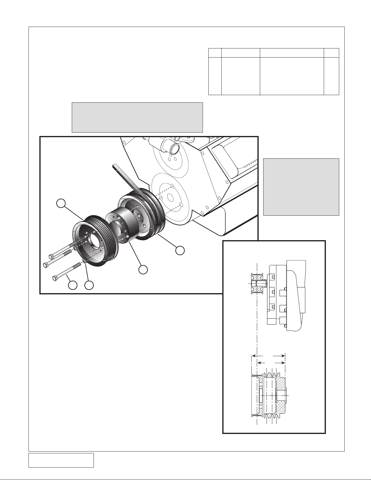
2. CRANK PUllEY
1
2
3
5
4
4.894
4.094
BALANCER FACE
SUPERCHARGER
BELT CENTERLINE
A. Put the supplied crank pulley, spacer and
V-groove pulley together while lining up the
three mounting holes.
B. Using the 3/8-16 x 4.75" hex head bolts and
3/8" washers, mount the crank pulley assembly to the harmonic balancer. Torque bolts to
35 ft./lbs. (See Fig. 2-a.)
CAUTION: Before installing the crank pulley,
make sure the balancer surface is
flat without burrs or other imperfections that would cause the pulley to
run untrue.
NO. PART DESCRIPTION QTY.
1 4MA018-051 Crank Pulley 1
2 7A375-475 3/8-16 x 4.75" HH Bolts 3
3 7J375-044 3/8" Washers 3
4 4GA018-011 V-Groove Pulley 1
5 4MA017-061 Spacer 1
NOTE: If the pulley
configuration on
your engine
requires a special crank and
pulley (short
water pump,
etc.) use Fig.
2-b as a quideline for proper
pulley spacing.
P/N: 4GA020-030
©2008 Vortech Engineering, LLC
All Rights Reserved, Intl. Copr. Secured
08DEC08 V3.0(BBC LowMount(4GA..030 V3.0))
Fig.2-a
2
Fig.2-b
Page 11
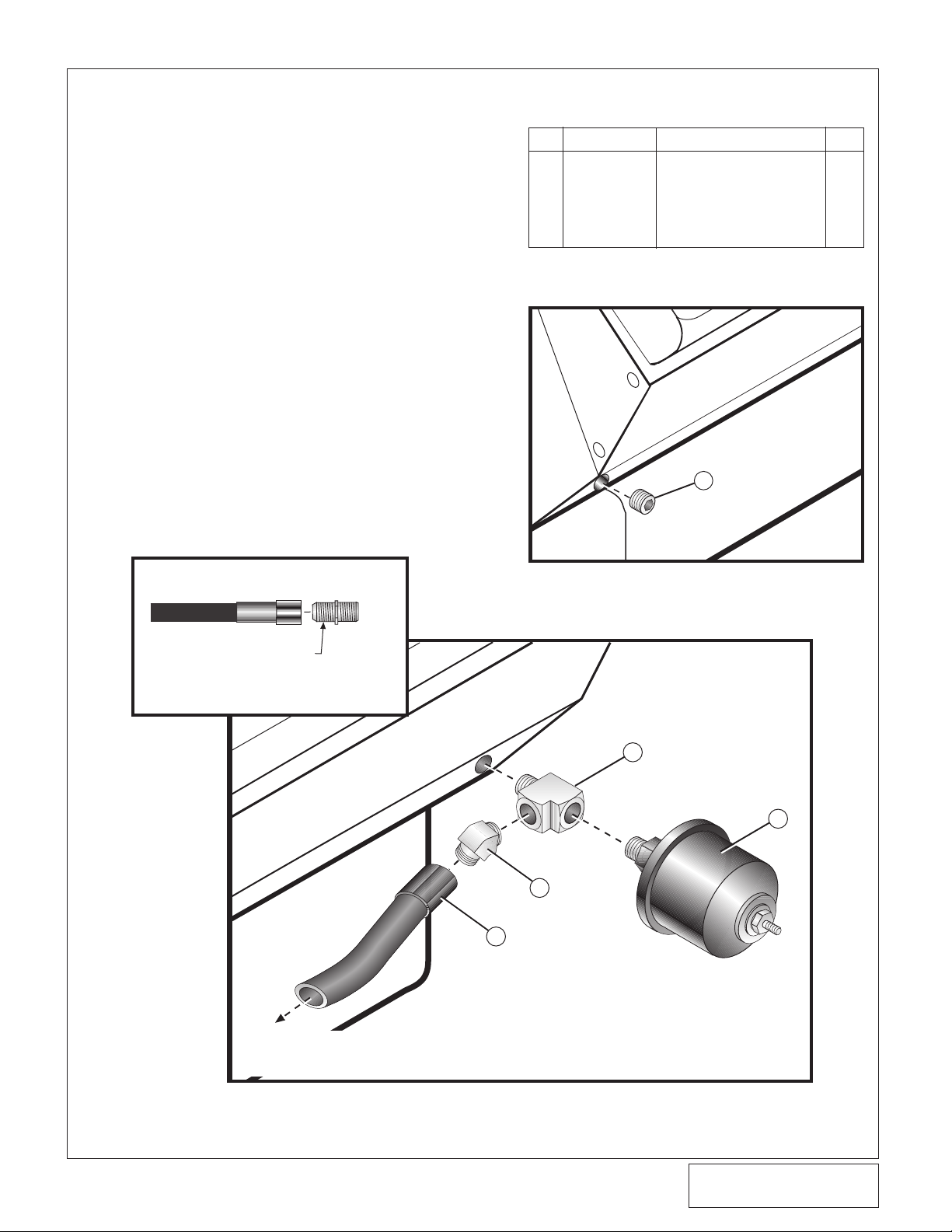
3. SUPERCHARGER OIl FEED
GOES TO
SUPERCHARGER
OIL SUPPLY NOZZLE
3
5
4
2
TYPICAL OIL FITTING ASSEMBLY
• USE ONLY OIL ON FLARE
TYPE FITTINGS. DO NOT
USE TEFLON PASTE OR
TAPE ON FLARE END
1
A. Remove the stock 1/4" hex head pipe plug
from the front left lower portion of the engine
block, if equipped, and replace it with the kit
supplied 1/4" socket head pipe plug.
Replacement of the square head plug allows
for supercharger bracket installation clearance. Apply Teflon paste sparingly to the
plug's threads prior to installation. (See Fig.
3-a.)
B. Remove stock oil pressure transducer, and
install in its place an 1/8" straight "T". Orient
the fitting to allow for suitable installation and
routing of oil supply line. Apply engine oil to
the male thread prior to installation. Next,
install the 1/8"NPT x 45° male elbow into the
side port of the straight "T" (see Fig. 3-b).
Thread one end of the oil feed hose onto the
1/8"NPT x 45° male elbow. Use a small
amount of oil when installing the flare type oil
feed hose assembly. Route the hose towards
the front of the engine; keep the free end
capped to avoid contamination.
NO. PART DESCRIPTION QTY.
1 7P250-120 Socket Head Pipe Plug 1
2 N/A Oil Pressure Transducer 1
3 7P125-034 1/8" Straight “T” 1
4 7P125-103 1/8" NPT x 45° Male Elbow 1
5 4MA145-020 Oil Feed Hose 1
Fig. 3-a
Fig. 3-b
3
08DEC08 V3.0(BBC LowMount(4GA..030 V3.0))
©2008 Vortech Engineering, LLC
All Rights Reserved, Intl. Copr. Secured
P/N: 4GA020-030
Page 12

4. SUPERCHARGER OIl DRAIN
1”
1”
PUNCH HOLE
THROUGH
A. With this option, it is nec-
essary to make a hole in
the oil pan. (See Fig.
4-a.) It is best to punch the
hole rather than drill.
Remove paint from around
the hole area so that it
does not flake into the pan.
B. Make a mark on the oil
pan on the left side ahead
of the oil filter. The mark
should be 1" below the bolt
flange and forward of the
third bolt by 1". You may
choose a different place, if
necessary. However, take
care not to damage any
internal parts. The drain hose should gradually drop with no dips or kinks and should be
above the oil level.
C. Use a small center punch to perforate the
pan and expand the hole. Switch to a larger
diameter punch and expand the hole further
to approximately Ø9/16" (or use an air hammer with a 9/16" round punch attachment).
Most punches are made from hexagon material and may be placed in a socket with an
extension to make this procedure easier.
D. Tap the hole with a 3/8"NPT tap approximate-
ly 1/4" deep. Pack the flutes of the tap with
heavy grease to catch and hold the chips.
Once the tap is removed, it must be cleaned
and repacked before tapping resumes. Use a
small magnet to check for any stray chips in
the threads after completing the tapping procedure.
E. Thoroughly clean the threaded area with ace-
tone or other solvent. Apply a small amount
of silicone sealer to the new threads. Apply a
small amount of silicone sealer to the threads
of the 3/8"NPT hose fitting and secure in the
hole. Make sure a seal is formed all around
the fitting. Allow the sealer to cure completely.
F. Temporarily cover the end of the hose and
secure out of the way. The return is a gravity
drain and should be routed to provide a gradual drop.
G. Drain and replace the engine oil and change
the filter.
Fig. 4-a
P/N: 4GA020-030
©2008 Vortech Engineering, LLC
All Rights Reserved, Intl. Copr. Secured
08DEC08 V3.0(BBC LowMount(4GA..030 V3.0))
4
Page 13
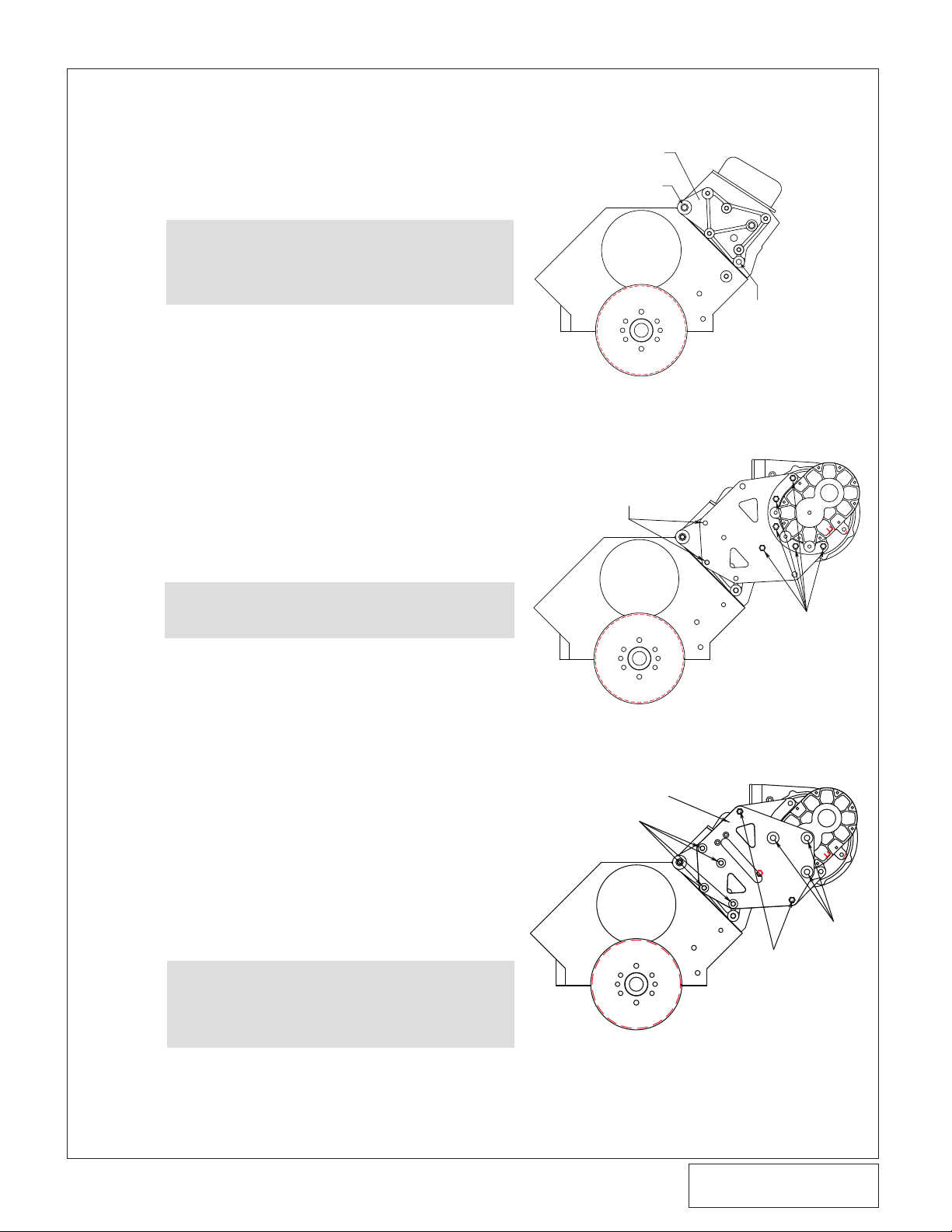
5. SUPERCHARGER MOUNTING (TWIN PlATE v-7 ONlY, v-4 SKIP TO SECTION 8)
TEMPORARILY INSTALL TWO
3/8-16 X 2.75” HEX HEAD SCREWS
3/8-16 X 1.25 HEX
HEAD SCREW AND
WASHER
4GA010-051
3/8-16 X 2.75 HEX HEAD
SCREW AND WASHER
3/8-24 X
2.75” HEX
HEAD
SCREW AND
WASHER
M12 X 1.75 X
20MM HEX
HEAD SCREW
AND WASHER
4GA010-061
7/16-14 X 4.25
HXHD SCREW
VORTECH SUPERCHARGER
MOUNTING BRACKET
2 PLACES 7/16-14 x 2" SH SCREW
A. Mount the supplied aluminum supercharger
mounting bracket onto the front of the driver’s
side cylinder head using the two 7/16-14 x 2"
socket head screws and one 7/16-14 x 4.25"
screw with washer as shown in Fig. 5-a.
NOTE: Some Gen IV and earlier heads (includ-
B. Loosely attach the supplied supercharger
mounting plate (4GA010-051) to the previously installed mounting bracket using one of
the supplied 3/8-16 x 1.25” hex head screw
and washer as shown in fig. 5-b. Temporarily
install two of the supplied 3/8-16 x 2-3/4” hex
head screws through the supercharger
mounting plate as a guide. Tighten the 3/8-16
x 1.25” hex head screw at this time. Remove
the two 3/8-16 x 2-3/4” hex head screws.
C. Remove the blue plastic oil drain cap located
on the fitting at the bottom of the supercharger unit and install the supplied 1/2" (fabric
braided) oil drain hose. Secure with a #8
hose clamp.
ing “GM performance” heads) require
3/8-16 screws and flat washers to be
used in lieu of the 7/16" hardware. Both
sizes have been included in the mounting bracket assembly.
Fig. 5-a
D. Install the supercharger to the mounting
E. Loosely install the supercharger support plate
F. Route the drain hose down to the previously
CAUTION: Clock the clamp screw housing to the
side so that it does not interfere with
the mounting plate during installation.
plate. Secure the unit to the plate with the
five supplied 3/8-16 x 1.25" screws and AN
flat washers.
(4GA010-061) using the four 3/8-16 x 2.75”
screws, washers and four of the Ø.75” x
1.309” long spacers (2A017-049) provided.
Install the two remaining Ø.75” x 1.309” long
spacers (2A017-049) using the two 3/8-24 x
2.75” screws and washer. Finally install the
three M12-1.75 x 20mm thin head screws
with washers as seen in figure 5-e. Tighten
all hardware installed to this point.
installed fitting in the oil pan and secure with
a #8 hose clamp. Trim hose if necessary.
NOTE: Oil drain hose must be routed downhill
with minimal bends and no kinking. The
supercharger relies on a gravity drain for
proper operation. Uphill hose routing will
result in improper drainage and possibly
supercharger failure.
Fig. 5-b
Fig. 5-E
5
08DEC08 V3.0(BBC LowMount(4GA..030 V3.0))
©2008 Vortech Engineering, LLC
All Rights Reserved, Intl. Copr. Secured
P/N: 4GA020-030
Page 14

5. SUPERCHARGER MOUNTING, CONT'D (TWIN PlATE v-7 ONlY, v-4 SKIP TO
SECTION 8)
G. Install the supplied 1/8"NPT x 90° x #4 fitting
into the supercharger oil feed nozzle. Do not
use teflon tape on the threads or oil feed
blockage may result.
CAUTION: Ensure that the oil supply system is
H. Carefully route the previously installed oil feed
hose up to the supercharger oil feed fitting
taking care not to kink the hose. Carefully
thread the hose end onto the feed fitting.
LIGHTLY LUBRICATE THE FITTING WITH
ENGINE OIL.
free of contamination that might plug
the supercharger oil inlet orifice. Hold
the supercharger oil feed fitting with
wrench while tightening the oil feed
line fitting.
P/N: 4GA020-030
©2008 Vortech Engineering, LLC
All Rights Reserved, Intl. Copr. Secured
08DEC08 V3.0(BBC LowMount(4GA..030 V3.0))
6
Page 15

6. ACCESSORY DRIvE BElTS (TWIN PlATE v-7 ONlY, v-4 RACE SKIP TO
SECTION 8)
NOTE: Belts are to be sized per each application and
purchased separately and are not included in this
base kit.
A. Install the correct length V-belts onto the
water pump, power steering and crank pulleys.
B. Tighten all bracket hardware that was
“snugged” earlier and adjust/tighten the
V-belts making sure all belts are routed correctly. Make sure all hoses and wiring are
routed correctly and secured, that all coolant
modifications are complete and hose clamps
are properly tightened.
7
08DEC08 V3.0(BBC LowMount(4GA..030 V3.0))
©2008 Vortech Engineering, LLC
All Rights Reserved, Intl. Copr. Secured
P/N: 4GA020-030
Page 16

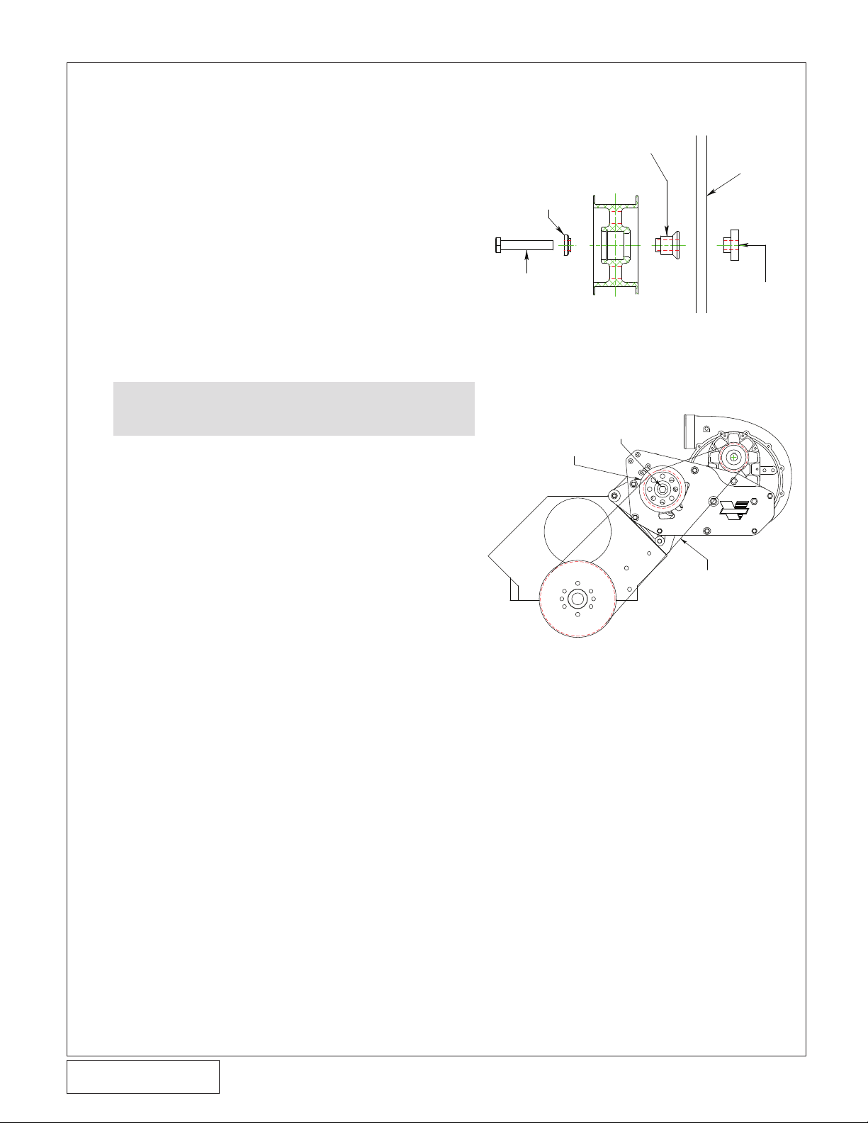
7. SUPERCHARGER DRIvE BElT INSTAllATION
ALUMINUM TENSIONER IDLER
1/2”-20 HEX NUT AND BEARING
PILOT (4DF017-011)
SUPERCHARGER DRIVE
BELT (INSTALLED AFTER
ACCESSORY BELTS)
4GA010-061
1/4-20 X 1” SCREW
ARBOR SPACER
(SLIDES OVER ARBOR)
IDLER
BEARING
PILOT
1/2”-20
HEX NUT
IDLER
SPACER
1/2” MOUNTING PLATE
IDLER
ADJUST
SCREW
BELT TENSIONER ARBOR
IDLER ADJUST
SCREW BRACKET
(TWIN PlATE v-7 ONlY, v-4 RACE SKIP TO SECTION 8)
CAUTION: Cog tensioner assembly does not use the ten-
sioner arbor method. For cog drive applications
skip to 7-e
A. Attach the supplied belt tensioner adjustment
screw, tensioner arbor and adjustment screw
locator block to the supercharger support
plate as show in figure 7-a. Secure the
assembly to the plate by threading the two
1/4-20 x 1” flat head allen screws through the
plate and into the adjustment screw locator
block as shown.
B. Slide the arbor bushing (Ø.75”OD x Ø.530”ID
x .490” long) onto the arbor screw. Verify that
the bushing fits in the arbor slot up against
the arbor screw head. Place the idler spacer
(4GA017-011) and aluminum tensioner idler
onto the arbor screw, secure using the provided bearing pilot (4FD017-011) and supplied 1/2"-20 hex nut.
C. Fit the supercharger drive belt over the new
crank pulley and supercharger pulley.
D. Tension the belt by using a 3/8” socket to
turn the tensioner adjustment screw anticlockwise until the desired tension is
achieved. Secure the tensioner idler by tightening the 1/2"-20 hex nut previously installed.
Fig. 7-a (10-Rib Belt Route Only)
P/N: 4GA020-030
©2008 Vortech Engineering, LLC
All Rights Reserved, Intl. Copr. Secured
08DEC08 V3.0(BBC LowMount(4GA..030 V3.0))
Fig. 7-b (10-Rib Belt Tensioner Assembly - Side View)
8
Page 17

M12 X 1.75 X 65MM BOLT
BEARING
PILOT
IDLER
IDLER
SPACER
MACHINE NUT SPECIAL
(PILOTS IN SLOT)
1/2” MOUNTING PLATE
4GA010-061
7. SUPERCHARGER DRIvE BElT INSTAllATION, CONT'D
(TWIN PlATE v-7 ONlY, v-4 RACE SKIP TO SECTION 8)
E. (Cog drive only) Slide the M12-1.75 X 65mm
screw through the supplied bearing pilot, aluminum idler and idler spacer. Place the
machine nut into the slot in the supercharger
support plate. Loosely attach the previously
assembled idler assembly, do not tighten at
this time. See Fig. 7-c.
F. (Cog drive only) Fit the supercharger drive
belt over the new crank pulley, idler pulley
and supercharger pulley.
G. (Cog drive only) Tension the belt by pulling
up on the tensioner by hand and then tighten
the previously installed M12 hardware. The
belt does not need to be tightened excessively. See Fig. 7-d.
CAUTION: Do not "back-bend" a cog belt to tension.
Fig. 7-c (Cog Belt Tensioner Assembly - Side View)
Fig. 7-d (Cog Belt Route Only)
9
08DEC08 V3.0(BBC LowMount(4GA..030 V3.0))
©2008 Vortech Engineering, LLC
All Rights Reserved, Intl. Copr. Secured
P/N: 4GA020-030
Page 18

8. SUPERCHARGER MOUNTING RACE (v-4 RACE BRACKETS ONlY. TWIN PlATE
3/8-16 x 1.25”
HEX HEAD
SCREW AND
WASHER
TEMPORARILY INSTALL
TWO 3/8 X 2.75” HEX
HEAD SCREWS
4GA010-071
3/8-16 X 2.75” HEX
HEAD SCREW AND
WASHER
M12 X 1.75 X
20MM HEX
HEAD SCREW
AND WASHER
3/8-16 X 3.0”
HEX HEAD
SCREW AND
WASHER
4GA010-081
®
7/16-14 X 4.25
HXHD SCREW
VORTECH SUPERCHARGER
MOUNTING BRACKET
2 PLACES 7/16-14 x 2" SH SCREW
v-7 SKIP TO SECTION 11)
A. Mount the supplied aluminum supercharger
mounting bracket onto the front of the driver’s
side cylinder head using the two 7/16-14 x 2”
socket head screws and one 7/16-14 x 4.25”
screw with the washer as shown in Fig. 8-a
NOTE: Some Gen IV and earlier heads (includ-
ing “GM performance” heads) require 3/816 screws and flat washers to be used in
lieu of the 7/16” hardware. Both sizes
have been included in the mounting
bracket assembly.
B. Loosely attach the supplied supercharger
mounting plate (4GA010-071) to the previously installed mounting bracket using one of the
supplied 3/8-16 x 1.25” hex head screws and
washer as shown in fig. 8-b. Temporarily
install two of the supplied 3/8-16 x 2-3/4”hex
head screws through the supercharger
mounting plate as a guide. Tighten the 3/8-16
x 1.25” hex head screw at this time. Remove
the two 3/8-16 x 2-3/4” hex heads screw.
C. Secure an oil drain line to the bottom of the
supercharger in a manner that will not interfere with the supercharger support bracket.
NOTE: There is no oil drain line supplied in
the Race bracket kit.
D. Install the supercharger to the mounting plate.
Secure the unit to the plate with the eight supplied 3/8-16 x 1.25” screws and AN flat washers. See Fig. 8-b
E. Loosely install the supercharger support plate
(4GA010-081) using the five 3/8-16 x 2.75”,
three 3/8-16 x 3” screws, eight Ø1.309” long
spacers (2A017-049) and washers provided.
Finally install the three M12-1.75 x 20mm thin
headed screws as seen in figure 8-c. Tighten
all hardware installed to this point.
F. Route the oil drain hose down to your prede-
termined location and secure.
Fig. 8-A
Fig. 8-B
P/N: 4GA020-030
©2008 Vortech Engineering, LLC
All Rights Reserved, Intl. Copr. Secured
08DEC08 V3.0(BBC LowMount(4GA..030 V3.0))
NOTE: You will need to provide and adequate oil
drain from the supercharger to the oil pan
or oil collection reservoir. The oil path
should maintain a down hill direction and
be free of any dips or kinks. The oil
should enter the pan/reservoir above the
oil level to maintain a free flowing path.
Fig. 8-C
10
Page 19

9. ACCESSORY DRIvE BElTS (v-4 "RACE" ONlY)
NOTE: Belts are to be sized per each application and
purchased separately and are not included in this
base kit.
A. Install the correct length V-belts onto the
water pump, power steering and crank pulleys.
B. Tighten all bracket hardware that was
“snugged” earlier and adjust/tighten the
V-belts making sure all belts are routed correctly. Make sure all hoses and wiring are
routed correctly and secured, that all coolant
modifications are complete and hose clamps
are properly tightened.
11
©2008 Vortech Engineering, LLC
All Rights Reserved, Intl. Copr. Secured
08DEC08 V3.0(BBC LowMount(4GA..030 V3.0))
P/N: 4GA020-030
Page 20
M12 X 1.75 X 65MM LONG
SCREW BEARING PILOT, SPACER,
AND SPECIAL MACHINED NUT
ALUMINUM TENSIONER IDLER
SUPERCHARGER DRIVE BELT
(INSTALLED AFTER
ACCESSORY BELTS)
M12 X 1.75 X 65MM BOLT
BEARING
PILOT
IDLER
IDLER
SPACER
MACHINE NUT SPECIAL
(PILOTS IN SLOT)
1/2” MOUNTING PLATE
10. SUPERCHARGER DRIvE BElT INSTAllATION (v-4 "RACE" ONlY)
A. (Cog drive only) Slide the M12-1.75 X 65mm
screw through the supplied bearing pilot, aluminum idler and idler spacer. Place the
machine nut into the slot in the supercharger
support plate. Loosely attach the previously
assembled idler assembly, do not tighten at
this time. See Fig. 10-a
B. (Cog drive only) Fit the supercharger drive
belt over the new crank pulley, idler pulley
and supercharger pulley.
C. (Cog drive only) Tension the belt by pulling
up on the tensioner by hand and then tighten
the previously installed M12 hardware. The
belt does not need to be tightened excessively. See Fig. 10-b.
CAUTION: Do not "back-bend" a cog belt to tension.
Fig. 10-a (Cog Belt Tensioner Assembly - Side View)
P/N: 4GA020-030
©2008 Vortech Engineering, LLC
All Rights Reserved, Intl. Copr. Secured
08DEC08 V3.0(BBC LowMount(4GA..030 V3.0))
Fig. 10-b (Cog Belt Route Only)
12
Page 21

11. AIR INlET SUGGESTIONS
A. As mentioned at the beginning of this manu-
al, no supercharger air inlet components are
included with this kit because of the numerous configurations and different vehicle types
that this kit will be installed on.
B. When “laying out” your supercharger air inlet,
keep in mind that supercharger and engine
performance is greatly increased when a cool
air source is used. Pulling in heated air from
the engine compartment, or from above the
headers will result in lackluster performance
and possible engine detonation.
C. Vortech offers some individual components
that may aid you in your installation (Not
applicable to V-4 "Race" Kit).
• Vortech #7S400-000 Ø4" x 90° cast aluminum
inlet elbow (3.5" CL radius)
• Vortech #7S400-001 Ø4" x 90° rubber inlet
elbow
• Vortech #7S400-200 Ø4" x 2" silicone sleeve
• Vortech #8H040-095 air filter, Ø4" flange x 5"L x
Ø4.5"
• Vortech #8H040-095 air filter, Ø4" flange x 7"L x
Ø5.38"
• Vortech #8H040-095 air filter, Ø4" flange x
7.63"L x Ø5.38"
13
©2008 Vortech Engineering, LLC
All Rights Reserved, Intl. Copr. Secured
08DEC08 V3.0(BBC LowMount(4GA..030 V3.0))
P/N: 4GA020-030
Page 22

12. DISCHARGE DUCTING/CARBURETOR ENClOSURE
A. Install optional Vortech carburetor enclosure
(if not already completed) assembly #8M205-
012. Instructions are included with the enclosure assembly. The enclosure lid is to be
attached to the base with the inlet facing the
passenger’s side of the vehicle.
B. Attach the short 90° aluminum elbow with
flange to the enclosure inlet using the supplied gasket, 5/16-18 x 1 bolts and washers.
C. Install the long 3-1/2" aluminum elbow in
between the supercharger discharge and the
90° flange elbow using the 3.5” sleeve, #56
clamps, #48 clamp and reducer.
NOTE: Depending on the vehicle application
and hood configuration, minor bottom
side hood modifications may be required.
P/N: 4GA020-030
©2008 Vortech Engineering, LLC
All Rights Reserved, Intl. Copr. Secured
08DEC08 V3.0(BBC LowMount(4GA..030 V3.0))
14
Page 23

13. FINAl REASSEMBlY AND CHECK
A. Refit the Radiator fan and shroud, if
equipped.
B. Reconnect the battery.
C. If your vehicle has gone over 15,000 miles
since its last spark plug change, you will need
to change the spark plugs now before test
driving the vehicle.
D. Check all fittings, nuts, bolts and clamps for
tightness. Pay particular attention to oil and
fuel lines around moving parts, sharp edges
and exhaust system parts. Make sure all
wires and lines are properly secured with
clamps or tie-wraps.
E. Check all fluid levels, making sure that your
tank(s) is filled with 91 octane or higher fuel
before commencing test drive.
F. Start engine and allow to idle a few minutes,
then shut off.
G. Recheck to be sure that no hoses, wires, etc.
are near exhaust headers or moving parts
and for signs of any fluid leakage. Re-jet the
carburetor as required. Install a boost referenced high-performance mechanical fuel
pump or high performance electric fuel pump
with boost referenced fuel regulator. Check
ignition timing to make sure it is properly set
before commencing test drive.
H. PLEASE TAKE SPECIAL NOTE: Operating
the vehicle without all sub assemblies completely and properly installed and working
may cause FAILURE OF MAJOR ENGINE
COMPONENTS.
I. Test drive the vehicle.
J. Read the Street Supercharger System
Owner's Manual and RETURN THE Warranty
REGISTRATION FORM within thirty (30)
days of purchasing your supercharger system
to qualify.
WARNING: Do not attempt to operate the vehicle
until all components are installed and
all operations are completed including
final check.
NOTE: Vortech strongly recommends the use of
a wide band O2 sensor to monitor the air
fuel ratio in the exhaust when calibrating
the carburator. A safe air/fuel ratio of
11.0:1 is recommenced when using 91
octane fuel.
15
©2008 Vortech Engineering, LLC
All Rights Reserved, Intl. Copr. Secured
08DEC08 V3.0(BBC LowMount(4GA..030 V3.0))
P/N: 4GA020-030
Page 24

®
ENGINEERING, LLC
1650 PACIFIC AVENUE • CHANNEL ISLANDS, CA 93033-9901 • (805) 247-0226
FAX (805) 247-0669 • www.vortechsuperchargers.com • M-F 8:00 AM - 4:30 PM PST
08DEC08 V3.0(BBC LowMount(4GA..030 V3.0))
©2008 Vortech Engineering, LLC
All Rights Reserved, Intl. Copr. Secured
P/N: 4GA020-030
 Loading...