

Page 1
RACING BYPASS VALVE
ENGINEERING, INC.
NOTE: When installing this unit on Mass Air Flow (MAF)
equipped applications, the bypass discharge MUST be
routed into the supercharger inlet. If the unit is pointed
toward or near the MAF, air turbulence will cause the
MAF meter to send false signals to the ECM resulting in
idle and driveability problems.
MOUNTING:
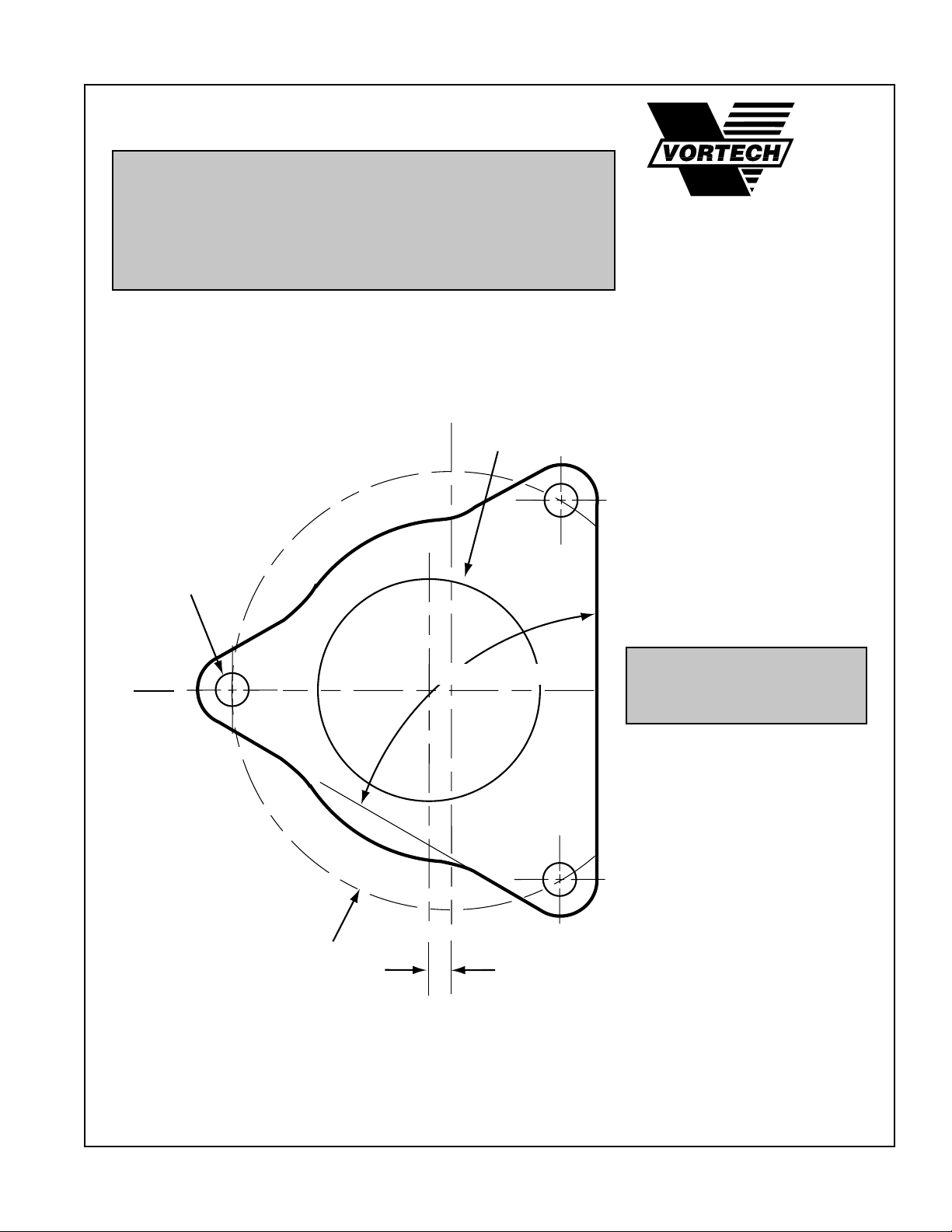
Due to the variety of custom applications, the racing bypass
valve is not a "bolt-on" unit. However, a full scale template with
mounting flange dimensions is shown below:
Ø 2.000
Ø .280 THRU
X 3 PLACES
®
© 1994 VORTECH® ENGINEERING, INC.
all rights reserved
60° X 3 PLACES
Ø 3.70
.190 OFFSET
SETUP:
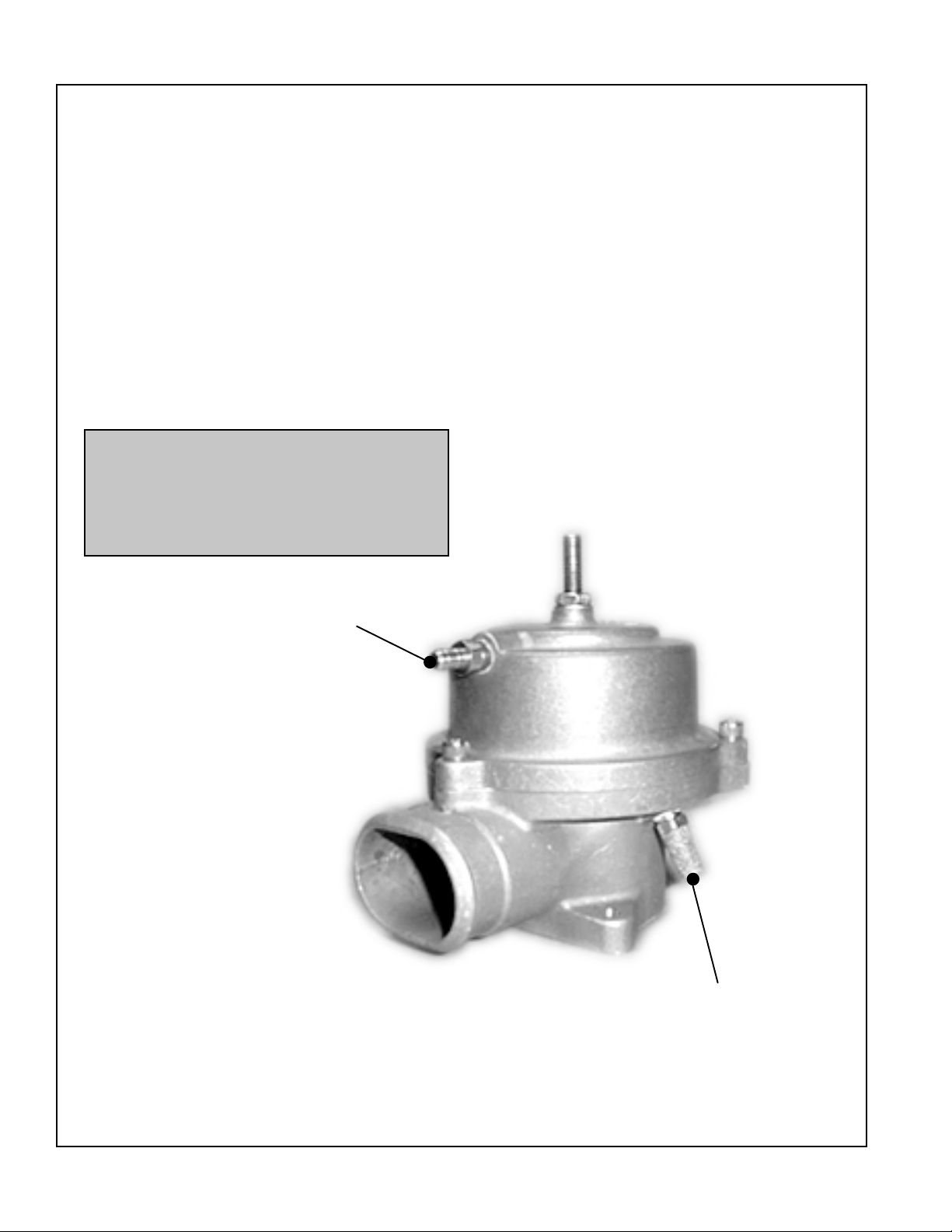
Attach a minimum 1/4" manifold reference line from a vacuum
port on the intake manifold to the 1/4" nipple on racing bypass lid.
(The port must see both vacuum and boost.)
A laser-cut steel valve
flange is available from
V ortech (Part# 8D003-051)
Page 2
RACING BYPASS VALVE, cont'd.
TUNING:
The preload adjustment screw affects the point
at which the bypass valve opens and closes.
Most applications should need no adjustment
and are recommended to use the unit as received (adjustment screw fully extended); this
allows the lightest spring tension, permitting
the valve to open earlier (approximately 4"-5"
Hg) and supplies sufficient force so that the
valve will seal at any amount of boost. Applying more spring pressure will allow it to open
later (approximately eight turns will allow the
valve to open at 9"-10" Hg).
NOTE: It is recommended that the preload screw not be turned in more than 4
turns. At NO time should the screw be
bottomed out. Internal damage may
occur.
REQUIRED: ATTACH A
1/4"MANIFOLD REFERENCE LINE FROM A
V ACUUM PORT ON THE
INTAKE MANIFOLD TO
THE 1/4" BARB (THE
PORT MUST SEE BOTH
V ACUUM AND BOOST).
IMPORTANT: THE DIAPHRAGM VENTS SHOULD
NEVER BE CAPPED OR
PLUGGED. AIR MUST BE
ALLOWED TO MOVE IN AND
OUT OF THE UNIT FOR
PROPER OPERATION.
 Loading...