

Page 1
Maxflow fuel system installation instructions
ENGINEERING, INC.
1986-1993 Ford 5.0 Mustang
WARNING: Keep a fire extinguisher handy and use extreme
caution when dealing with fuel and fuel system components.
Make sure that all work outlined below is performed in a well
ventilated work area, away from any possible flame or spark.
Vortech Engineering, Inc. is not responsible for engine or vehicle damage due to fuel leakage, fire or pump failures.
NOTE: Make sure that the fuel level is below 1/4 tank for easier
installation
A. Component removal/Preparation
1. Disconnect the negative cable from the battery. Secure cable so that it
will not accidentally fall back onto the battery terminal.
2. Disconnect the factory fuel feed and return lines from the fuel rail using
a springlock disconnect tool. Remove the fuel rail extension tubes that
connect the rail (feed and return) to the body mounted fuel lines.
3. Remove the upper intake manifold.
4. Raise the rear of the vehicle and secure with two 2-ton jackstands. Drop
down the fuel tank by loosening the filler neck and removing the two tank
support straps. Unplug the wiring harness attached to the body.
Temporarily remove the tank vent hose.
5. Disconnect and remove the original flexible feed and return lines running
to the tank. Separate both lines from the vehicle.
6. Unplug the factory harness that connects to the in-tank fuel pump (NOT
the fuel level sending unit harness). Using electrical tape, wrap the
exposed end of the harness to protect the contacts from grounding out
on the body or fuel tank. Use tie-wraps to secure the now unused fuel
pump harness to the fuel level sending unit harness.
7. Spray the top of the fuel pump (not yet removed from the tank) with
aerosol brake cleaner so that no dirt or debris will fall into the tank when
the pump is removed. Remove the factory intank fuel pump assembly
and set aside.
8. Locate the four supplied aluminum Y-block adapters in the Maxflow fuel
system kit. Using pipe thread sealant, install one each of the supplied
1/8” NPT pipe plugs into the 1/8” NPT port on the top of each of the Yblocks. Set aside the prepared Y-blocks for future use.
®
© 1998 VORTECH® ENGINEERING, INC.
all rights reserved
1
Page 2
B. Fuel Rail/Injector installation
1. Disconnect the fuel injector wiring connectors and remove
the existing fuel rails. Remove fuel injectors from manifold
base and set aside.
2. Attach the four (4) supplied mounting tabs and eight (8)
#10-24 screws to the fuel rail. Orient the tabs so that the
slot angle is parallel with the injector bores. The tabs are
designed to allow adjustment to compensate for various
injector heights and manifold tolerances.
3. Apply a small amount of oil on supplied fittings and O-rings.
Install into the rails as shown in the fuel system schematic on
page 6.
NOTE: Fuel rails are designed to accept -6 straight
thread O-ring fittings (9/16-18). Attempting to attach
pipe thread (NPT) fittings or any type other than
described above will result in damaged threads and
possible fuel leakage.
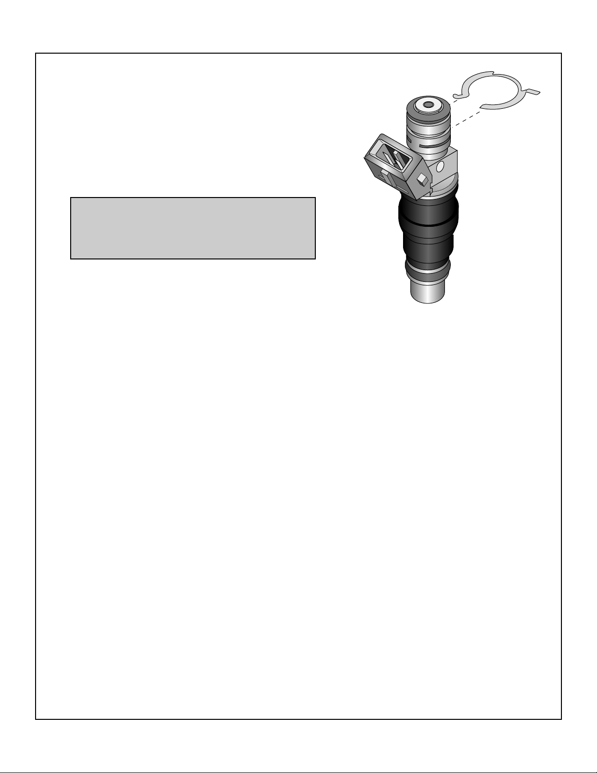
4. Snap the supplied retainers into the top groove on each fuel
injector as shown at the right. Lubricate the injector
O-rings with a small amount of oil. Insert the injectors into the
fuel rail until the retainer is seated.
5. Install both of the fuel rail/injector assemblies onto the mani-
fold base (the longer rail with the hex plug at the front is to be
installed on the driver's side to provide clearance for distributor). Secure rails onto the manifold using the four (4) supplied
1/4-20 socket head screws and mounting tabs (previously
attached to fuel rail).
SNAP THE SUPPLIED RETAINER
ON THE TOP GROOVE OF THE
INJECTOR
2
Page 3
C. Fuel pump and fuel filter mounting/Feed hose
NOTE: Uncut bulk length hose has been supplied in
this kit to allow for minor variances in each installation. The fuel system schematic on page 6 shows the
intended layout of fittings, hose ends and general
hose lengths (study over diagram before proceeding). Actual hose length may vary slightly due to
installer and/or vehicle setup. Use the lengths shown/
given as a guideline. Measure between the fittings
that are to be connected before cutting hose.
1. Insert the supplied fuel tank pickup unit and o-ring into fuel
pump opening in the top of the fuel tank and secure with the
factory retention ring (the fuel pickup is designed to be
installed without a strainer attached).
2. Slide the supplied 12” long piece of -10 “push-on” hose onto
the supplied -10 x 120° hose end. Attach the -10 x 120° hose
end with hose attached to the tank pickup. The fitting should
be flat and parallel to the tank and point toward the rear of the
vehicle. Tighten (until snug) the fitting to the pickup.
NOTE: When assembling blue “push-on” hose and
hose ends, use a light amount of oil to lubricate the
inside of the hose and hose end nipple to allow for
easier assembly. Push the hose onto the hose end
until the hose contacts the plastic stop on the hose
end. Pressure check the hose to twice the maximum
operating pressure. See the last page of this instruction sheet for “braided” hose/hose end assembly.
3. Attach one of the supplied -6 straight hose ends into the end
of the supplied length of -6 hose. Attach hose end to the -6
fitting on the tank pickup and tighten until snug. The hose must
be routed toward the front of the vehicle when the tank is reinstalled.
4. Reinstall the fuel tank and filler tube. While lifting the tank,
reconnect the tank vent hose and secure. Reconnect the fuel
level sending unit harness (if disconnected). Take care to
route the fuel lines and vent line away from exhaust pipes and
sharp edges. Provide room so that the lines are not crushed
between the floor pan and the tank.
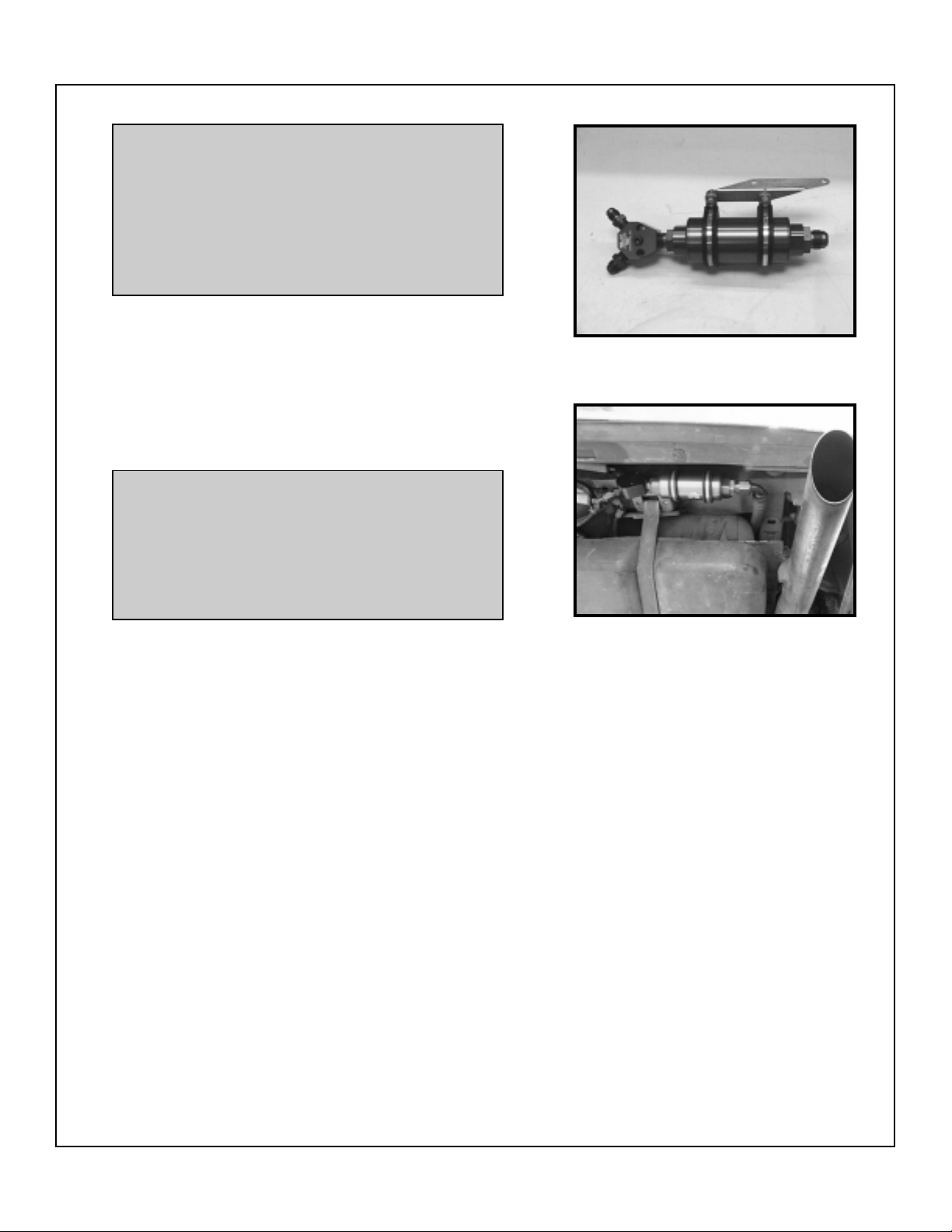
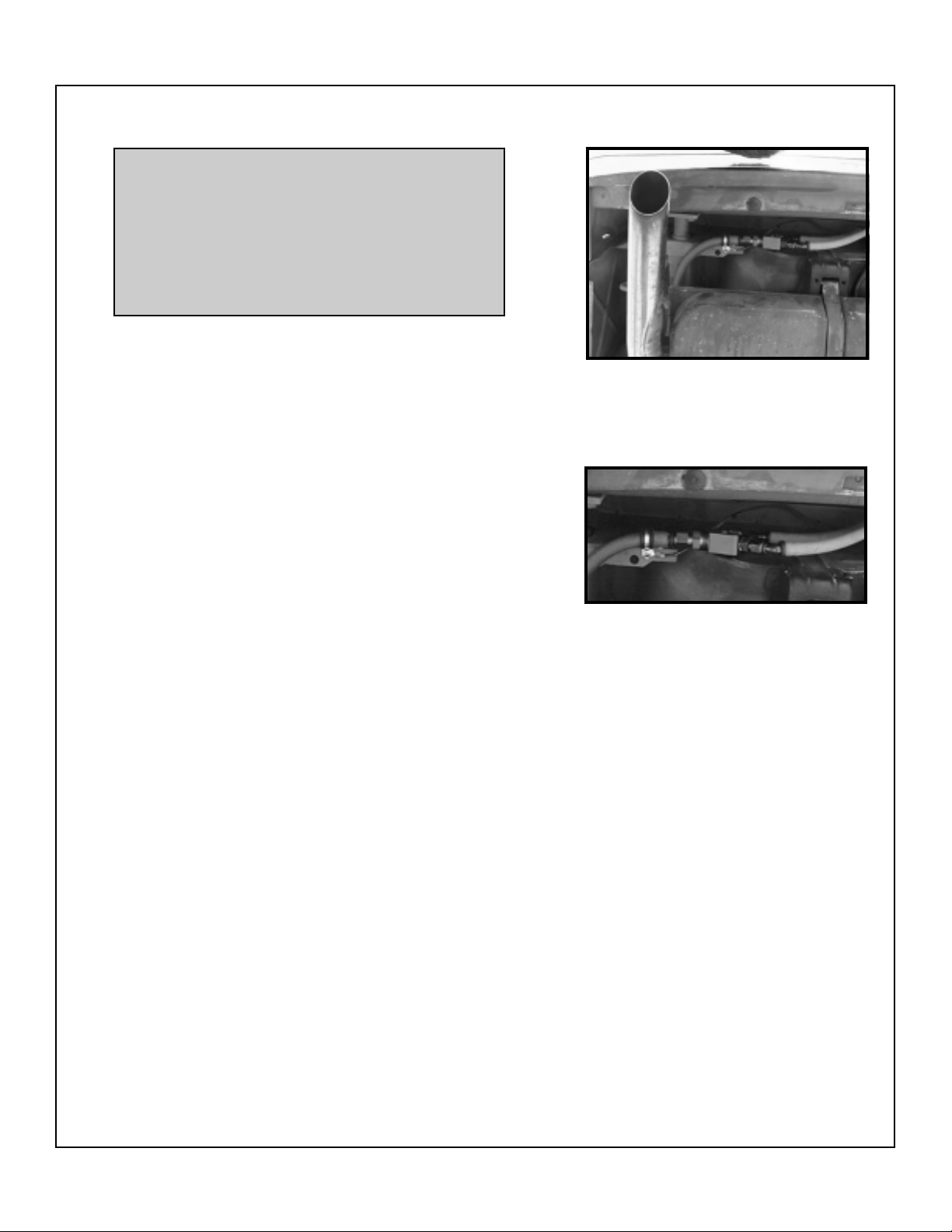
5. Assemble the fuel filter and two -10 o-ring fittings as shown in
the fuel system schematic (Make sure that the 3/8” NPT x -10
fitting with o-ring is in the discharge end of the fuel filter. The
discharge end is the end that does not have the spring).
• Assemble the two 1/4 NPT x -6 fittings into one of the
previously plugged Y-blocks (use a small amount of pipe
sealant on the threads of all pipe fittings). Thread the Y-block
assembly onto the 3/8” NPT x -10 fitting previously attached
to the fuel filter (see Photo 1).
• Use the supplied 1/4” nuts, bolts, washers and clamps to
attach the supplied filter mounting bracket to the fuel filter as
shown in Photo 1.
• Temporarily thread the supplied -10 x 90° hose end onto the
fuel filter inlet. Take the fuel filter/bracket/Y-block assembly
and place it up against the outside bottom of the floor pan of
the trunk (see Photo 2). Line up (left to right) the 90° filter inlet
fitting to the -10 hose coming from the tank pickup so that a
“straight shot” from the tank pickup hose is obtained with a
Photo 1
Photo 2
3
Page 4
C. Fuel pump and fuel filter mounting/Feed hose, (cont'd.)
minimum bend (the hose length may need slight trimming so
that the hose remains straight when it is installed onto the
filter with 90° hose end).
• Using the filter bracket as a guide, mark two spots where the
holes are to be drilled to mount the filter bracket. Centerpunch
and drill the marks with a .14 drill. Mount the filter and bracket
to the body using the two supplied #12 hex head sheetmetal
screws.
• Orient the filter assembly so that the Y-block sits vertical
and points toward the center of the vehicle (see schematic).
• Remove the -10 x 90° hose end from the filter inlet and slide
into the -10 hose coming from the tank pickup. Reattach the
90° hose end and hose to the filter inlet and secure.
6. Cut two 6” lengths of the supplied blue "push-on" -6 hose and
attach one end each to two of the supplied -6 x 45° "push-on"
hose ends (see outlet side of filter in schematic). Attach both
of these hose assemblies to the -6 fittings on the filter Y-block.
7. Attach the T-Rex fuel pumps to the supplied pump mounting
bracket using the pump clamps and #10 x 1/2” bolts, nuts and
washers (see schematic for proper orientation).
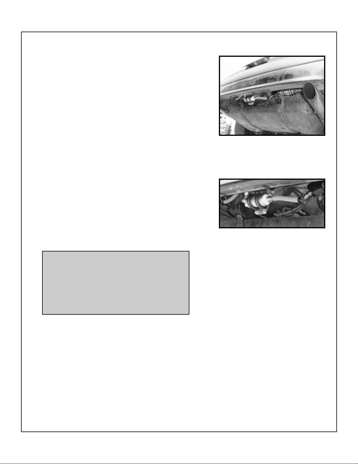
8. Temporarily position the pump bracket assembly up to the
rear/outer spare tire well to allow points to be marked for
mounting holes. Using the rear bumper as a reference,
center the pump assembly (left to right) in the car. Also make
sure that the pumps are located in the proper vertical (up and
down) position (see Photo 3). When the pumps are properly
positioned, the center of both pumps together must line up
with the fuel filter centerline (see schematic). With the
pumps in position, mark and center punch the four mounting
holes. Drill through with a 3/16” drill.
Photo 3
Photo 3.1 - Close up
NOTE: Marking and drilling the four mounting holes
may be done two ways. (1) Remove the bumper
cover and bumper and then mark and drill using the
bracket as a template. (2) Mark two holes on the
outside of the spare tire well with a scribe or felt pen
and then measure from the outside floor bottom to
the mark. Using that same measurement, but from
the inside floor bottom, mark the four holes by using
the pump bracket as a template.
9. Attach the four supplied rubber isolator mounts into the four
remaining holes in the fuel pump mounting bracket (opposite
side of the bracket from the fuel pumps) using the #8 nuts and
washers. Mount the pump bracket assembly to the outside
rear spare tire well through the previously drilled holes (make
sure that the rubber mounts are sandwiched between the
body and the mounting plate) and secure with the # 8 nuts
and washers from the inside of the trunk.
10. Slide the two blue "push-on" -6 pump inlet hoses onto the fuel
pump inlet fittings. Trim the hose length if necessary. Secure
hoses with the two supplied # 4 hose clamps.
11. Cut two 7” lengths of the supplied -6 hose and attach one end
each to two of the supplied -6 x 120° hose ends (see outlet
side of fuel pump in schematic). Attach both of these hose
assemblies to the -6 fittings on the discharge side of the fuel
pumps.
4
Page 5
C. Fuel pump and fuel filter mounting/Feed hose, (cont'd.)
NOTE: Depending on how the pumps were oriented
in their clamps on installation, they may need to be
rotated. When looking at the end of the fuel pumps
from the driver side of the vehicle, the fuel pumps
should be clocked so that the discharge fittings
point up in approximately the one or two o’clock
position (do not allow for the discharge fitting of the
lower pump to contact the electrical terminals of the
upper fuel pump or the bumper).
12. Assemble the pump discharge Y-block assembly as before except
with two 1/4” NPT x -6 fittings and one 3/8” NPT x -8 fitting. Connect
the Y-block assembly to the two fuel pump discharge hoses using two
of the supplied -6 x 45° hose ends (see schematic).
13. Attach one of the supplied -8 straight hose ends into the supplied
length of -8 hose. Attach hose end assembly onto the -8 flare fitting
located in the pump discharge Y-block (see Photo 4). Route the
remaining length (approximately 15 feet) of hose around the fuel tank
and up to the rear of the passenger side front fenderwell. Do not yet
cut the hose.
• Route the hose in such a manner so that large radius bends are
maintained (tight bends will cause severe flow restriction and possible hose damage). Avoid sharp edges and hot mufflers/pipes etc.
Make sure that the hose has adequate clearance to allow for proper
up and down axle and driveshaft movement. Do not route the hose
down the driveshaft tunnel.
• Attach the hose to the bottom of the floor pan using the supplied
isolator clamps (use only half of the supplied clamps for the feed
hose; the remaining clamps will be used for the return hose) and #12
Phillips head sheetmetal screws. The hose should be routed
outboard of the vehicles’ subframe connectors, if equipped, to protect
the hose in the event of a driveline failure.
14. Temporarily remove the passenger side plastic inner fender liner.
Prepare the supplied fuel rail feed Y-block with the same fittings as
the pump discharge Y-block (3/8” NPT x -8 and two 1/4” NPT x -6
fittings). The Y-block assembly will be attached inside the upper
corner portion of the passenger side inner fender (outside of the
engine compartment), slightly above the plastic inner fender liner
(when installed), next to the factory steel brake line. Mock-up the
entire assembly (-8 feed hose, -8 straight hose end and Y-block
assembly) to determine the amount of hose (if any) to be removed
from the feed hose to achieve a smooth, kink-free hose route.
15. Connect the -8 hose end to the feed hose. Attach the hose assembly
to the Y-block. Cut two 32” (or longer if needed) pieces of -6 hose and
connect one end of each hose to two of the supplied -6 x 90° hose
ends.
• Temporarily connect the hose assemblies to the rear of each fuel
rail on the intake manifold. Clock the 90° hose ends so that they point
down and over to the passenger side of the vehicle.
• Route the hoses out of the engine compartment through the factory
opening in the rear of the passenger side shock tower. To verify
proper hose length, temporarily attach one each of the supplied -6
hose ends (90° and 45°) to the Y-block (see diagram).
• Route the lines into the inner fender and to the hose ends (make
sure hoses are routed smoothly without sharp bends). Make sure
that the hose is correct. Mark hose for trimming, if necessary.
Photo 4
Photo 4 - Close up
5
Page 6
C. Fuel pump and fuel filter mounting/Feed hose, (cont'd.)
FUEL SYSTEM
➛
FRONT OF
VEHICLE
-6 X 34" LONG HOSE
SCHEMATIC
-6 X 22" LONG HOSE
NOTE: DO NOT Pre-cut hose. Uncut bulk
length hose has been supplied in this kit to
allow for minor variances in each installation. The schematic shows the intended
layout of fittings, hose ends and general
hose lengths (study over diagram before
proceeding). Actual hose length may vary
slightly due to installer and/or vehicle setup.
Use the lengths shown/given as a guideline. Measure between the fittings that are
to be connected before cutting hose.
VORTECH
-6 X 32" LONG HOSE
-8 X 15' LONG HOSE
VORTECH
-6 RETURN HOSE
-6 O-RING (7 PLACES)
-6 X 32" LONG HOSE
-6 X 200" LONG HOSE
FUEL TANK PICKUP
FUEL REGULATOR
ADAPTER
SPLICE IN FMU HERE
(IF USED)
-6 X 7" LONG HOSE
-6 X 7" LONG HOSE
-6 X 6" LONG 'PUSHON' HOSE
-6 X 6" LONG 'PUSHON' HOSE
6
-10X 12" LONG 'PUSHON' HOSE
-10 O-RING (2 PLACES)
Page 7
D. Fuel rail return/Fuel regulator block mounting
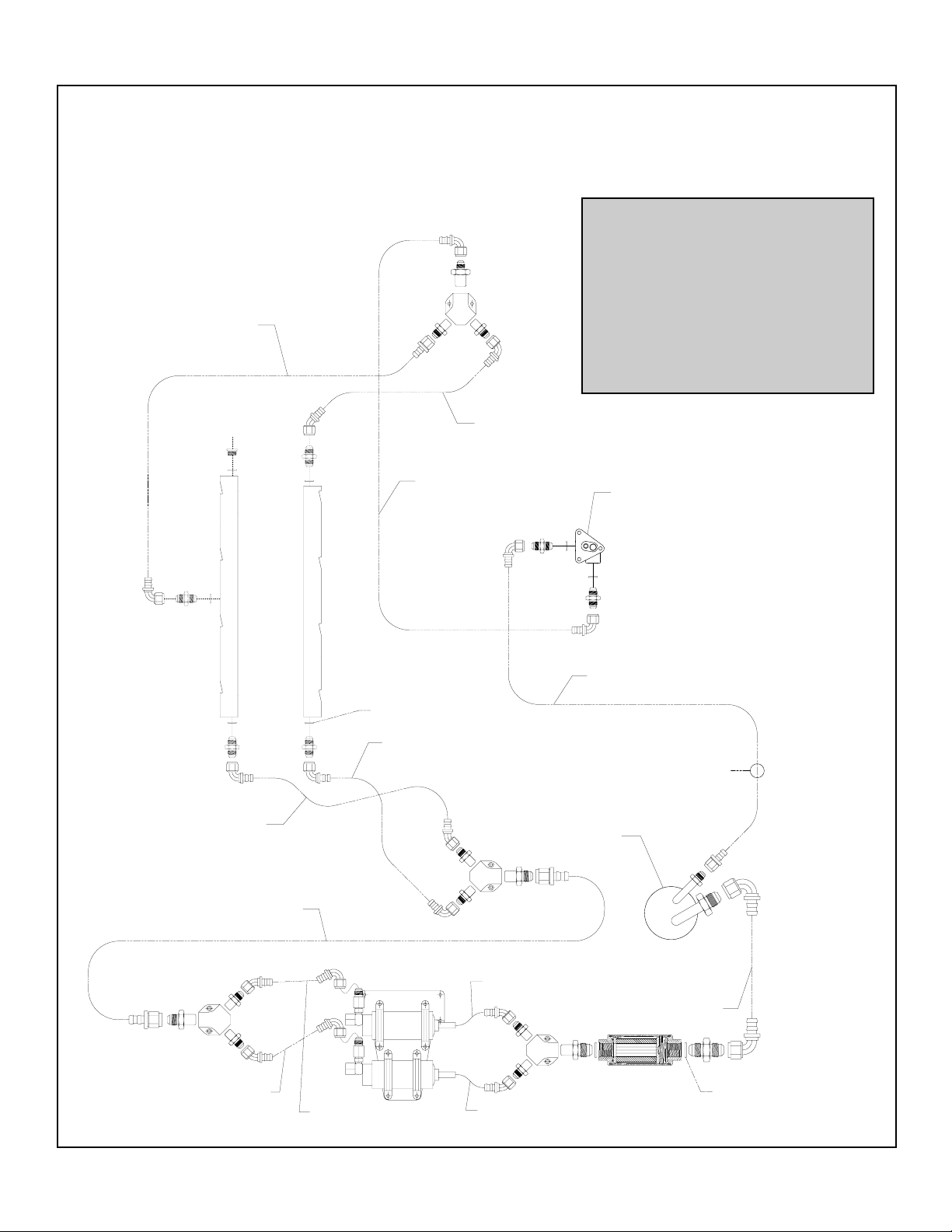
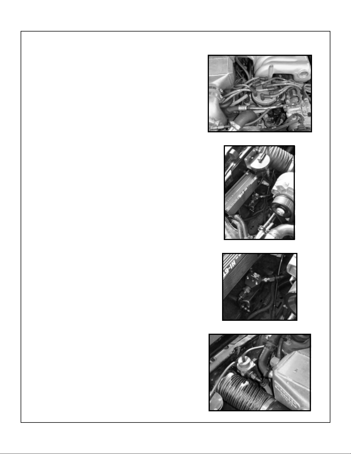
1. Cut a 34” (or longer if needed) piece of hose from the supplied
bulk length of -6 hose. Attach one of the supplied -6 x 90°
hose ends onto the end of the hose. Attach the hose to the
fitting located on the bottom of the driver side fuel rail. Route
the hose assembly around the front of the distributor (see
Photo 5) and down to the passenger side of the engine
compartment where the factory air filter box was originally
located.
2. Cut a 22” (or longer if needed) piece of hose from the supplied
bulk length of -6 hose. Attach one of the supplied -6 x 45°
hose ends onto the end of the hose. Attach the hose to the
fitting located on the front end of the passenger side fuel rail.
Route the hose assembly down to the passenger side factory
airbox location.
3. Assemble the last Y-block using two supplied 1/4” NPT x -6
fittings and one 3/8” NPT x -6 fitting (the 1/8” NPT port at this
location is where a fuel pressure gauge tap should be
located).
• Mount the Y-block assembly to the flat, horizontal portion
inner fender (see Photo 6) with the single port pointing to the
front of the vehicle.
• Attach one of the supplied -6 straight hose ends to the return
hose coming from the driver side rail (cut hose length if
necessary).
• Attach one of the supplied -6 x 90° hose ends to the hose
coming from the passenger side rail (cut hose length if
necessary).
• Attach the hose assemblies to the mounted Y-block in the
port locations shown in the schematic.
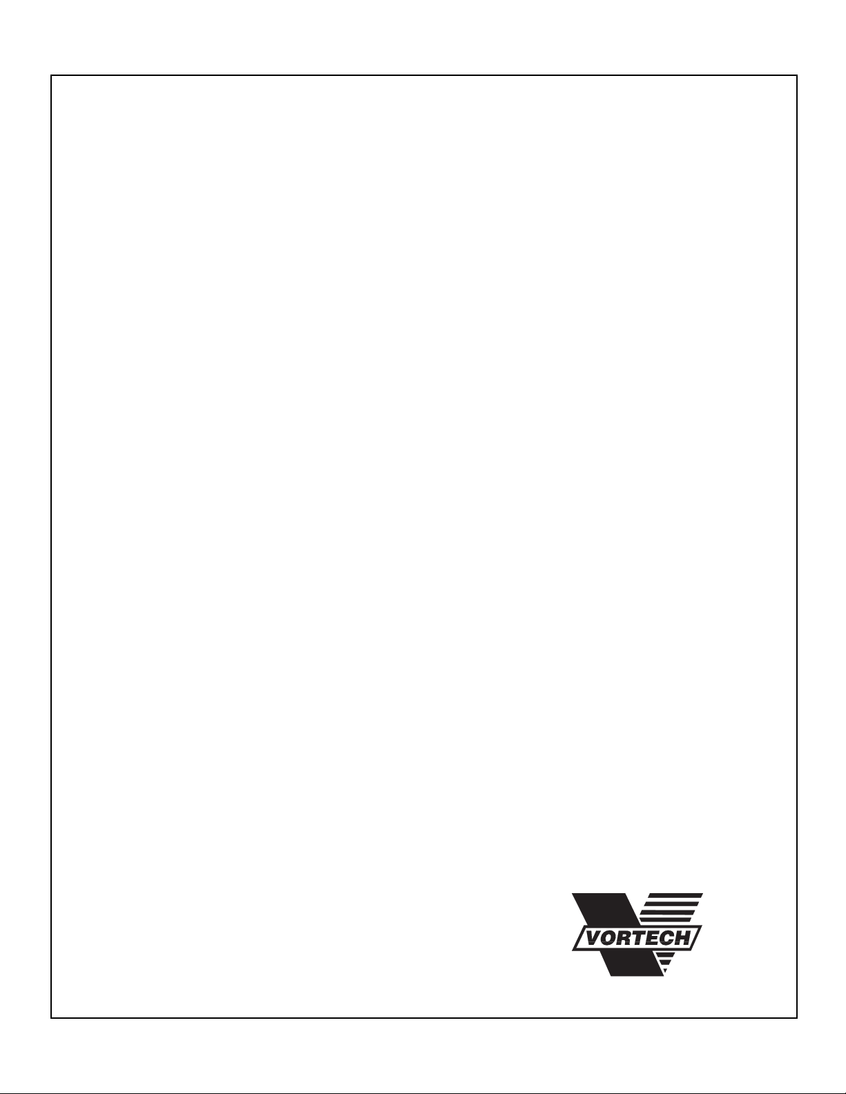
4. Mount the existing fuel pressure regulator to the supplied fuel
pressure regulator adapter using the original hardware.
Mount the regulator and adapter to the supplied mounting
bracket using the supplied 10-24 x 3/8” socket head bolts.
Find a location on the side of the inner fender to mount the
regulator (see Photo 7). Mark and drill holes for the regulator
assembly using the bracket as a guide. Mount the bracket to
the inner fender using the two supplied #10 phillips head
sheetmetal screws.
5. Attach one -6 x 90° hose end to the front Y-block port and one
to the fuel regulator inlet port. Measure the length of hose that
will be required to connect the two hose ends (approximately
23”). Remove the hose ends, attach one to each end of the
cut hose and reattach to the Y-block and regulator inlet port.
6. Route the -6 return hose (from the tank) up to the fuel
regulator outlet port. Cut hose length if necessary and attach
one of the supplied -6 x 90° hose ends to the hose. Connect
the hose assembly to the regulator return fitting.
7. Connect the regulator vacuum port to manifold vacuum. If an
FMU is to be used, insert it in between the fuel regulator outlet
and the fuel return hose to the tank.
Photo 5
Photo 6
Photo 6.1 - Close up
Photo 7
7
Page 8

E. Fuel pump wiring
1. Mark and drill two .14 fuel pump relay mounting holes in the
interior of the trunk, close to the factory fuel pump harness
located in the right rear of the vehicle (the upper edge of the
spare tire well works well).
2. Following the fuel pump wiring diagram, wire the pumps and
relays. Make sure that all ground locations are free from paint
and dirt and maintain a solid metal-metal contact.
3. Route the supplied 12 gauge wires (from relay terminal #30)
to the (+) terminal on the battery or to the (+) lug on the starter
solenoid. Make sure that both power wires and 20 amp fuses
are used. Do not combine both wires into one wire unless
larger (8 ga. minimum) wire is used.
4. Using one of the supplied wire taps, combine both of the
yellow (relay trigger harness) wires together. Attach the
combined wires to the factory trigger wire (red/purple) in the
factory fuel pump harness using another wire tap.
GROUND
(-)
T-REX™ FUEL PUMP
(+)
87
20A
fuse
GROUND
87a
86
RELAY WIRING SCHEMATIC
30
GROUND
85
87
87a
86
RELAY WIRING SCHEMATIC
30
85
(-)
T-REX™ FUEL PUMP
(+)
20A
fuse
RED/PURPLE WIRE IN
STOCK HARNESS
(Check with test light. When key
is turned to “ON” position, test
light should illuminate for 2-3
seconds & then should turn
“OFF” automatically.)
(+)
(-)
8
Page 9
ENGINEERING, INC.
F. Final Check/Reassembly
1. With all hose fittings connected and secure, “key-on” the ignition
several times in sequence or until normal fuel rail pressure is
reached (35-45 psi). Thoroughly check over the entire installation for fluid leakage. Make sure that all fuel injectors are dry
where they are inserted into the fuel rail.
2. Check that all hoses are routed securely away from heat and
sharp corners. Do not allow fuel lines to chafe/rub on each other
or anything else. Find and correct any problems or leaks.
3. Reinstall the intake manifold and other components that may
have been removed before installation.
4. Start and idle the vehicle. Double check the installation for fluid
leaks.
Supplement for Stainless steel braided hose/hose
end assembly
(only for use with stainless steel hose and hose ends)
1. Wrap the hose tightly with electrical tape at the center of the cut
location (this minimizes braid flare when cutting). Cut the hose
square (through the center of the tape) using a thin, high speed
cut-off wheel (best) or fine tooth hacksaw. Remove the tape after
cutting being careful not to fray the braid.
2. Slip the cut hose end into the hose end socket (socket must be first
separated from the nipple portion of the hose end). Use a twisting,
pushing motion until hose opening is in line with the back of the
threads inside the hose end socket.
3. IMPORTANT - Mark the socket base where it meets the hose with
a felt pen. This mark will later let you know if the socket has pulled
out during hose assembly in the next few steps.
4. Liberally lubricate the nipple threads and inside of hose with 30 wt.
oil. While gently holding the socket and hose assembly in a vise
and by hand, carefully insert the nipple into the hose. Turn
(clockwise) the nipple by hand into the socket and hose to engage
the nipple and socket threads. Make sure hose does not push out
of socket by observing the mark made in previous step. Thread
the nipple in by hand as far as possible. Make sure threads are
mated properly and not crossthreading.
5. Using a wrench, complete the hose end assembly. When properly
assembled, a small gap of .030 or less should exist between the
socket and the shoulder of the nipple.
6. IMPORTANT - Check the pen mark made on hose in step 3 for
hose pushout. Hose assembly should be cleaned and tested to
twice the maximum operating pressure. Hose should also be
double checked at time of installation for leakage under normal
operating conditions.
®
© 1998 VORTECH® ENGINEERING, INC.
all rights reserved
9
 Loading...