

Page 1
®
GM 5.3L&6.2L
Light Truck/SUV
2007-2008 Model Years
Supercharger System
Installation Instructions
50 State Smog Legal per CARB EO #D-213-27
ENGINEERING, LLC
1650 Pacific Avenue, Channel Islands CA 93033-9901 • Phone: 805 247-0226
Fax: 805 247-0669 • www.vortechsuperchargers.com • M-F 8:00AM - 4:30PM (PST)
DP/N: 4GL020-018 - v2.0 11/11/08
Page 2

FOREWORD
STOP
his manual provides information on the installation, maintenance and service
of the Vortech supercharger kit expressly designed for this vehicle. All infor-
T
mation, illustrations and specifications contained herein are based on the latest product information available at the time of this publication. Changes to the
manual may be made at any time without notice. Contact Vortech Engineering for
any additional information regarding this kit and any of these modifications at (805)
247-0226 8:00am-4:30pm PST.
Take note of the following before proceeding:
1. Proper installation of this supercharger kit requires general automotive mechanic knowledge and experience. Please browse through
each step of this instruction manual prior to beginning the installation
to determine if you should refer the job to a professional installer/
technician. Please contact your dealer or Vortech Engineering for
possible installers in your area.
2. This product was designed for use on stock (un-modified, OEM) vehicles.
The PCM (computer), engine, transmission, drive axle ratios and tire O.D. must
be stock. If the vehicle or engine has been modified in any way, check with
Vortech prior to installation and use of this product.
3. Use only premium grade fuel with a minimum of 91 octane (R+M/2).
4. Always listen for any sign of detonation (knocking/pinging) and discontinue hard
use (no boost) until the problem is resolved.
5. Vortech is not responsible for any clutch, transmission, drive-line or engine
damage.
P/N: 4GL020-018
©2008 Vortech Engineering, LLC
All Rights Reserved, Intl. Copr. Secured
11NOV08 GM Trk/H2(4GL..018v2.0)
Exclusions from Vortech warranty coverage considerations
include, but not limited to:
1. Neglect, abuse, lack of maintenance, abnormal operation or improper installation.
2. Continued operation with an impaired vehicle or sub-system.
3. The combined use of Vortech components with other modifications such as, but
not limited to, exhaust headers, aftermarket camshafts, nitrous oxide, third party
PCM programming or other such changes.
©2008 VORTECH ENGINEERING, LLC
All rights reserved. No part of this publication may be reproduced, transmitted, transcribed, or translated
into another language in any form, by any means without written permission of Vortech Engineering, LLC.
ii
Page 3

TABLE OF CONTENTS
FOREWORD ................................................................ii
TABLE OF CONTENTS . . . . . . . . . . . . . . . . . . . . . . . . . . . . . . . . . . . . . . . . . . . . . . . . . . . . . . .iii
IMPORTANT NOTES . . . . . . . . . . . . . . . . . . . . . . . . . . . . . . . . . . . . . . . . . . . . . . . . . . . . . . . . iv
TOOL & SUPPLY REQUIREMENTS . . . . . . . . . . . . . . . . . . . . . . . . . . . . . . . . . . . . . . . . . . . . .v
PARTS LIST (2007-2008 GM 5.3L Truck) ........................................ vi
PARTS LIST (2007-2008 GM 5.3L Truck, Flex Fuel) . . . . . . . . . . . . . . . . . . . . . . . . . . . . . . . viii
PARTS LIST (2008 6.2L Escalade) ..............................................x
1. COMPONENT REMOVAL .................................................1
2. SUPERCHARGER MOUNTING BRACKET ...................................2
3. FUEL INJECTOR REPLACEMENT . . . . . . . . . . . . . . . . . . . . . . . . . . . . . . . . . . . . . . . . .3
4. SUPERCHARGER INSTALLATION . . . . . . . . . . . . . . . . . . . . . . . . . . . . . . . . . . . . . . . . .4
5. FAN SHROUD MODIFICATION . . . . . . . . . . . . . . . . . . . . . . . . . . . . . . . . . . . . . . . . . . . .5
6. INLET DUCT INSTALLATION ..............................................6
7A. RADIATOR TUBE INSTALLATION (5.3L) .....................................7
7B. RADIATOR TUBE INSTALLATION (6.2L) .....................................8
8. CHARGE COOLER INSTALLATION . . . . . . . . . . . . . . . . . . . . . . . . . . . . . . . . . . . . . . . .9
9. SUPERCHARGER BYPASS INSTALLATION . . . . . . . . . . . . . . . . . . . . . . . . . . . . . . . . 11
10. SURGE TANK AND RESERVOIR TANK INSTALLATION . . . . . . . . . . . . . . . . . . . . . . . 13
11A. WATER COOLER INSTALLATION (GM Pickup Truck) . . . . . . . . . . . . . . . . . . . . . . . . . 15
11B. WATER COOLER INSTALLATION (Escalade) ................................16
12A. CHARGE COOLER HOSE ROUTING (GM Pickup Truck) . . . . . . . . . . . . . . . . . . . . . . 19
12B. CHARGE COOLER HOSE ROUTING (Escalade) .............................21
13. WATER PUMP WIRING . . . . . . . . . . . . . . . . . . . . . . . . . . . . . . . . . . . . . . . . . . . . . . . . . 23
14. HOOD HINGE SPRING REPLACEMENT (Escalade) . . . . . . . . . . . . . . . . . . . . . . . . . . 25
15. REFLASH COMPUTER . . . . . . . . . . . . . . . . . . . . . . . . . . . . . . . . . . . . . . . . . . . . . . . . . 26
16. FINAL ASSEMBLY AND CHECK . . . . . . . . . . . . . . . . . . . . . . . . . . . . . . . . . . . . . . . . . . 27
©2008 Vortech Engineering, LLC
iii
All Rights Reserved, Intl. Copr. Secured
11NOV08 GM Trk/H2(4GL..018v2.0)
P/N: 4GL020-018
Page 4

IMPORTANT NOTE
This kit requires ECM programming. The hand-held ECM programmer is included in the kit
box.
The hand-held ECM programmer comes with a twelve month limited warranty from the
original date of purchase of your supercharger system (see the Owner’s Manual for
details).
Vortech Engineering is not responsible for engine or ECM damage due to an improperly
installed/mishandled ECM module or ECM.
Vehicles equipped with On-star that have aftermarket stereos will experience problems with
the ability to re-program the vehicle’s ECM. It is necessary to disconnect the aftermarket
stereo from the wiring harness before continuing with the programming procedure.
This product is protected by state common law, copyright and/or patent. All legal rights
therein are reserved. The design, layout, dimensions, geometry and engineering features
shown in this product are the exclusive property of Vortech Engineering. This product may
not be copied or duplicated in whole or part, abstractly or fundamentally, intentionally or fortuitously, nor shall any design, dimension, or other information be incorporated into any
product or apparatus without prior written consent of Vortech Engineering.
P/N: 4GL020-018
©2008 Vortech Engineering, LLC
All Rights Reserved, Intl. Copr. Secured
11NOV08 GM Trk/H2(4GL..018v2.0)
iv
Page 5
2007-2008 GM Light Trucks
®
ENGINEERING, LLC
50 State Legal Per CARB EO D-213-27
Congratulations on selecting the best performing and best backed automotive
supercharger available today... the VORTECH® Supercharger!
Before beginning this installation, please read through this entire instruction booklet and the Street
Supercharger System Owner's Manual which includes the Automotive Limited Warranties Program
and the Warranty Registration form.
Vortech supercharger systems are performance improving devices. In most cases, increases in
torque of 30-35% and horsepower of 35-45% can be expected with the boost levels specified by
Vortech Engineering. This product is intended for use on healthy, well maintained engines.
Installation on a worn-out or damaged engine is not recommended and may result in failure of the
engine as well as the supercharger. Vortech is not responsible for engine damage.
Installation on new vehicles will not harm or adversely affect the break-in period so long as factory
break-in procedures are followed.
For best performance and continued durability, please take note of the following key points:
1. Use only premium grade fuel 91 octane or higher (R+M/2).
2. The engine must have stock compression ratio.
3. If the engine has been modified in any way, check with Vortech prior to using this product.
4. Always listen for any sign of detonation (pinging) and discontinue hard use (no boost) until
problem is resolved.
5. Perform an oil and filter change upon completion of this installation and prior to test driving
your vehicle. Thereafter, always use a high grade SF rated engine oil or a high quality synthetic, and change the oil and filter every 3,000 miles or less. Never attempt to extend the oil
change interval beyond 3,000 miles, regardless of oil manufacturer's claims as potential damage to the supercharger may result.
6. Before beginning installation, replace all spark plugs that are older than 1 year or 10,000
miles with original heat range plugs as specified by the manufacturer and reset timing to factory specifications (follow the procedures indicated within the factory repair manual and/or as
indicated on the factory underhood emissions tag). Do not use platinum spark plugs unless
they are original equipment. Change spark plugs at least every 15,000 miles and spark plug
wires at least every 50,000 miles.
TOOL & SUPPLY REQUIREMENTS
• Factory Repair Manual
• 3/8" Socket and Drive Set: SAE &
Metric
• 1/2" Socket and Drive Set: SAE &
Metric
• 3/8" NPT Tap and Handle
• Adjustable Wrench
• Open End Wrenches: 3/8", 7/16",
1/2", 9/16"
• Springlock 3/8" and 5/8”Fuel Fitting
Disconnect Tool
• Flat #2 Screwdriver
• Phillips #2 Screwdriver
• Silicone Sealer
• Drill Motor
• 1/8", 3/16", 27/64" Drill Bits
• 3/8" Tube Bender
• 3/16" Allen Wrench
• Wire Strippers and Crimpers
• Utility Knife
• Power Steering Pulley/Puller
& Installer
• Pliers
• Power steering pulley install-
er/puller
If your vehicle has in excess of
10,000 miles since its last spark
plug change, then you will also
need:
• Spark Plug Socket
• NEW Spark Plugs
v
©2008 Vortech Engineering, LLC
All Rights Reserved, Intl. Copr. Secured
11NOV08 GM Trk/H2(4GL..018v2.0)
P/N: 4GL020-018
Page 6
2008 6.2L Escalade
®
Part No. 4GL218-350L/358L
ENGINEERING, LLC
PARTS LIST
IMPORTANT: Before beginning installation, verify that all parts are included in the kit. Report any shortages or
damaged parts immediately.
PART NO. DESCRIPTION QTY
008341 VORTECH CHARGE COOLER DECAL 1
008447 1 YR S/C STRT INFO PKG ASY VOR 1
009035 S/C LUBE, BOTTLED, VORT 3-PACK 1
2F328-040 V3 SI-TRIM, 01-08 GM LS TR 3.33 1
2A046-113 BELT, 6 RIB X 112.89 EFFECT. L 1
2A046-140 BELT, 6 RIB X 114.00 EFFECT. L 1
4GL011-021 MOUNTING BRACKET-MACH 1
4GL020-018 INSTALL MANUAL, GM TRK 07/08 1
4GL110-120 HINGE, ASY, 07 GM TRK HOOD 1
4GL010-120 HINGE, 07 GM TRK HOOD, LEFT 1
4GL010-130 HINGE, 07 GM TRK HOOD, RIGHT 1
4FB017-041 LOWER SPACER, ALT. BRACKET 2
4GL112-050 AIR INTAKE ASSY, 04 5.3L GM TR 1
4GL010-011 BRKT,D SIDE GM TRK AIR INLET 1
4GL010-012 BRKT,P SIDE GM TRK AIR INLET 1
4GL012-010 DUCT, INLET, LONG GM SUV/TRK 1
4PGL012-017 DUCT, S/C INLET, 03 ESCALADE 1
7A250-050 1/4-20 X .50 SHCS ZINC PLTD 2
7C060-025 M6 X 1.0 X 25MM HX 2
7J006-093 6MM WASHER, PLATED 2
7J250-001 1/4 WASHER, SAE, PLTD 2
7P156-082 5/32 TEE 1
7P250-045 1/4 MALE NPT X 3/8 MALE BARB 1
7P375-050 3/8" HOSE UNION, BRASS 1
7P375-113 PCV VALVE, VIPER, 3/8"-1/2" BA 1
7R002-016 #16 SAE TYPE F SS HOSE CLAMP 4
7R002-052 #52 SAE TYPE F SS HOSE CLAMP 2
7R002-056 #56 SAE TYPE F SS HOSE CLAMP 3
7R002-060 #60 SAE TYPE F SS HOSE CLAMPS 1
7S350-200 SLEEVE, 3-1/2 X 2, BLUE 1
7S350-300 SLEEVE, 3-1/2 X 3, BLUE 1
7S366-350 SLEEVE, REDUCER 3.66 - 3.50 1
7U030-046 5/32" VACUUM LINE 2.5
7U030-056 3/8 PCV/VAC RUBBER HOSE 3.5
7U033-000 5/8" PCV HOSE 0.16
7U034-016 1" GS HEATER HOSE 0.25
7U035-001 3-1/2" FLEX HOSE 0.75
7U133-045 RUBBR ELBO, 1"DIA X 45 DEG 1
7U375-052 3/8" VACUUM CAP 1
8D001-001 STD COMPRESS BYPASS VALVE 1
4GL114-010 WATER TUBE ASSY, GM TRUCK 1
4GL014-018 WATER TUBE,GM TRUCK,POLISHED 1
7A250-050 1/4-20 X .50 SHCS ZINC PLTD 1
7J006-093 6MM WASHER, PLATED 1
7R002-024 #24 SAE TYPE F SS HOSE CLAMP 2
7R003-022 ADEL CLAMP 1 3/8" 1
7U133-125 HOSE, 1.25DIA 90° LONG LEG 1
5W001-085 SLEEVE, FLEX BRD Ø1.5" NOM. 0.5
4PGL112-070 DISCH ASSY, 07 ESCALADE 1
4GL012-030 ELBOW,3.88"-3.0" X 90º GM TRK 1
4GL012-040 DISCH TUBE A, 6.0 COOLER,CAST 1
4GL012-070 DISCH TUBE B, 07 ESCALADE SAT 1
7R002-044 #44 SAE TYPE F SS HOSE CLAMP 5
7R002-048 #48 SAE TYPE F SS HOSE CLAMP 2
7R002-064 .#64 SAE TYPE F SS HOSE CLAMP 1
7S275-200 SLEEVE, Ø2.75" X 2.00"L, BLUE 2
7S300-275 REDUCER, 3.00-2.75 1
PART NO. DESCRIPTION QTY
5A003-040 DIABLO PRED, 06-07 LS2/LS7 C6 1
8F060-047 FUEL INJ 47LB, DELPHI MULTEC 3 8
8N105-200 WATER TANK ASSY, 07 GM TRUCK 1
2A017-875-08 SPACER, .875 OD X .290 LONG 2
7A250-050 1/4-20 X .50 SHCS ZINC PLTD 4
7J250-001 1/4 WASHER, SAE, PLTD 4
7P375-075 3/4" HOSE BARB UNION, BRASS 2
7P500-026 1/2NPT X 3/4 BARB 90° BRASS 3
7P500-078 1/2NPT X 3/4 HOSE FIT STRT 1
7R007-001 NYLON RATCHET CLAMP 1-1/8" 12
7U030-065 HOSE, 3/4 X 90° RUBBER, SHORT 1
7U038-000 3/4" HEATER HOSE 19
7U038-012 HOSE,3/4"DIA 90°,4X12 LEGS 1
7U038-150 HOSE, 3/4"X150° MOLDED HOSE 1
7U100-055 TIE WRAP, 7.5" NYLON 6
8N010-250 BRKT, SURGE TANK, 07 GM TRK 1
8N010-260 BRKT, COOLANT RES 07 GM TRK 1
8N055-030 TANK, WATER, TRIANGLE SHAPE 1
8N055-050 PLASTIC CAP, SURGE TANK 1
8N056-060 SURGE TANK, PLASTIC 1
8N106-140 WATR COOLR ASY, 07 ESCALADE 1
7A250-050 1/4-20 X .50 SHCS ZINC PLTD 4
7E010-075 #12 X 3/4" SHT METL SCRW HEX 4
7J250-001 1/4 WASHER, SAE, PLTD 8
7R003-016 ADEL CLAMP, 1.0" 1
7U038-012 HOSE,3/4"DIA 90°,4X12 LEGS 1
8N006-020 WATER COOLR, FLDYN DUAL PASS 1
8N010-320 FLDYN BKT, 07 ESCALADE DRVR 1
8N010-330 FLDYN BKT, 07 ESCALADE PASS 1
8N107-050 WATER PMP ASSY, GMT LS1 H.O. 1
5W001-005 3/8" PLASTIC WIRE LOOM 5
5W001-009 16-14GA MALE SLIDE INSULATED 1
5W001-013 14-16 GA BUTT CONN BLU INSUL 4
5W001-014 FUSE HOLDER 10 GA WIRE 1
5W001-015 FUSE, BLADE TYPE 20 AMP 1
5W001-019 10-12 GA BUTT CONN INSULATED 2
5W001-022 T-TAP CONN,14-16 AWG 1
5W001-024 MINI ATC FUSE TAP 1
5W001-041 12-10GA MALE SLIDE INSULATED 2
5W001-043 12-10GA X 1/4" RING TERMINAL 3
7A250-050 1/4-20 X .50 SHCS ZINC PLTD 2
7F250-021 1/4-20 NYLOCK NUT ZINC PLATED 1
7R003-027 ADEL CLAMP,1-11/16" 1
7U100-044 TIE WRAP, 4" NYLON 4
7U100-055 TIE WRAP, 7.5" NYLON 6
8F001-402 PUMP, WATER, PIERBURG 1
8F101-320 FUEL PUMP RELAY ASSY, LS1 TRK 1
5W001-002 FUSE TAP 1
7E010-075 #12 X 3/4" SHT METL SCRW HEX 2
8N201-360 CAC ASY, 07 GM TRUCK 1
2A017-875-13 SPACER, .875 OD X .895 LONG 1
4GL010-110 BRKT, CAC SUPPRT 07 GM TRK 1
7C010-040 M10 X 1.5 X 40 HXHD CL8.8 ZN 1
7J010-002 10MM WASHER, ZINC PLATED 1
7P500-026 1/2NPT X 3/4 BARB 90° BRASS 1
7P500-078 1/2NPT X 3/4 HOSE FIT STRT 1
7U250-200 TAPE, FOAM, 1/4" X 2" X 50' 12
8N101-330 WELDED CORE ASSY, 2007 GM TRK 1
P/N: 4GL020-018
©2008 Vortech Engineering, LLC
All Rights Reserved, Intl. Copr. Secured
11NOV08 GM Trk/H2(4GL..018v2.0)
vi
Page 7
2007-2008 GM 5.3L Truck
®
Part No. 4GL218-360L/368L
ENGINEERING, LLC
PARTS LIST
IMPORTANT: Before beginning installation, verify that all parts are included in the kit. Report any shortages or
damaged parts immediately.
PART NO. DESCRIPTION QTY
4GL011-021 MOUNTING BRACKET 1
8F060-047 FUEL INJECTOR, GM 8.1 DELPHI 8
5A003-040 04-07 GM PREDATOR 1
4GL020-018 INSTALLATION MANUAL 1
009035 S/C LUBE, BOTTLED, 3-PACK 1
4PGL112-020 DISCH ASSY LS1 H.O. TRUCK 1
4GL012-030 ELBOW,3.88”-3.0” X 90º GM TRK 1
4GL012-040 DISCH TUBE A, 6.0 COOLER,CAST 1
4GL012-051 DISCH TUBE B, 6.0 COOLER 1
7R002-044 #44 SAE TYPE F SS HOSE CLAMP 5
7R002-048 #48 SAE TYPE F SS HOSE CLAMP 2
7R002-064 .#64 SAE TYPE F SS HOSE CLAMP 1
7S275-200 SLEEVE, Ø2.75” X 2.00”L, BLUE 2
7S300-275 REDUCER, 3.00-2.75 1
4GL112-050 AIR INTAKE ASSY, 04 5.3L GM TR 1
4GL010-011 BRKT,D SIDE GM TRK AIR INLET 1
4GL010-012 BRKT,P SIDE GM TRK AIR INLET 1
4GL012-010 DUCT, INLET, LONG GM SUV/TRK 1
7A250-050 1/4-20 X .50 SHCS ZINC PLTD 2
7J006-093 6MM WASHER, PLATED 2
7P156-082 5/32 TEE 1
7P250-045 1/4 MALE NPT X 3/8 MALE BARB 1
7P375-050 3/8” HOSE UNION, BRASS 1
7R002-016 #16 SAE TYPE F SS HOSE CLAMP 4
7R002-052 #52 SAE TYPE F SS HOSE CLAMP 2
7R002-056 #56 SAE TYPE F SS HOSE CLAMP 3
7S350-300 SLEEVE, 3-1/2 X 3, BLUE 1
7U030-046 5/32” VACUUM LINE 2.5
7U030-056 3/8 PCV/VAC RUBBER HOSE 3.5
7J250-001 1/4 WASHER, SAE, PLATED 2
7U034-016 1” GS HEATER HOSE 0.25
7U035-001 3-1/2” FLEX HOSE 0.75
7U375-052 3/8” VACUUM CAP 1
8D001-001 STD COMPRESS BYPASS VALVE 1
7U133-045 RUBBR ELBO, 1”DIA X 45 DEG 1
7U033-000 5/8” PCV HOSE 0.16
7P375-113 PCV VALVE, VIPER, 3/8”-1/2” BA 1
4PGL012-017 DUCT, S/C INLET, 03 ESCALADE 1
7S350-200 SLEEVE, 3-1/2 X 2, BLUE 1
7R002-060 #60 SAE TYPE F SS HOSE CLAMPS 1
7C060-025 M6 X 1.0 X 25MM HX 2
4GL114-010 WATER TUBE ASSY, GM TRUCK 1
4GL014-018 WATER TUBE, GM TRUCK POLISHED 1
7A250-050 1/4-20 x .50” SHCS ZINC PLTD 1
7J006-093 6mm WASHER, PLATED 1
7R002-024 #24 SAE TYPE “F” SS HOSE CLAMP 2
7R003-022 ADEL CLAMP 1-3/8” 1
7U133-125 HOSE, Ø1.25” 90° LONG LEG 1
2F338-010 V-3 SC TRIM LS1 TRUCK 1
2A036-312 S/C PULLEY 3.125” 6-GRV 1
7U100-070 KEY, 3/16” SQUARE x 7/8” LONG 1
2A040-011 PULLEY RETAINER S/C 1
7B375-110 3/8-24 x 1” GRADE 8 HXHD 1
7K375-040 3/8”AN960 FLAT WASHER PLATED 1
2A046-113 BELT, K061130-GATES 1
7A375-224 3/8-16 x 2.25” GR5 HX 5
7J375-044 3/8” SAE WASHER, PLTD 5
7C012-050 M12 x 1.75” x 50mm HXHD BOLT 1
4FA016-171 DUST COVER (IDLER PULLEY) 1
4FH016-150 IDLER PULLEY, 6-RIB 3” FLANGED 1
2A017-462 SPACER, IDLER SMOOTH 6-RIB 1
2A046-140 BELT, GATES K061140 1
PART NO. DESCRIPTION QTY
4GL110-010 ASSY, COMPUTER RELOC ‘03 LS1 TR 1
2A017-752-02 SPACER, .750”OD x .894” LONG 2
9AL6061-750 Ø.750” 6061 ALUMINUM ROD 1
7C060-050 M6 x 1.0” 50 HXHD ZINC PLATE 2
7F006-093 6mm NYLOCK NUT 2
7J006-093 6mm WASHER, PLATED 4
8N201-360 CAC ASY, 2007 GMTRUCK 5.3L 1
2A017-875-13 SPACER, .875 OD X .895 LONG 1
9AL6061-0875 7/8” DIA. 6061 ALUMINUM ROD 1.16129
4GL010-110 BRKT, CAC SUPPRT 07 GM TRK 1
7C010-040 M10 X 1.5 X 40 HXHD CL8.8 ZN 1
7J010-002 10MM WASHER, ZINC PLATED 1
7P500-026 1/2NPT X 3/4 BARB 90° BRASS 1
7P500-078 1/2NPT X 3/4 HOSE FIT STRT 1
7U250-200 TAPE, FOAM-1/4” X 2” X 50’ 12
8N101-330 WELDED CORE ASSY, 2007 GM TRK 1
8N101-001 WELDED CORE ASSY W/ENDS ONLY 1
8N002-011 COOLER TANK A, MACHINED 1
8N002-010 COOLER TANK A, CASTING 1
8N002-021 COOLER TANK B, MACH, STD PAT 1
8N002-020 COOLER TANK B, CAST W/HOLES 1
7P062-188 1/16 NPT PIPE PLUG 4
8N003-070 DUCT.COOLER.OUTLET.LS1.FBODY 2
8N003-070R DUCT.COOLER.OUTLET.LS1.FBODY 1
8N105-200 WATER TANK ASSY, 2007 GMTRUCK 1
8N010-250 BRKT, SURGE TANK, 07 GM TRK 1
8N010-260 BRKT, COOLANT RES 07 GM TRK 1
7A250-050 1/4-20 X .50 SHCS ZINC PLTD 4
7J250-001 1/4 WASHER, SAE, PLTD 4
7P375-075 3/4” HOSE BARB UNION, BRASS 3
7P500-026 1/2NPT X 3/4 BARB 90° BRASS 3
7P500-078 1/2NPT X 3/4 HOSE FIT STRT 3
7R007-001 NYLON RATCHET CLAMP 1-1/8” 12
7U030-065 3/4”X90° RUBBER HOSE, SHORT 1
7U038-000 3/4” HEATER HOSE 19
7U038-012 HOSE,3/4”DIA 90°,4X12 LEGS 1
7U038-150 HOSE, 3/4”X150° MOLDED HOSE 1
7U100-055 TIE WRAP, 7.5” NYLON 6
8N055-030 TANK, WATER, TRIANGLE SHAPE 1
8N055-050 PLASTIC CAP, SURGE TANK 1
8N056-060 SURGE TANK, PLASTIC 1
2A017-875-08 SPACER, .875 OD X .290 LONG 2
8N106-160 WATER COOLER ASY, 2007 GM TRK 1
8N010-270 BRKT “A”, HEAT EXCHGR 07 GMT 1
8N010-280 BRKT “B”, HEAT EXCHGR 07 GMT 1
7A250-075 1/4-20 X .75 SHCS PLTD 8
7F250-021 1/4-20 NYLOCK NUT ZINC PLATED 8
7J250-001 1/4 WASHER, SAE, PLTD 16
7R003-016 ADEL CLAMP, 3/4”ID,1/4”EYE 1
7U038-012 HOSE,3/4”DIA 90°,4X12 LEGS 1
7P500-026 1/2NPT X 3/4 BARB 90° BRASS 2
8N006-010 WATER COOLR, SETRAB SINGLE PAS 1
8N107-050 WATER PMP ASSY, GMT LS1 H.O. 1
5W001-005 3/8” PLASTIC WIRE LOOM 5
5W001-009 16-14GA MALE SLIDE INSULATED 1
5W001-013 14-16 GA BUTT CONN BLU INSUL 4
5W001-014 FUSE HOLDER 10 GA WIRE 1
5W001-015 FUSE, BLADE TYPE 20 AMP 1
5W001-019 10-12 GA BUTT CONN INSULATED 2
5W001-022 T-TAP CONN,14-16 AWG 1
5W001-024 MINI ATC FUSE TAP 1
5W001-041 12-10GA MALE SLIDE INSULATED 2
5W001-043 12-10GA X 1/4” RING TERMINAL 3
7A250-050 1/4-20 X .50 SHCS ZINC PLTD 2
7F250-021 1/4-20 NYLOCK NUT ZINC PLATED 1
7R003-027 ADEL CLAMP,1-11/16” 1
7U100-044 TIE WRAP, 4” NYLON 4
©2008 Vortech Engineering, LLC
vii
All Rights Reserved, Intl. Copr. Secured
11NOV08 GM Trk/H2(4GL..018v2.0)
P/N: 4GL020-018
Page 8
2007-2008 GM 5.3L Truck, cont'd
®
Part No. 4GL218-360L/368L
ENGINEERING, LLC
PARTS LIST
IMPORTANT: Before beginning installation, verify that all parts are included in the kit. Report any shortages or
damaged parts immediately.
PART NO. DESCRIPTION QTY
7U100-055 TIE WRAP, 7.5” NYLON 6
8F001-402 PUMP, WATER, PIERBURG 1
8F101-320 FUEL PUMP RELAY ASSY, LS1 TRK 1
5W001-010 16-14GA FEMALE SLIDE INSULATED 2
5W001-016 RELAY,BOSCH 1
5W001-040 12-10GA FEMALE SLIDE INSULATED 2
5W001-042 12-10GA X 3/16” RING TERMINAL 2
5W012-000 12 GA,STRD WIRE, RED 9.5
5W012-000 12 GA,STRD WIRE, RED 1.5
5W012-010 12 GA WIRE BLACK 0.5
5W014-030 14GA STRD WIRE BLACK 0.5
5W016-010 16GA STRD WIRE YELLOW 2.5
5W001-002 FUSE TAP 1
7E010-046 #8 X 3/4 SHEET METAL 2
P/N: 4GL020-018
©2008 Vortech Engineering, LLC
All Rights Reserved, Intl. Copr. Secured
11NOV08 GM Trk/H2(4GL..018v2.0)
viii
Page 9

2007-08 GM 5.3L Truck, Flex Fuel
®
Part No. 4GL218-370L/378L
ENGINEERING, LLC
PARTS LIST
IMPORTANT: Before beginning installation, verify that all parts are included in the kit. Report any shortages or
damaged parts immediately.
PART NO. DESCRIPTION QTY
4GL011-021 MOUNTING BRACKET 1
8F060-008 FUEL INJECTOR, FLEX 8
5A003-040 04-07 GM PREDATOR 1
4GL020-018 INSTALLATION MANUAL 1
009035 S/C LUBE, BOTTLED, 3-PACK 1
4PGL112-020 DISCH ASSY LS1 H.O. TRUCK 1
4GL012-030 ELBOW,3.88”-3.0” X 90º GM TRK 1
4GL012-040 DISCH TUBE A, 6.0 COOLER,CAST 1
4GL012-051 DISCH TUBE B, 6.0 COOLER 1
7R002-044 #44 SAE TYPE F SS HOSE CLAMP 5
7R002-048 #48 SAE TYPE F SS HOSE CLAMP 2
7R002-064 .#64 SAE TYPE F SS HOSE CLAMP 1
7S275-200 SLEEVE, Ø2.75” X 2.00”L, BLUE 2
7S300-275 REDUCER, 3.00-2.75 1
4GL112-050 AIR INTAKE ASSY, 04 5.3L GM TR 1
4GL010-011 BRKT,D SIDE GM TRK AIR INLET 1
4GL010-012 BRKT,P SIDE GM TRK AIR INLET 1
4GL012-010 DUCT, INLET, LONG GM SUV/TRK 1
7A250-050 1/4-20 X .50 SHCS ZINC PLTD 2
7J006-093 6MM WASHER, PLATED 2
7P156-082 5/32 TEE 1
7P250-045 1/4 MALE NPT X 3/8 MALE BARB 1
7P375-050 3/8” HOSE UNION, BRASS 1
7R002-016 #16 SAE TYPE F SS HOSE CLAMP 4
7R002-052 #52 SAE TYPE F SS HOSE CLAMP 2
7R002-056 #56 SAE TYPE F SS HOSE CLAMP 3
7S350-300 SLEEVE, 3-1/2 X 3, BLUE 1
7U030-046 5/32” VACUUM LINE 2.5
7U030-056 3/8 PCV/VAC RUBBER HOSE 3.5
7J250-001 1/4 WASHER, SAE, PLATED 2
7U034-016 1” GS HEATER HOSE 0.25
7U035-001 3-1/2” FLEX HOSE 0.75
7U375-052 3/8” VACUUM CAP 1
8D001-001 STD COMPRESS BYPASS VALVE 1
7U133-045 RUBBR ELBO, 1”DIA X 45 DEG 1
7U033-000 5/8” PCV HOSE 0.16
7P375-113 PCV VALVE, VIPER, 3/8”-1/2” BA 1
4PGL012-017 DUCT, S/C INLET, 03 ESCALADE 1
7S350-200 SLEEVE, 3-1/2 X 2, BLUE 1
7R002-060 #60 SAE TYPE F SS HOSE CLAMPS 1
7C060-025 M6 X 1.0 X 25MM HX 2
4GL114-010 WATER TUBE ASSY, GM TRUCK 1
4GL014-018 WATER TUBE, GM TRUCK POLISHED 1
7A250-050 1/4-20 x .50” SHCS ZINC PLTD 1
7J006-093 6mm WASHER, PLATED 1
7R002-024 #24 SAE TYPE “F” SS HOSE CLAMP 2
7R003-022 ADEL CLAMP 1-3/8” 1
7U133-125 HOSE, Ø1.25” 90° LONG LEG 1
2F338-010 V-3 SC TRIM LS1 TRUCK 1
2A036-312 S/C PULLEY 3.125” 6-GRV 1
7U100-070 KEY, 3/16” SQUARE x 7/8” LONG 1
2A040-011 PULLEY RETAINER S/C 1
7B375-110 3/8-24 x 1” GRADE 8 HXHD 1
7K375-040 3/8”AN960 FLAT WASHER PLATED 1
2A046-113 BELT, K061130-GATES 1
7A375-224 3/8-16 x 2.25” GR5 HX 5
7J375-044 3/8” SAE WASHER, PLTD 5
7C012-050 M12 x 1.75” x 50mm HXHD BOLT 1
4FA016-171 DUST COVER (IDLER PULLEY) 1
4FH016-150 IDLER PULLEY, 6-RIB 3” FLANGED 1
2A017-462 SPACER, IDLER SMOOTH 6-RIB 1
2A046-140 BELT, GATES K061140 1
PART NO. DESCRIPTION QTY
4GL110-010 ASSY, COMPUTER RELOC ‘03 LS1 TR 1
2A017-752-02 SPACER, .750”OD x .894” LONG 2
9AL6061-750 Ø.750” 6061 ALUMINUM ROD 1
7C060-050 M6 x 1.0” 50 HXHD ZINC PLATE 2
7F006-093 6mm NYLOCK NUT 2
7J006-093 6mm WASHER, PLATED 4
8N201-360 CAC ASY, 2007 GMTRUCK 5.3L 1
2A017-875-13 SPACER, .875 OD X .895 LONG 1
9AL6061-0875 7/8” DIA. 6061 ALUMINUM ROD 1.16129
4GL010-110 BRKT, CAC SUPPRT 07 GM TRK 1
7C010-040 M10 X 1.5 X 40 HXHD CL8.8 ZN 1
7J010-002 10MM WASHER, ZINC PLATED 1
7P500-026 1/2NPT X 3/4 BARB 90° BRASS 1
7P500-078 1/2NPT X 3/4 HOSE FIT STRT 1
7U250-200 TAPE, FOAM-1/4” X 2” X 50’ 12
8N101-330 WELDED CORE ASSY, 2007 GM TRK 1
8N101-001 WELDED CORE ASSY W/ENDS ONLY 1
8N002-011 COOLER TANK A, MACHINED 1
8N002-010 COOLER TANK A, CASTING 1
8N002-021 COOLER TANK B, MACH, STD PAT 1
8N002-020 COOLER TANK B, CAST W/HOLES 1
7P062-188 1/16 NPT PIPE PLUG 4
8N003-070 DUCT.COOLER.OUTLET.LS1.FBODY 2
8N003-070R DUCT.COOLER.OUTLET.LS1.FBODY 1
8N105-200 WATER TANK ASSY, 2007 GMTRUCK 1
8N010-250 BRKT, SURGE TANK, 07 GM TRK 1
8N010-260 BRKT, COOLANT RES 07 GM TRK 1
7A250-050 1/4-20 X .50 SHCS ZINC PLTD 4
7J250-001 1/4 WASHER, SAE, PLTD 4
7P375-075 3/4” HOSE BARB UNION, BRASS 3
7P500-026 1/2NPT X 3/4 BARB 90° BRASS 3
7P500-078 1/2NPT X 3/4 HOSE FIT STRT 3
7R007-001 NYLON RATCHET CLAMP 1-1/8” 12
7U030-065 3/4”X90° RUBBER HOSE, SHORT 1
7U038-000 3/4” HEATER HOSE 19
7U038-012 HOSE,3/4”DIA 90°,4X12 LEGS 1
7U038-150 HOSE, 3/4”X150° MOLDED HOSE 1
7U100-055 TIE WRAP, 7.5” NYLON 6
8N055-030 TANK, WATER, TRIANGLE SHAPE 1
8N055-050 PLASTIC CAP, SURGE TANK 1
8N056-060 SURGE TANK, PLASTIC 1
2A017-875-08 SPACER, .875 OD X .290 LONG 2
8N106-160 WATER COOLER ASY, 2007 GM TRK 1
8N010-270 BRKT “A”, HEAT EXCHGR 07 GMT 1
8N010-280 BRKT “B”, HEAT EXCHGR 07 GMT 1
7A250-075 1/4-20 X .75 SHCS PLTD 8
7F250-021 1/4-20 NYLOCK NUT ZINC PLATED 8
7J250-001 1/4 WASHER, SAE, PLTD 16
7R003-016 ADEL CLAMP, 3/4”ID,1/4”EYE 1
7U038-012 HOSE,3/4”DIA 90°,4X12 LEGS 1
7P500-026 1/2NPT X 3/4 BARB 90° BRASS 2
8N006-010 WATER COOLR, SETRAB SINGLE PAS 1
8N107-050 WATER PMP ASSY, GMT LS1 H.O. 1
5W001-005 3/8” PLASTIC WIRE LOOM 5
5W001-009 16-14GA MALE SLIDE INSULATED 1
5W001-013 14-16 GA BUTT CONN BLU INSUL 4
5W001-014 FUSE HOLDER 10 GA WIRE 1
5W001-015 FUSE, BLADE TYPE 20 AMP 1
5W001-019 10-12 GA BUTT CONN INSULATED 2
5W001-022 T-TAP CONN,14-16 AWG 1
5W001-024 MINI ATC FUSE TAP 1
5W001-041 12-10GA MALE SLIDE INSULATED 2
5W001-043 12-10GA X 1/4” RING TERMINAL 3
7A250-050 1/4-20 X .50 SHCS ZINC PLTD 2
7F250-021 1/4-20 NYLOCK NUT ZINC PLATED 1
7R003-027 ADEL CLAMP,1-11/16” 1
7U100-044 TIE WRAP, 4” NYLON 4
©2008 Vortech Engineering, LLC
ix
All Rights Reserved, Intl. Copr. Secured
11NOV08 GM Trk/H2(4GL..018v2.0)
P/N: 4GL020-018
Page 10

07-08 GM 5.3L Truck, Flex Fuel, cont'd
®
Part No. 4GL218-370L/378L
ENGINEERING, LLC
PARTS LIST
IMPORTANT: Before beginning installation, verify that all parts are included in the kit. Report any shortages or
damaged parts immediately.
PART NO. DESCRIPTION QTY
7U100-055 TIE WRAP, 7.5” NYLON 6
8F001-402 PUMP, WATER, PIERBURG 1
8F101-320 FUEL PUMP RELAY ASSY, LS1 TRK 1
5W001-010 16-14GA FEMALE SLIDE INSULATED 2
5W001-016 RELAY,BOSCH 1
5W001-040 12-10GA FEMALE SLIDE INSULATED 2
5W001-042 12-10GA X 3/16” RING TERMINAL 2
5W012-000 12 GA,STRD WIRE, RED 9.5
5W012-000 12 GA,STRD WIRE, RED 1.5
5W012-010 12 GA WIRE BLACK 0.5
5W014-030 14GA STRD WIRE BLACK 0.5
5W016-010 16GA STRD WIRE YELLOW 2.5
5W001-002 FUSE TAP 1
7E010-046 #8 X 3/4 SHEET METAL 2
P/N: 4GL020-018
©2008 Vortech Engineering, LLC
All Rights Reserved, Intl. Copr. Secured
11NOV08 GM Trk/H2(4GL..018v2.0)
x
Page 11

1. COMPONENT REMOVAL
A. Drain a sufficient amount of coolant to allow
for removal of the upper radiator hose and
clamps.
B. Disconnect the negative battery cable.
C. Remove all ducting between the MAF meter
and the throttle body.
D. Remove the upper radiator hose and set it
aside for modification in a future step.
E. Remove the accessory drive belt. (Keep in
the vehicle as a spare.)
F. Remove the idler from the cast bracket and
set aside for later use.
G. The plastic engine covers that extend over
the valve covers (if equipped) will need to be
removed. The upper manifold cover section
may either be removed completely or left in
place and trimmed in order to clear super-
charger componentry.
H. Remove the power steering pump pulley with
a pulley puller. Remove the three bolts secur-
ing the front of the power steering pump.
I. Remove the alternator, bushings and bolts
and set aside for later use. The alternator
bushings can be removed by tapping the
small end through the bracket with an appro-
priately sized socket.
J. Remove the alternator and power steering
pump mounting bracket by removing the
three bolts securing it to the head and the
bottom bolt securing it to the engine block.
K. Remove the oil filler neck and cap from the
passengers side valve cover. Do this by twist-
ing in a counter-clockwise motion. Re-install
the cap directly into the valve corner.
L. Remove retaining clips securing the plastic
cover between the grill and radiator support.
M. Remove the grill by depressing the retaining
clip securing it to the radiator core support.
©2008 Vortech Engineering, LLC
1
All Rights Reserved, Intl. Copr. Secured
11NOV08 GM Trk/H2(4GL..018v2.0)
P/N: 4GL020-018
Page 12
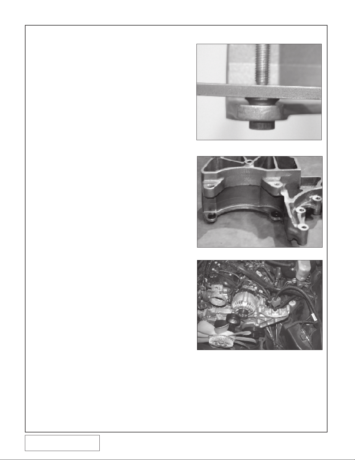
2. SUPERCHARGER MOUNTING BRACKET
A. Install the original alternator bushings into the
supercharger mounting bracket with the
flanged portion pointed back. (See Figs. 2-a,
2-b.)
B. Clean front of driver’s side head of debris.
C. Bolt the supplied Vortech supercharger
mounting bracket to the head and block using
the original mounting bolts. Make sure the
mounting bracket is seated directly on a
machined surface on the head and that no
wires are pinched.
D. Tighten the four mounting bolts to 37 ft-lbs
(50 N-m).
E. Install the two original bolts holding the alter-
nator fusible link junction box in the super-
charger mounting bracket so that it is in the
stock location.
F. Attach the power steering pump to the
Vortech bracket using the original mounting
hardware. Tighten the four power steering
pump bolts to 37 ft-lbs (50 N-m). (One bolt is
still loosely inserted in the engine block.)
G. Reinstall the power steering pump pulley.
Make sure that it is seated flush with the end
of the power steering pump shaft.
H. Reinstall the alternator using the original
hardware. (See Fig. 2-c.)
I. Install the factory idler pulley at the location
shown in Fig. 4-b. Spin the idler to verify that
the rotating portion does not contact the alter-
nator bolt.
Fig. 2-a
Fig. 2-b
P/N: 4GL020-018
©2008 Vortech Engineering, LLC
All Rights Reserved, Intl. Copr. Secured
11NOV08 GM Trk/H2(4GL..018v2.0)
Fig. 2-c
2
Page 13

3. FUEL INJECTOR REPLACEMENT
NOTE: Complete removal of the fuel rail will aid in injector replace-
ment. Separate the fuel rail supply line from the rail using
springlock disconnect tool.
A. Relieve the fuel system pressure.
B. Disconnect the eight fuel injector wiring clips
and retainers from the injectors.
C. Remove the four 10mm bolts holding down
the fuel rail on the intake manifold. Lift up on
the rails evenly, removing all eight injectors.
D. Using a small amount of clean motor oil, light-
ly lubricate the O-rings on both ends of the
Vortech supplied fuel injectors.
E. Install the new injectors into the fuel rails with
the terminals facing outward.
F. Carefully lower the fuel rail/injector assembly
down onto the intake manifold. Check to see
that each injector has been seated properly
into the manifold.
G. Tighten down the fuel rail assembly with the
original bolts and attach the wiring clips to the
injector terminals.
©2008 Vortech Engineering, LLC
3
All Rights Reserved, Intl. Copr. Secured
11NOV08 GM Trk/H2(4GL..018v2.0)
P/N: 4GL020-018
Page 14

4. SUPERCHARGER INSTALLATION
A. Loosely install the supercharger onto the
Vortech bracket. Start all five 3/8-16 x
2-1/4" supercharger mounting screws with
washers.
B. Tighten the supercharger mounting
screws in a rotating pattern to 18 ft-lbs
(25 N-m).
C. Install the Vortech supplied M12 x 50mm
bolt, dust cover, idler pulley and spacer
onto the supercharger cover as shown in
Figs. 4-a, 4-b.
D. Install the supplied supercharger/acces-
sory drive belt per Fig. 4-b.
Fig. 4-a
P/N: 4GL020-018
©2008 Vortech Engineering, LLC
All Rights Reserved, Intl. Copr. Secured
11NOV08 GM Trk/H2(4GL..018v2.0)
Fig. 4-b
4
Page 15

5. FAN SHROUD MODIFICATION
A. Locate the large supplied air inlet duct that will
run across the radiator.
B. Thefanshroudwillneedtobemodiedtoallow
access for mounting of the air inlet duct.
C. Remove the two 13 mm headed bolts retaining
the fan shroud (See Fig 5-a).
D. Using the duct as a template, mark the fan shroud
(See Fig 5-b).
E. Lift up on the fan shroud releasing it from the
lower retaining clips.
F. Using an abrasive cut off wheel remove the lip on
the shroud (See Fig 5-b). Reinstall fan shroud.
G. Reinstall the 13 mm bolts removed earlier.
H. Locate the small angled brackets that will be
attached to the air inlet duct. Using the supplied
hardware, attach the brackets to the duct (See
Fig 5-c).
I. Using the supplied M6 bolts and washers, tempo-
rarily attach the duct to the core support using the
factory weld nuts (See Fig 5-b, c).
J. Trim the fan shroud for the electric fans to gain ac-
cess to the screw locations (See Fig 5-c).
K. Remove the air inlet duct temporarily.
13MM BOLTS TO REMOVE
Fig. 5-a
AREA TO TRIM
WELDNUT LOCATION
FACTORY
SHROUD BOLT
Fig. 5-b
SUPPLIED DUCT
MOUNTING TABS
(LEFT & RIGHT)
SUPPLIED 1/4-20
HARDWARE
AREA TO TRIM
(USE SUPPLIED
6mm HARDWARE)
Fig. 5-c
©2008 Vortech Engineering, LLC
5
All Rights Reserved, Intl. Copr. Secured
11NOV08 GM Trk/H2(4GL..018v2.0)
P/N: 4GL020-018
Page 16

6. INLET DUCT INSTALLATION
A. Install the supplied 3.7"x3.5" reducer sleeve
onto the MAF outlet, and the 3-1/2" x 2"
sleeve on the inlet of the supercharger.
B. Remove any plastic clips that are no longer
used to secure the OEM radiator hose.
C. Slide the entry of the large plastic inlet duct
into the sleeve installed on the MAF (See Fig.
6-a). Lower the inlet duct onto the top of the
radiator shroud.
NOTE: The end of the plastic inlet duct that fits into the MAF sleeve
may require trimming on some applications.
D. Insert the supplied 1/4-20 x 1/2" screws
through the bracket and into each side of the
inlet duct using the supplied washers. Tighten
the screws. (See Fig 6-a.)
E. Using Fig. 6-b, drill a 9/16" hole in the shown
location. Use a 3/8"NPT tap and install the
supplied 3/8" NPT x 3/8" hose barb.
F. Install the supplied 180° inlet duct onto the
inlet of the supercharger after the supercharger is installed. Orient the duct so that it
"swoops" over the side of the supercharger
with the end pointing at the crossover duct.
(See Fig 6-d.)
G. Install the supplied #52 hose clamps and
3-1/2" x 7" long flex hose between the two
ducts previously installed. Trim hose if needed.
H. Use the supplied 3/8" hose from the 3/8" fit-
ting on the inlet duct to the passenger side
valve cover breather hose. Secure the hose
so that it cannot interfere with the throttle arm
or cable. (See Fig 6-c.)
I. Install and tighten the hose clamps on each
connection. (See Fig. 6-a.)
Fig. 6-a
NEW LOCATION
TO DRILL
Fig. 6-b
SUPPLIED
3/8" HOSE
P/N: 4GL020-018
©2008 Vortech Engineering, LLC
All Rights Reserved, Intl. Copr. Secured
11NOV08 GM Trk/H2(4GL..018v2.0)
SUPPLIED 3/8"
RUBBER CAP
Fig. 6-c
Fig. 6-d
6
Page 17

7A. 5.3L RADIATOR TUBE INSTALLATION (5.3L ENGINES ONLY - ALL OTH-
ERS SKIP TO SECTION 7B)
A. Locate the factory upper radiator hose
removed in an earlier step of the installation.
B. Modify the hose by trimmiing the areas noted.
(See Fig.7-a)
C. Using a 2-3" long straight section of the por-
tion of one of the hoses to be discarded,
attach it to the outlet of the radiator and
secure using the factory clamp.
D. Locate the supplied radiator cross-over tube
and attach it to the short hose with the supplied #24 clamp.
E. Use the supplied adel clamp and 1/4-20 x 1/2"
screw and washer to secure the radiator tube
to the insert on the large plastic inlet duct.
(See Fig. 7-c, 7-d.)
F. Slide the length of hose protection sleeve over
the radiator hose in the location shown (See
Fig. 7-d).
G. Attach the modified factory hose to the cross
over tube with a supplied clamp and secure
the other end to the water pump inlet using
the factory clamp (See fig 7-b).
H. Refill the coolant reservoir.
DISCARD THESE
PORTIONS
Fig. 7-a
Fig. 7-b
Fig. 7-c
Fig. 7-d
©2008 Vortech Engineering, LLC
7
All Rights Reserved, Intl. Copr. Secured
11NOV08 GM Trk/H2(4GL..018v2.0)
P/N: 4GL020-018
Page 18

7B. 6.2L RADIATOR TUBE INSTALLATION (6.2L ENGINES ONLY - ALL OTH-
ERS SKIP TO SECTION 8)
A. Locate the factory upper radiator hose
removed in an earlier step of the installation.
B. Modify the hose by trimming the areas noted.
(See Fig.7-a)
C. Using a 3" long straight section of the portion
of one of the hoses to be discarded, attach it
to the outlet of the radiator and secure using
the factory clamp.
D. Locate the supplied radiator cross-over tube
and attach the bent end to the short hose with
the supplied #24 clamp.
E. Use the supplied adel clamp and 1/4-20 x 1/2"
screw and washer to secure the radiator tube
to the insert on the large plastic inlet duct.
(See Fig. 7-e)
F. Cut another 3 inch long straight section from
the factory radiator hose and attach to long
end of the radiator cross over tube.
G. Using the supplied 45 deg hose bend, insert
into the other end of the 3 inch straight piece
installed in the previous step. Connect the
modified factory hose between the opposite
end of 45° elbow and water pump fitting.
Secure with 2 clamps. (See Figure 7-f)
H. Be sure that hose transition is smooth and
free from kinks.
I. Trim radiator hose as required to allow for a
kink free transition of the coolant hose as
shown in figure 7-f.
J. Refill the coolant reservoir.
DISCARD THESE
PORTIONS
Fig. 7-a
Fig. 7-e
P/N: 4GL020-018
©2008 Vortech Engineering, LLC
All Rights Reserved, Intl. Copr. Secured
11NOV08 GM Trk/H2(4GL..018v2.0)
Fig. 7-f
8
Page 19

8. CHARGE COOLER INSTALLATION
A. Remove the screw from the front of the pas-
senger side head. Remove the 10mm nut
located between the middle coil packs on the
passenger side valve cover, below the white
electrical connector. (See Figs. 8-a, 8-b.)
B. Install the charge air cooler support bracket
using the fasteners supplied. (See Figs. 8-a,
8-b.) Apply adhesive foam to the top of the
support bracket where the charge air cooler
rests. Make sure all hoses and wires are
clear from the bracket edges.
NOTE: On later model trucks there will be no EGR assembly. Use the
supplied 10mm x 1.5" screw, washer and .975" spacer in its
place. (See Fig. 8-a.)
C. Slightly bend both the transmission and
engine oil dipsticks up and away to give
clearance for the charge air cooler.
D. Install the nickel plated 1/2"NPT x 3/4 90°
and straight brass fittings into the charge air
cooler using thread sealant on the threads.
(See Fig. 8-d.)
E. Install a 20-inch piece of 3/4 hose to the 90°
fitting and secure with a nylon clamp.
F. Attach the long 90° formed hose to the
straight barbed fitting on the charge cooler.
(See Fig 8-c).
G. Set the charge air cooler on the support with
the 90° brass fitting in the upper left corner
facing toward the passenger’s side. Using the
2-3/4" sleeves and #44 hose clamps, connect
discharge tube “A” to the discharge of the
supercharger and to the inlet of the charge air
cooler (See Fig 8-e).
Fig. 8-a
SECURE HOSES AWAY
FROM BRACKET
Fig. 8-b
©2008 Vortech Engineering, LLC
9
All Rights Reserved, Intl. Copr. Secured
11NOV08 GM Trk/H2(4GL..018v2.0)
P/N: 4GL020-018
Page 20

8. CHARGE COOLER INSTALLATION, cont’d.
90 BRASS FITTINGPOINTING
TOWARD SURGE TANK
°
VIEW FROM REAR OF COOLER
STRAIGHT BRASS FITTING
H. Slide the 90° silicone elbow sleeve onto the
throttle body. Slide the 2-3/4" end of the
reducer sleeve onto the outlet side of the
cooler. Using the #48 hose clamps install discharge tube "B" from the 3" end of the 90°
sleeve to the 3" end of the reducer sleeve on
the cooler. Use the #64 hose clamp to secure
the 90° sleeve to the throttle body. Tighten all
clamps. (See Fig. 8-c)
Fig. 8-c
Fig. 8-f (6.2L Shown)
Fig. 8-d
Fig. 8-e (5.3L Shown)
P/N: 4GL020-018
©2008 Vortech Engineering, LLC
All Rights Reserved, Intl. Copr. Secured
11NOV08 GM Trk/H2(4GL..018v2.0)
10
Page 21

9. SUPERCHARGER BYPASS INSTALLATION
5/32" TEE HOSE INTO
VACUUM LINE ATTACHED
TO THE FMU
ø
DISCHARGE
TUBESUPERCHARGER
AIR INLET
DUCT
BYPASS VALVE V
A. Connect the 4" length of Ø1" hose from the
barb on the supercharger inlet duct to the outlet of the bypass valve.
B. Cut the supplied molded hose as shown in
Fig. 9-a.
C. Using the supplied #16 hose clamps, connect
the barb on the discharge duct to the inlet of
the bypass valve using the previously cut Ø1"
molded hose. (See Fig. 9-b.)
NOTE: Some vehicles may require trimming of the engine cover to
clear various components. If necessary, trim the cover to clear
the bypass valve hose.
D. Install and tighten hose clamps on each con-
nection.
Fig. 9-b
CUT AND
DISCARD
Fig. 9-a
11
Fig. 9-c
©2008 Vortech Engineering, LLC
All Rights Reserved, Intl. Copr. Secured
11NOV08 GM Trk/H2(4GL..018v2.0)
P/N: 4GL020-018
Page 22

9. SUPERCHARGER BYPASS INSTALLATION, cont’d.
E. Locate the capped-off manifold vacuum port
on the passenger’s side of the intake manifold. Using a file, hacksaw or standard screwdriver with hammer, remove the tip of the
capped-off section. Using the supplied 5/32"
vacuum line, connect the bypass valve pressure port to the modified pressure port. (See
Fig. 9-d.)
F. Locate the hard plastic line running to the
drivers side rear of the engine. Remove the
hard line from the rubber hose.
G. Install the supplied 90° PCV valve into the
rubber hose on the engine.
H. Cut the hard plastic line to reach the PCV
valve and connect them with the supplied
length of 3/8" hose. (See Fig.
9-e.)
SUPPLIED 5/32" HOSE
Fig. 9-d
SUPPLIED PCV VALVE
Fig. 9-e
P/N: 4GL020-018
©2008 Vortech Engineering, LLC
All Rights Reserved, Intl. Copr. Secured
11NOV08 GM Trk/H2(4GL..018v2.0)
12
Page 23

10. SURGE TANK AND RESERVOIR TANK
INSTALLATION
A. Locate the supplied surge tank, P/N 8N056-060
and the supplied mounting bracket. Attach the
bracket to the surge tank with the supplied 1/420 x .50 bolts and washers. Install one nickel
platedstraight1/2NPTx3/4barbedttinginto
the bottom and one 1/2" NPT x 3/4" barb in the
side. (See Fig 10-a)
NOTE: Vortech suggests using pipe paste/sealant/tape on all NPT
threads for the cooling system.
B. Locate the hood hinge brace on the passenger
side of the engine compartment. Remove the
two 13mm headed bolts securing the bracket.
(See Fig 10-b)
C. Place the surge tank bracket between the brace
and the cowl reinstall the two bolts previously
removed. (See Fig 10-c)
D. Installtwo1/2X3/4”90ºbarbedttingsinto
the top and bottom of the supplied "triangle
shaped" coolant reservoir.
E. Attach the water pump to the reservoir using the
supplied Adel clamp and 1/4-20x.50 screw with
washer. (See Fig 10-d)
F. Install the supplied reservoir-mounting bracket
to the reservoir with the hardware provided.
G. Using the bracket and the reservoir as a tem-
plate, mark the mounting location on the frame
rail behind the front bumper cover and just in
front of the round bar that the skid pan mounts
to. (See Fig 10-d)
H. After marking the location for the mounting
bracket, drill two 1/8”size holes. Install the
reservoir and the bracket using the self tapping
sheet metal screws provided.
I. Install the small 90º hose between the water
pumpandthe90ºbarbedttinginstalledin
an earlier step. Secure with two nylon ratchet
clamps. (See Fig 10-d)
J. (GM Pickup Truck Only) Attach the 150º-
formed hose to the outlet of the water pump
leave the nylon clamp loose for proper adjustment at a later stage of the installation. (See Fig
10-d)
Fig. 10-a (90 ° fitting not shown)
REMOVE SCREWS
Fig. 10-b
Fig. 10-c
13
Fig. 10-d
©2008 Vortech Engineering, LLC
All Rights Reserved, Intl. Copr. Secured
11NOV08 GM Trk/H2(4GL..018v2.0)
P/N: 4GL020-018
Page 24

10. SURGE TANK AND RESERVOIR
TANK INSTALLATION, cont’d
K. Install the supplied 3/4 X 90º formed hose to
the1/2x3/4barbedttingonthetopofthe
reservoir. (See Fig 10-e)
L. Install a supplied 3/4 hose union into the
formed 90º hose and secure with a nylon
clamp. (See Fig 10-f)
M. Attach a length of 3/4 hose approximately 48”
in length to the opposite end of the hose union
and secure with a nylon clamp.
N. Route the length of hose through the radiator
core support. Secure the hose to one of the
factory holes in the grille support bracket, using
an Adel clamp and the fasteners. (See Fig 10g)
O. Route the hose free of kinks and away from
sharporhotareastothebottomofthellreservoir installed in and earlier step (See Fig 12-a).
90º Hose
Fig. 10-e
Fig. 10-f
Fig. 10-g
P/N: 4GL020-018
©2008 Vortech Engineering, LLC
All Rights Reserved, Intl. Copr. Secured
11NOV08 GM Trk/H2(4GL..018v2.0)
14
Page 25

11A. GM PICKUP TRUCK WATER COOLER INSTALLATION (GM PICKUP
TRUCK ONLY - ALL OTHERS SKIP TO SECTION 11B)
A. Locate the water cooler assembly, P/N 8N106-
160
B. Installtwo1/2x3/4x90ºbarbedttingsinto
heatexchanger.Orientthettingssothatone
faces down and slightly back towards the radia-
torcoresupport.Theremainingttingshould
face back towards the radiator core support.
(See Fig 11-d)
C. Assemble the heat exchanger to the lower
mounting bracket using the provided 1/4-20
bolts, washers and nuts.
D. Locate the nylon-retaining clip securing the
plasticaptotheupperradiatorcoresupport.
Removetheclipandmovetheplasticapto
the side. (See Fig 11-a)
E. Trim radiator core support as shown in Fig. 11-
c.
F. Attach the lower cooler mounting bracket to the
two 10 mm headed bolts located on the passenger side of the radiator core support. (See
Fig 11-b).
G. Attach the upper heat exchanger mount to the
A/C condensor mount. Secure with the factory
fastener. Secure the heat exchanger support
bracket to the heat exchanger with the supplied
bolts, nuts and washers. (See Fig 11-d)
H. Install the 90º formed hose from the outlet (up-
pertting)oftheheatexchangerandroutethe
hose behind the heat exchanger.
I. Install a hose union to the 90º hose and secure
with a nylon clamp.
J. Attach a length of 3/4 hose to the opposite end
of the hose mender and secure with a clamp.
K. Route the hose thru the radiator core support
andundertheairlterenclosuretothecharge
cooler.
L. Itwillbenessacarytotrimtheplasticapfor
clearance. (See Fig 11-e)
Fig. 11.-a
Fig. 11-b
Fig. 11-e
15
Fig. 11-c
Fig. 11-d
©2008 Vortech Engineering, LLC
All Rights Reserved, Intl. Copr. Secured
11NOV08 GM Trk/H2(4GL..018v2.0)
P/N: 4GL020-018
Page 26

11B. ESCALADE WATER COOLER INSTALLATION (ESCALADE ONLY - ALL
OTHERS SKIP TO SECTION 12)
A. Locate the water cooler assembly P/N
8N106.140
B. Remove 4 fasteners on each side connecting
the front inner splashguards to the bumper
cover. (See Fig 11-e)
C. Remove fasteners that attach the underside
of the bumper cover on each side just in front
the tires. (See Fig 11-f)
D. Remove the 6 screws securing the top portion
of the front grill to the body. (See Fig 11-g)
E. Releasethesidesofthebumpercoverbyrst
pulling outward then forward. (See Fig 11-h)
FENDER LINER
FASTENERS
Fig. 11-e
REMOVE
SCREWS
FRONT GRILL
FASTENERS
PULL OUT
THEN FORWARD
Fig. 11-f
Fig. 11-g
P/N: 4GL020-018
©2008 Vortech Engineering, LLC
All Rights Reserved, Intl. Copr. Secured
11NOV08 GM Trk/H2(4GL..018v2.0)
Fig. 11-h
16
Page 27

11B. ESCALADE WATER COOLER INSTALLATION, CONT'D (ESCALADE
ONLY - ALL OTHERS SKIP TO SECTION 12)
F. Remove the bumper cover with grill attached
slowly, being sure to unplug the wiring harness
on each side located just on top of the front
crash bar. (See Fig 11-i & 11-j)
G. Temporarily attach the two supplied brackets to
the water heat exchanger as shown. (See Fig
11-k)
H. Place the heat exchanger with bracket in place
and mark hole locations to drill on trapezoidal
radiator support crosslink member. (See Fig
11-m)
DISCONNECT
ELECTRICAL
CONNECTORS
ON EACH SIDE
Fig. 11-i
Fig. 11-j
Fig. 11-k
17
Fig. 11-m
©2008 Vortech Engineering, LLC
All Rights Reserved, Intl. Copr. Secured
11NOV08 GM Trk/H2(4GL..018v2.0)
P/N: 4GL020-018
Page 28

11B. ESCALADE WATER COOLER INSTALLATION, CONT'D (ESCALADE
ONLY - ALL OTHERS SKIP TO SECTION 12)
I. Using an angle drill and extreme caution as to
not damage radiator, drill an 11/64 hole in the
locations previously marked. If necessary to
prevent radiator damage, remove the Trapezoidal radiator support members to drill holes (See
Fig 11-n & 11-o).
J. Using supplied sheet metal screws, attach the
brackets to the Trapezoidal radiator support as
shown (See Fig 11-p & 11-q).
K. Using supplied ¼ -20 x .50 SHCS and washers
install cooler on brackets making sure that the
cooler is oriented as shown in Fig 11-r.
Fig. 11-n
Fig. 11-o
Fig. 11-p
P/N: 4GL020-018
©2008 Vortech Engineering, LLC
All Rights Reserved, Intl. Copr. Secured
11NOV08 GM Trk/H2(4GL..018v2.0)
Fig. 11-r
Fig. 11-q
18
Page 29

12A. GM PICKUP TRUCK CHARGE COOLER HOSE ROUTING (GM PICKUP
TRUCK ONLY - ESCALADE SKIP TO SECTION 12B)
NOTE: · When routing hoses, refer to Fig. 12-a (next page)
· Make sure to leave the hoses slightly long to allow for engine movement..
· Verify all hose lengths to the vehicle before cutting.
· Ensure that there are no kinks or tight bends in the rubber water hoses.
A. Cut a 13.5" length of 3/4" hose. Run this from the 90°
fitting on the charge air cooler to the 90° brass fitting
on the side of the surge tank.
B. Cut a 36.5" length of 3/4" hose. Run it from the bot-
tom fitting on the surge tank along the fender toward
the front and down to the 90° brass fitting on the top
of the water reservoir.
C. Take the supplied 4" x 12" 90° molded elbow and cut
1-3/4" from the 4" long end end. Connect the trimmed
end to the straight brass fitting on the charge air cooler. Route the long end toward the surge tank. Cut a
110" length of hose and connect it to the end of the
installed molded elbow with the supplied 3/4" union.
Route the hose along the fenderwell, down toward
the water reservoir and up under the front bumper.
There is a small opening in the rubber apron between
the bumper and A/C condenser. Pull the hose up and
through, then connect it to the driver’s side 90° fitting.
D. Cut a 64" length of 3/4" hose. Run it from the outlet of
the water pump to the same hole in the rubber apron
you pulled the previous hose through. Pull the hose
up and through, then connect it to the passenger’s
side 90° fitting.
E. Secure all hose ends with the supplied nylon clamps.
19
©2008 Vortech Engineering, LLC
All Rights Reserved, Intl. Copr. Secured
11NOV08 GM Trk/H2(4GL..018v2.0)
P/N: 4GL020-018
Page 30

8N010-260 RESERVOIR
MOUNTING BRACKET
1/2" SOCKET
HEAD CAP
SCREW
(7A250-050)
1/2 NPT TO
3/4" HOSE
BARB
(7P500-078)
SURGE TANK
(8N156-050)
TOP VIEW
90° 1/2 NPT TO 3/4"
HOSE BARB (7P500-026)
8N201-360
CHARGE AIR
COOLER
1/2 NPT TO 3/4" HOSE
BARB (7P500-078)
90° 1/2 NPT TO 3/4"
HOSE BARB 7P500-026)
7U038-012 3/4
MOLDED HOSE
4X12
3/4" HOSE UNION (7P375-075)
7U038-065
3/4 FORMED
HOSE SHORT
90° 1/2 NPT TO 3/4"
HOSE BARB (7P500-026)
8N006-010 CHARGE AIR
WATER HEAT EXCHANGER
7U038-150 150º
MOLDED HOSE
WATER
RESERVOIR
(8N055-030)
90° 1/2 NPT TO
3/4" HOSE BARB
(7P500-026)
1/2" SOCKET HEAD CAP
SCREW (7A250-050)
(INSTALL THROUGH ADEL
CLAMP AND INTO WATER
TANK TO HOLDWATER PUMP)
WATER PUMP
(8F001-402)
WATER PUMP
CLAMP
8N010-080
90° 1/2 NPT TO 3/4" HOSE BARB,
BOTTOM OF TANK (7P500-026)
1" NPT HOLE NOT USED. HOLE
SHOULD BE BLIND OR PLUGGED
90° 1/2 NPT TO 3/4"
HOSE BARB 7P500-026)
8N010-0270 HEAT
EXCHANGER
MOUNTING
BRACKET
WATER PUMP HOSE ROUTING (PICK-UP TRUCK APPLICATIONS ONLY)
Fig. 12-a
P/N: 4GL020-018
©2008 Vortech Engineering, LLC
All Rights Reserved, Intl. Copr. Secured
11NOV08 GM Trk/H2(4GL..018v2.0)
20
Page 31

12B. ESCALADE CHARGE COOLER HOSE ROUTING (ESCALADE ONLY - ALL
OTHERS SKIP TO SECTION 13)
A. Using a ¾“ hose union and 2 nylon clamps
extend the long leg of the 150º hose bend with
additional ¾ hose. (See Fig 12-c)
B. Feed the short end of the 150º hose across
the top of the lateral frame rail that extends
just behind the front horizontal crush tube
(See Fig 12-d)
C. Connect the short end of the 150º hose to the
outlet of the water pump and secure with
clamp. (See Fig 12-e)
D. Sweep the hose attached to the long leg of
the 150 deg hose just under the headlight and
turn back to connect to the lower port on the
water heat exchanger. (See fig 12-f)
E. Attach a length of ¾“ hose to the top port on
the water heat exchanger and feed through
side of radiator as shown and route to hose
attached to the lower fitting on the CAC. (See
Fig 12-g)
Fig. 12-c
CONNECT
AND CLAMP
Fig. 12-d
Fig. 12-e
Fig. 12-g
21
Fig. 12-f
©2008 Vortech Engineering, LLC
All Rights Reserved, Intl. Copr. Secured
11NOV08 GM Trk/H2(4GL..018v2.0)
P/N: 4GL020-018
Page 32

WATER COOLER
(8N006-020)
8N010-260 RESERVOIR
MOUNTING BRACKET
1/2" SOCKET
HEAD CAP
SCREW
(7A250-050)
1/2 NPT TO
3/4" HOSE
BARB
(7P500-075)
SURGE TANK
(8N156-050)
TOP VIEW
90° 1/2 NPT TO 3/4"
HOSE BARB (7P500-034)
8N201-360
CHARGE AIR
COOLER
1/2 NPT TO 3/4" HOSE
BARB (7P500-075)
90° 1/2 NPT TO 3/4"
HOSE BARB 7P500-034)
7U038-012 3/4
MOLDED HOSE
4X12
3/4" HOSE UNION (7P375-075)
7U038-150 150º
MOLDED HOSE
WATER
RESERVOIR
(8N055-030)
90° 1/2 NPT TO
3/4" HOSE BARB
(7P500-026)
1/2" SOCKET HEAD CAP
SCREW (7A250-050)
(INSTALL THROUGH ADEL
CLAMP AND INTO WATER
TANK TO HOLDWATER PUMP)
WATER PUMP
(8F001-402)
WATER PUMP
CLAMP
8N010-080
90° 1/2 NPT TO 3/4" HOSE BARB,
BOTTOM OF TANK (7P500-026)
1" NPT HOLE NOT USED. HOLE
SHOULD BE BLIND OR PLUGGED
WATER PUMP HOSE ROUTING (ESCALADE ONLY)
P/N: 4GL020-018
©2008 Vortech Engineering, LLC
All Rights Reserved, Intl. Copr. Secured
11NOV08 GM Trk/H2(4GL..018v2.0)
Fig. 12-h
22
Page 33

13. WATER PUMP WIRING
A. Mount the supplied water pump relay. (See
Fig. 13-a.)
B. Connect the red 12-gauge wire from terminal
#30 to the supplied ring terminal. Connect to
the positive terminal on the power distribution
box (See Fig. 13-b.).
C. Feed the yellow wire from relay terminal #85
to the fuse box (electrical center) on the driver’s side of the engine bay.
D. (For 5.3L GM Pickup Truck) Route the yel-
low wire directly to the fuel pump fuse in cavity # 20 (See Fig. 13-c1.) using the supplied
fuse tap.
D2. (For 6.2L Cadillac Escalade) Route the relay
trigger wire (yellow wire) to fuse #4 in the
power distribution box as shown using the
supplied fuse tap. (See Fig 13-c2)
Fig. 13-a
Fig. 13-b
Fig. 13-c1
23
Fig. 13-c2
©2008 Vortech Engineering, LLC
All Rights Reserved, Intl. Copr. Secured
11NOV08 GM Trk/H2(4GL..018v2.0)
P/N: 4GL020-018
Page 34

13. WATER PUMP WIRING, CONT'D
E. Run the black wire from terminal #86 on the
water pump relay to ground (see Fig. 13-d)
F. With the long red 12-gauge wire connected to
the water pump relay terminal #87, route the
free end down along the fenderwell and under
the base of the radiator over to the positive
(blue/green) wire on the water pump. Secure
as necessary to avoid heat and sharp edges
(see Fig. 13-e).
G. Run the negative (brown) wire from the water
pump to a clean ground.
H. With the key on, make sure the charge cooler
water pump is operating and that water is
flowing through the surge tank. Fill the surge
tank if necessary. If the water is not flowing,
remove the charge cooler supply hose and
lower until water flows out of the hose. If necessary, provide light suction to the hose to
help prime the pump. Verify water flow. Do not
let the pump run for extended periods (30 seconds or more) without water flow. Fill the
charge cooler tank until the level stabilizes.
Fig. 13-e
Fig. 13-d
P/N: 4GL020-018
©2008 Vortech Engineering, LLC
All Rights Reserved, Intl. Copr. Secured
11NOV08 GM Trk/H2(4GL..018v2.0)
24
Page 35

14. HOOD HINGE SPRING REPLACEMENT (ESCALADE ONLY - ALL
OTHERS SKIP TO SECTION 15)
A. Support hood with prop rod or wooden dowel.
B. Remove factory hood hinge springs on both
sides.
C. To allow for proper hole alignment during
installation, temporarily wedge supplied 7/8"
spacer into supplied hinge as shown (See Fig.
14-a). Install hinge using original hardware.
NOTE: Use caution with loaded hinge as not to get caught in a
collapsing hinge. Serious injury may result.
D. Be sure that the shoulder on the hardware
locates in hinge’s holes during installation.
E. Remove spacers from hinges once the mount-
ing hardware has been fully seated and tightened.
F. Finally remove Hood Gas Strut Shock by pry-
ing at metal retaining clip on each end to
release from swivel ball end.
Fig. 14-a
Fig. 14-b
Fig. 14-c
25
©2008 Vortech Engineering, LLC
All Rights Reserved, Intl. Copr. Secured
11NOV08 GM Trk/H2(4GL..018v2.0)
P/N: 4GL020-018
Page 36

15. REFLASH COMPUTER
IMPORTANT! To ensure trouble-free programming of your vehicle’s computer:
•Locate“exterior”fusepanelandremoveQty1INFO,Qty1RADIOandQty1RADIOAMPlabeledfuses.
•Turnoffallaccessoriesandclosedoorstopreventunnecessarydrainonthebattery.
•Donotattempttoprogramyourvehiclewhileabatterychargerisconnected.
•Improperbatteryvoltagewillresultinfailureoftheprogrammingprocess.
•Donotdisconnectthecableorturnofftheignitionduringprogramming.
NOTE:•AllvehiclesequippedwithOn-starthathaveaftermarket
stereos will experience problems with the ability to reprogram the vehicle’s ECM. It is necessary to disconnect
the aftermarket stereo from the factory wiring harness
before continuing with the programming procedure.
•Donotdisturbthecableorturntheignitionoffduringthis
time. If the programming is disrupted, the computer will
not start or run your vehicle!
A. Reconnect the battery.
B. Locate the vehicle’s OBD2 connector located
in the lower left hand corner of the dash on the
driver’s side of the vehicle.
C. Attach the OBD2 connector from the Flash tool
that is provided in the kit to the vehicle’s OBD2
port. Make sure this connector is seated all the
way in the vehicle’s OBD2 port. You don’t want
this connector to disconnect during programming or damage may occur to the vehicle’s
ECM.
D. TheReashtoolshouldpowerupanddisplay
three parameters.
•Performancetune
•Diagnostics
•Options
E. Select “performance tune” and press the enter
button in the middle of the arrow keys.
F. Read the disclaimer entirely, then select agree
and press ENTER.
G. At this point please read the screen displayed
onthereashtool.Ifyouhaveanyquestions,
either refer to the manual that is provided with
thereashtoolorcontactourservicedepartment for futther assistance.
H. Turn the ignition on (do not start the vehicle).
Set the parking brake and press the ENTER
button to continue.
I. SELECT TUNE will be displayed at the top of
the screen. Use the arrow keys to select the
appropriate tune for your vehicle and press the
ENTER button. You will have a choice.
J. Continuetofollowthescreenandwhennished
unplugthereashtoolformthevehiclesOBD2
port.
ESCAPE
ARROWKEYS
ENTER
OR
SELECT
Fig. 15-a
P/N: 4GL020-018
©2008 Vortech Engineering, LLC
All Rights Reserved, Intl. Copr. Secured
11NOV08 GM Trk/H2(4GL..018v2.0)
26
Page 37

16. FINAL ASSEMBLY AND CHECK
A. Reconnect the battery.
B. If your vehicle has gone over 10,000 miles
since its last spark plug change, you will need
to change the spark plugs now before test
driving the vehicle.
C. Check all fittings, nuts, bolts and clamps for
tightness. Pay particular attention to oil and
fuel lines around moving parts, sharp edges
and exhaust system parts. Make sure all
wires and lines are properly secured with
clamps or tie-wraps.
D. Check all fluid levels, making sure that your
tank(s) is/are filled with 91 octane or higher
fuel before commencing test drive.
E. The plastic engine cover that covers the
upper manifold will need to be modified in
order to reinstall. Refer to Fig. 16-b to trim
and reinstall.
F. Start engine and allow to idle a few minutes.
G. Recheck to be sure no hoses, wires, etc. are
near exhaust headers or moving parts and
check for any sign of fluid leakage. Recheck
all fluid levels.
H. PLEASE TAKE SPECIAL NOTE: Operating
the vehicle without ALL the subassemblies
completely and properly installed may cause
FAILURE OF MAJOR COMPONENTS.
I. Test drive the vehicle.
J. Read the Street Supercharger System
Owner's Manual and RETURN THE Warranty
REGISTRATION FORM within thirty (30) days
of purchasing your supercharger system to
qualify for the 3 year limited warranty.
Fig. 16-a
Fig. 16-b
27
©2008 Vortech Engineering, LLC
All Rights Reserved, Intl. Copr. Secured
11NOV08 GM Trk/H2(4GL..018v2.0)
P/N: 4GL020-018
Page 38

16. FINAL ASSEMBLY AND CHECK, CONT'D
For internally lubricated V3 units only
Thissuperchargerhasbeenfactorypre-lledwithspecial Vortech synthetic lubricant. Oil does not need to be
addedtoabrandnewunit;howeverauidlevelcheck
should be performed.
Prior to operating the supercharger on the vehicle and
after installation onto the vehicle:
Removethefactoryinstalledat-headbrassshipping
plug (not the dipstick) from the top of the supercharger
case. Replace the sealed shipping plug with the supplied “vented” plug. Do not operate the supercharger
withoutit.Checkthesuperchargeruidlevel.
Fluid level checking procedure:
1. Ensure that the .06” copper sealing washer is
located on the dipstick base.
2. Thread the clean dipstick into the supercharger
unit it seats.
3. Once the dipstick has seated, remove the dipstick from the unit. Fluid should register in the
crosshatched area on the dipstick.
4. DO NOT OVERFILL!!! Drain excess fluid the
unit if it is above the maximum level on the dipstick.
Checktheuidlevelusingthedipstickatleastevery
2,500 miles.
Initialsuperchargeruidchangemustbeperformedat
2,500miles.Thesuperchargeruidmustbechanged
at least every 7,500 miles.
Draintheuid,relltheunitwith4oz.ofVortechV3
lubricatinguidandthenconrmproperoillevelusing
the dipstick. DO NOT OVERFILL!!!
WARNING: Useofanyotheruidotherthanthespe-
P/N: 4GL020-018
©2008 Vortech Engineering, LLC
All Rights Reserved, Intl. Copr. Secured
11NOV08 GM Trk/H2(4GL..018v2.0)
cial Vortech lubricant will void the warranty and may cause component failure.
28
Page 39

This page intentionally left blank
29
©2008 Vortech Engineering, LLC
All Rights Reserved, Intl. Copr. Secured
11NOV08 GM Trk/H2(4GL..018v2.0)
P/N: 4GL020-018
Page 40

1650 PACIFIC AVENUE • CHANNEL ISLANDS, CA 93033-9901 • (805) 247-0226
®
FAX (805) 247-0669 • www.vortechsuperchargers.com • M-F 8:00 AM - 4:30 PM PST
P/N: 4GL020-018
©2008 Vortech Engineering, LLC
All Rights Reserved, Intl. Copr. Secured
11NOV08 GM Trk/H2(4GL..018v2.0)
ENGINEERING, LLC
30
 Loading...