

Page 1
2007-2009 FORD GT500 OEM POWER PACK UPGRADE
®
Installation Instructions
2007-2009 FORD GT500
P/N: 8E023-265
ENGINEERING, LLC
1650 Pacific Avenue, Channel Islands, CA 93033-9901 • Phone 805 247-0226
Fax: 805 247-0669 • www.vortechsuperchargers.com • M-F 8:00 AM - 4:30 PM (PST)
Page 2

FOREWORD
STOP
This manual provides information on the installation, maintenance and service of the
Vortech supercharger kit expressly designed for this vehicle. All information, illustrations
and specifications contained herein are based on the latest product information available at
the time of this publication. Changes to the manual may be made at any time without
notice. Contact Vortech Engineering for any additional information regarding this kit and
any of these modifications at (805) 247-0226 8:00am-4:30pm PST.
Take note of the following before proceeding:
1. Proper installation of this supercharger kit requires general automo-
tive mechanic knowledge and experience. Please browse through each
step of this instruction manual prior to beginning the installation to determine if you should refer the job to a professional installer/technician.
Please contact your dealer or Vortech Engineering for possible installers
in your area.
2. This product was designed for use on stock (unmodified, OEM)
vehicles. The PCM (computer), engine, transmission, drive axle
ratios and tire O.D. must be stock. If the vehicle or engine has been modi-
fied in any way, check with Vortech prior to installation and use of this product.
3. Use only premium grade fuel with a minimum of 91 octane (R+M/2).
4. Always listen for any sign of detonatlion (knocking/pinging) and discontinue hard
use (no boost) until the problem is resolved.
5. Vortech is not responsible for any clutch, transmission, drive-line or engine damage.
Exclusions from Vortech warranty coverage considerations
include, but not limited to:
1. Neglect, abuse, lack of maintenance, abnormal operation or improper installation.
2. Continued operation with an impaired vehicle or sub-system.
3. The combined use of Vortech components with other modifications such as, but
not limited to, exhaust headers, aftermarket camshafts, nitrous oxide, third party
PCM programming or other such changes.
DP/N: 007125v1.0
© 2010 Vortech Engineering, LLC
All Rights Reserved, Intl. Copr. Secured.
27AUG2010 GT500 OEM POWER PACK
©2010 VORTECH ENGINEERING, LLC
All rights reserved. No part of this publication may be reproduced, transmitted, transcribed, or translated into
another language in any form, by any means without written permission of Vortech Engineering, LLC.
ii
Page 3

TABLE OF CONTENTS
FOREWORD ..............................................................i
TABLE OF CONTENTS ....................................................ii
TOOL & SUPPLY REQUIREMENTS ....................................... iii
PARTS LIST OEM POWER PACK (8E023-265) ............................. iv
1. OEM SUPERCHARGER PULLEY REMOVAL .................................1
2. NEW SUPERCHARGER PULLEY INSTALLATION ............................5
3. AUXILIARY IDLER PULLEY INSTALLATION .................................7
4. OEM AIR BOX/AFTERMARKET CAI REMOVAL ..............................9
5. POWER PACK CAI INSTALLATION .......................................12
6. REFLASH COMPUTER .................................................15
7. FINAL CHECK ........................................................20
© 2010 Vortech Engineering, LLC
iiii
All Rights Reserved, Intl. Copr. Secured.
27AUG2010 GT500 OEM POWER PACK
DP/N: 007125v1.0
Page 4

VORTECH OEM POWER PACK UPGRADE
Installation Instructions
2007-2009 FORD GT500
Before beginning this installation,
please read through this entire instruction booklet
The Vortech 2007-2009 FORD GT500 OEM Power Pack upgrade was designed specifically for use on 2007-2009 Ford Mustang Shelby GT500 vehicles equipped with the
OEM supercharger to support applications with increased horsepower over the OEM
design. As with any power enhancing product, this unit is intended for use on healthy,
well-maintained engines. Vortech Engineering is not responsible for engine damage.
Installation on new vehicles will not harm or adversely affect the break-in period so long
as factory break-in procedures are followed.
For best performance and continued durability, please take a note of the following key
points:
1. Use only premium grade fuel 91 octane or higher (R+M/2).
2. Always listen for any sign of detonation (pinging) and discontinue hard use (no
boost) until problem is resolved.
TOOL & SUPPLY REQUIREMENTS:
• 15/16” wench
• 9/16” wrench
• 8mm socket, 1/4” drive
• 10mm socket, 1/4” drive
• 13mm socket, 1/4” drive
• 15/16” socket, 1/2” drive
• 19mm socket, 1/2” drive
• 1/4” drive ratchet
• 1/4” drive, 3” extension
• 3/8” drive breaker bar
• 1/2” drive breaker bar
• 5/32” Allen
• 2.5mm Allen
• 5mm Allen
• 5/16 Nut Driver
• Flat screw driver or upholstery tool
• Moly-based grease
• Utility Knife
DP/N: 007125v1.0
© 2010 Vortech Engineering, LLC
All Rights Reserved, Intl. Copr. Secured.
27AUG2010 GT500 OEM POWER PACK
iiiiii
Page 5

2007-2009 FORD GT500
OEM POWER PACK UPGRADE
Part No. 8E023-265
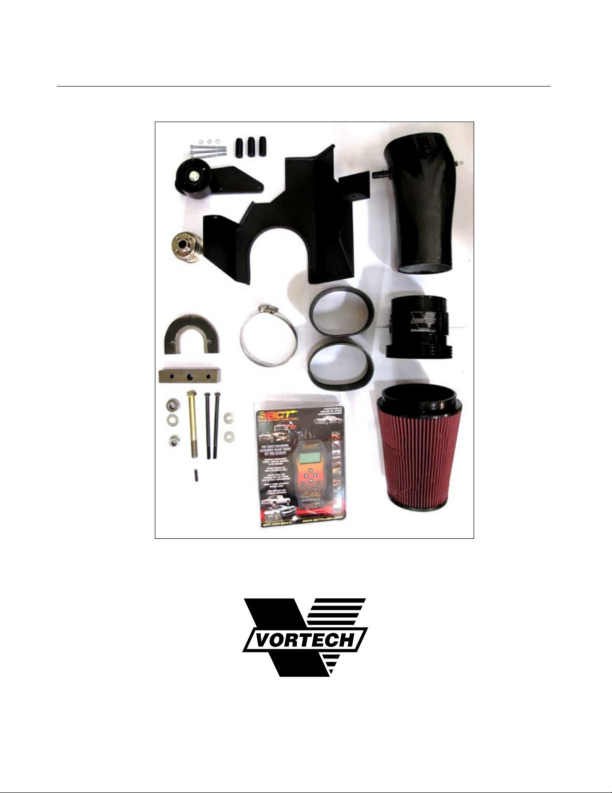
PARTS LIST
IMPORTANT: Before beginning installation, verify that all parts are included in the kit.
Report any shortages or damaged parts immediately.
PART NO. DESCRIPTION QTY
007125 POWER PACK INSTRUCTION MAN 1
2L031-265-02 PULLEY, GT500 2.65" OEM REPL 1
4LFR110-031 AUX IDLER ASSY, 07-09 GT500 1
2A017-753-03 SPACER, PILOT, .750 OD X 1.650 3
4FD017-011 PILOT, 6203/5 BRG, 1/2 SCREW 1
4LFR010-031 PLATE, AUX IDLER, GT500VTS 1
4LFR017-011 SPACER, ADJ IDLER, 07-09 GT500 1
4LFR116-011 IDLER ASSY, SMOOTH, 10-RIB, 3.50 1
7C012-065 M12 X 1.75 X 65MM HX 1
7C060-091 M6 X 1.0 X 90MM SHCS PLT GR12. 3
7G012-175 MACH NUT, COG DRV, SPECIAL 1
7J006-093 6MM WASHER, PLATED 3
4LFR212-020 CAI ACCESSORY KIT, GT500 1
4LFR010-020 HEAT SHIELD, AIR FILTER, GT500 1
4LFR112-020 INTAKE AIR TUBE ASSY, GT500 1
7PS500-300 SLEEVE, Ø5.0 X 3.0, 3-PLY, MAT 2
7R002-080 #80 SAE TYPE F SS HOSE CLAMP 4
7U030-046 5/32" VACUUM LINE 2
8A003-111 MAF HSG, 07-10 GT500, 123MM 1
8H040-600 AIR FILTER, 6" FLANGE X 9" LONG 1
5A003-062 SCT TUNER, GT500 UPGRADE KIT 1
TL0336 TOOL SET, GT500 OEM PULLEY 1
7A375-651 3/8-16 X 6-1/2 HX GR8 2
7C080-031 M8 X 1.25 X 30MM SET SCREW 1
7F625-001 5/8"-18, NYLOC-NUT 1
7J375-044 3/8 SAE WASHER, PLTD 2
7J625-001 5/8", SAE, FLAT WASHER 1
7T001-001 1/2" STEEL PULLER 1
7T001-002 1.250" SOLID SQUARE SUPPORT BL 1
7T625-001 5/8" THRUST BEARING 1
7T625-002 MODIFIED 5/8-18 SCREW EXT THD, 1
© 2010 Vortech Engineering, LLC
iv
All Rights Reserved, Intl. Copr. Secured.
27AUG2010 GT500 OEM POWER PACK
DP/N: 007125v1.0
Page 6
1. OEM SUPERCHARGER PULLEY REMOVAL
NOTE: It is best to attempt to remove the pulley only
after the vehicle has been allowed to cool down,
preferably overnight. It is also much easier to
remove the pulley in the morning when all the
metals are still cold.
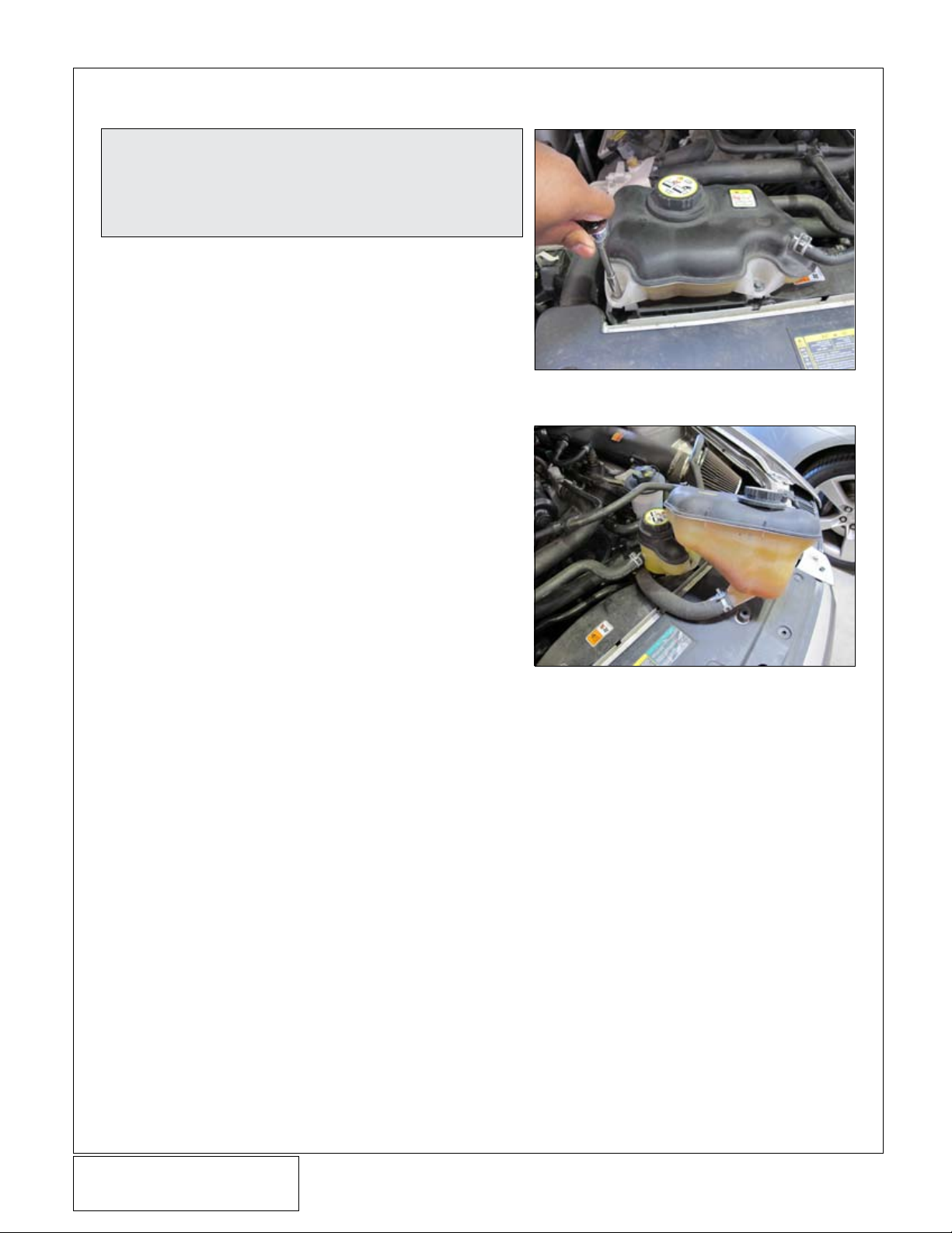
A. Disconnect the negative battery cable.
B. Remove the two screws securing the de-gas bot-
tle to the vehicle with a 10mm socket (See Figure
1-a)
C. Temporarily relocate the de-gas bottle as shown
to gain access to the serpentine belt tensioner
and supercharger pulley. (See Figure 1-b)
Fig. 1-a
Fig. 1-b
DP/N: 007125v1.0
© 2010 Vortech Engineering, LLC
All Rights Reserved, Intl. Copr. Secured.
27AUG2010 GT500 OEM POWER PACK
1
Page 7
1. OEM SUPERCHARGER PULLEY REMOVAL, CONT’D
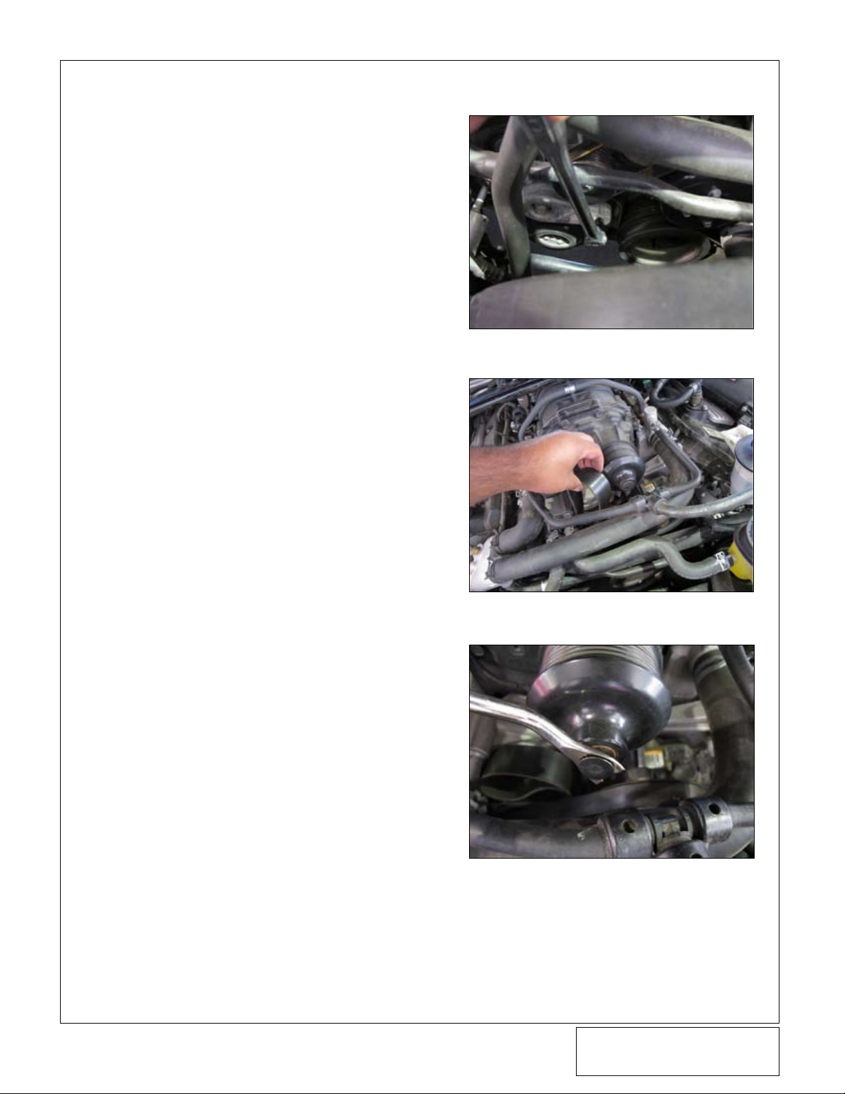
D. Using a 3/8” drive breaker bar on the tensioner,
remove the serpentine belt from the supercharger
pulley. (See Figure 1-c & 1-d)
E. The center plug on the supercharger will need to
be removed so as not to damage it when removing or installing the pulley. Using a flat screw driver
or upholstery tool, pry the plug off the supercharger snout. (See Figure 1-e)
Fig. 1-c
Fig. 1-d
Fig. 1-e
© 2010 Vortech Engineering, LLC
2
All Rights Reserved, Intl. Copr. Secured.
27AUG2010 GT500 OEM POWER PACK
DP/N: 007125v1.0
Page 8
1. OEM SUPERCHARGER PULLEY REMOVAL, CONT’D
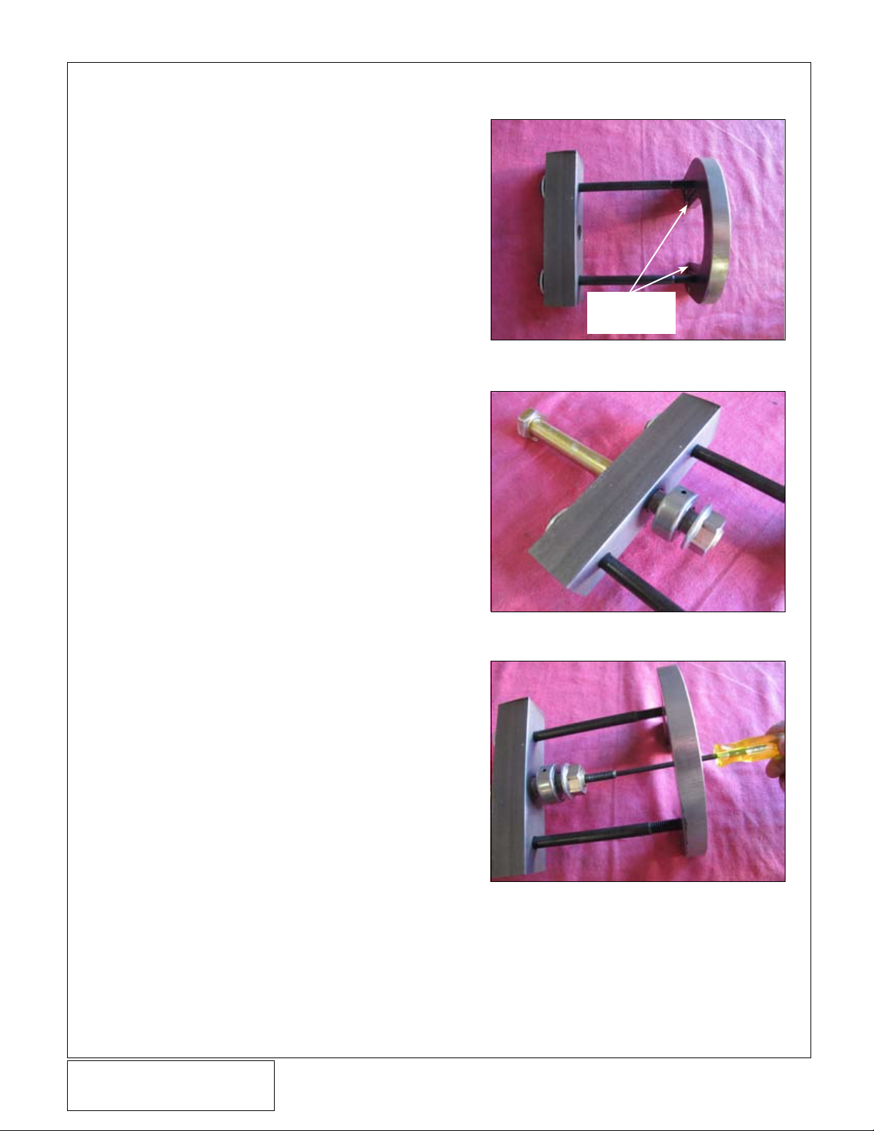
F. Pre-assemble the supplied tool as shown. Insert
the two 3/8”x6-1/2" screws with washers through
the outer holes of the pulley removal bar and
thread them evenly into the pulley removal plate.
Be sure the two 3/8” bolts are exactly flush to the
back of the pulley removal plate. It is very important that the pulley removal plate and the pulley
removal bar are evenly spaced. (See Figure 1-f)
G. At this time you will need to lightly apply anti-sieze
or moly grease to the threads of the 5/8” screw
and light oil into the thrust bearing. Then insert the
screw through the center hole of the pulley removal bar.
H. Assemble the thrust bearing with the free rolling
face towards the pulley removal bar, and install
the supplied 5/8” nut with the flange surface
towards the back of the thrust bearing. (See
Figure 1-g)
I. Apply loctite onto the supplied M8 set screw and
thread it into the center of the 5/8” screw. Tighten
the set screw. This will aid in keeping the tool centered on the supercharger pulley shaft. (See
Figure 1-h)
Step in plate must
face as shown
Fig. 1-f
Fig. 1-g
Fig. 1-h
DP/N: 007125v1.0
© 2010 Vortech Engineering, LLC
All Rights Reserved, Intl. Copr. Secured.
27AUG2010 GT500 OEM POWER PACK
3
Page 9

1. OEM SUPERCHARGER PULLEY REMOVAL, CONT’D
J. Install the tool assembly onto the supercharger
pulley, with the back side of the OE pulley nested
into the step in the removal plate. (See Figure 1-i)
NOTE: Instead of an open end wrench, we recommend
installing a boxed end wrench on the flanged nut
to apply the torque more evenly and ensure the
wrench will not round the nut corners. Slide the
box wrench over the nut.
K. Rotate the 5/8" screw clockwise so that the M8
set screw will thread into the end of the supercharger shaft. Snug (do not tighten) the screw into
the supercharger shaft.
L. Using either a 15/16” socket on a breaker bar or a
boxed wrench, hold the end of the 5/8” screw from
turning while using the other wrench to turn the
flanged nut to pull the pulley off.
NOTE: Removing the OEM pulley only after the engine
has been allowed to cool overnight will allow the
pulley to effectively “break loose” from the shaft
and produce a “POP” sound when it becomes
free.
Fig. 1-i
M. Listen for the “POP” to alert you that the pulley
has broken free, it will become easier to turn the
nut at this point and you should see the pulley
coming off. (See Figure 1-j)
Fig. 1-j
© 2010 Vortech Engineering, LLC
4
All Rights Reserved, Intl. Copr. Secured.
27AUG2010 GT500 OEM POWER PACK
DP/N: 007125v1.0
Page 10

2. NEW SUPERCHARGER PULLEY INSTALLATION
A. Once the OEM pulley has been removed, remove
the tool from the pulley and shaft. Reconfigure the
tool as shown to install the new pulley. Ensure
that the free rolling face of the thrust bearing is
facing the flanged nut, and not the pulley and
washer. (See Figure 2-a)
B. If needed, apply more lubricant to the threads of
the 5/8” screw and the bearing.
C. Insert the tool through the new pulley as shown
D. Thread the install tool into the center threaded
hole of the supercharger until the 5/8” screw seats
against the supercharger shaft. (See Figure 2-b &
2-c)
Fig. 2-a
Fig. 2-b
Fig. 2-c (pulley shown installed for clarity)
DP/N: 007125v1.0
© 2010 Vortech Engineering, LLC
All Rights Reserved, Intl. Copr. Secured.
27AUG2010 GT500 OEM POWER PACK
5
Page 11

2. NEW SUPERCHARGER PULLEY INSTALLATION, CONT’D
E. Using the 15/16” wrenches/sockets, slowly drive
the new pulley onto the supercharger until the
washer seats the new pulley flush to the supercharger pulley shaft. You will know it is flush when
the new pulley will not go in any further. (See
Figure 2-d)
F. Verify the new pulley is flush to the supercharger
pulley shaft as shown. (See Figure 2-e)
G. Re-insert the plastic cap into the supercharger
pulley shaft.
Fig. 2-d
Fig. 2-e
© 2010 Vortech Engineering, LLC
6
All Rights Reserved, Intl. Copr. Secured.
27AUG2010 GT500 OEM POWER PACK
DP/N: 007125v1.0
Page 12

3. AUXILIARY IDLER PULLEY INSTALLATION
A. Remove the three screws securing the OEM
Charge Air Cooler (CAC) water manifold to the
lower manifold using an 8mm socket (See Figure
3-a)
B. Assemble the supplied Auxiliary Idler Pulley in the
sequence as follows:
1: Install the pilot spacer onto the M12 screw
with the smaller diameter facing away from the
head of the screw as shown (See Figure 3-b)
2: Insert the M12 bolt with pilot spacer through
the idler. Ensure that the snap ring inside the idler
is facing away from the head of the screw. (See
Figure 3-c)
3: Insert the idler spacer with the conical face
into the idler assembly (See Figure 3-c)
4: Insert the custom machined nut into the slot
in the bracket from the counter-bored hole side,
then thread the idler assembly from the opposite
side into the machined nut. DO NOT TIGHTEN
IDLER PULLEY AT THIS TIME. (See Figure 3-d)
5: Install the 1.65” long spacers into the coun-
ter-bored holes on the bracket. (See Figure 3-d)
6: Insert the three M6 screws with washers
through the bracket, from the idler assembly side.
Fig. 3-a
Fig. 3-d
Fig. 3-b
Fig. 3-c
DP/N: 007125v1.0
© 2010 Vortech Engineering, LLC
All Rights Reserved, Intl. Copr. Secured.
27AUG2010 GT500 OEM POWER PACK
7
Page 13

3. AUXILIARY IDLER PULLEY INSTALLATION, CONT'D
C. Lower idler assembly below the supercharger
snout and mount onto the previously removed
water manifold screws. Use a 5mm Allen key to
tighten the screws. (See Figure 3-e & 3-f)
D. Have an assistant pry the belt tensioner to install
the belt. While the assistant holds the tensioner,
adjust the idler pulley so that the belt runs parallel
with in ¼” of itself under the supercharger pulley.
Tighten the M12 bolt using a 19mm Socket. (See
Figure 3-g)
Fig. 3-e
Fig. 3-f
Fig. 3-g
© 2010 Vortech Engineering, LLC
8
All Rights Reserved, Intl. Copr. Secured.
27AUG2010 GT500 OEM POWER PACK
DP/N: 007125v1.0
Page 14

4. OEM AIR BOX/AFTERMARKET CAI REMOVAL
A. Remove the four nuts securing the factory
installed strut tower brace using a 13mm socket.
(See Figure 4-a) Remove the factory strut brace
as it will not be reinstalled since it would interfere
with the Power Pack CAI Kit. Re-install the four
nuts and tighten.
B. Using a 5/16” nut driver, loosen the hose clamp at
the throttle body and air box or filter assembly.
(See Figure 4-b & 4-c)
Fig. 4-a
Fig. 4-b
Fig. 4-c
DP/N: 007125v1.0
© 2010 Vortech Engineering, LLC
All Rights Reserved, Intl. Copr. Secured.
27AUG2010 GT500 OEM POWER PACK
9
Page 15

4. OEM AIR BOX/AFTERMARKET CAI REMOVAL, CONT'D
C. Disconnect the MAF sensor harness wiring from
the MAF sensor. Pull the red retainer away from
the MAF to unlock the connector, then squeeze
and pull to remove the connector. (See Figure
4-d)
D. Remove the breather hose connection from the
intake tube (See Figure 4-e)
E. Remove the Bypass Valve vacuum hose (See
Figure 4-f)
Fig. 4-d
Fig. 4-e
Fig. 4-f
10
© 2010 Vortech Engineering, LLC
DP/N: 007125v1.0
All Rights Reserved, Intl. Copr. Secured.
27AUG2010 GT500 OEM POWER PACK
Page 16

4. OEM AIR BOX/AFTERMARKET CAI REMOVAL, CONT'D
F. Using a 10mm socket, temporarily remove the
screw securing the ABS brake module and set
aside. This screw will be reused to secure the
Power Pack CAI Heat Shield in a later step. (See
Figure 4-g)
G. Using a 10mm socket, remove the screws secur-
ing the factory air box to the inner fender well. Pull
entire assembly out. (See Figure 4-h)
Fig. 4-g
Fig. 4-h
DP/N: 007125v1.0
© 2010 Vortech Engineering, LLC
All Rights Reserved, Intl. Copr. Secured.
27AUG2010 GT500 OEM POWER PACK
11
Page 17

5. POWER PACK CAI INSTALLATION
A. Locate the supplied vacuum hose. Using a utility
knife, cut a slit on one side of the hose the entire
length. A box cutter works best when the blade is
only exposed to cut half the hose diameter. Using
a vise to hold the utility knife in place, while running the hose over it in short lengths works best.
Use the hose parting line to ensure you cut a
straight line.
B. Attach the vacuum hose to the heat shield as
shown. (See Figure 5-a) Trim the excess hose off.
C. Use the remainder hose to attach to the lower
portion of the heat shield as shown. (See Figure
5-e) This will ensure the heat shield does not rub
through the A/C lines below where it will be positioned. (See Figure 5-b)
D. Install the heat shield as shown and secure it with
the hardware from the OEM air box and the hardware used to secure the ABS bracket from a previous step. (See Figure 5-c)
Fig. 5-a
Fig. 5-b
Fig. 5-c
12
© 2010 Vortech Engineering, LLC
DP/N: 007125v1.0
All Rights Reserved, Intl. Copr. Secured.
27AUG2010 GT500 OEM POWER PACK
Page 18

5. POWER PACK CAI INSTALLATION, CONT'D
E. Remove the MAF sensor module from the intake
tube assembly using a 2.5mm allen key. (See
Figure 5-d) Inspect the o-ring for damage or
deformation, replace if necessary.
F. Locate the new MAF sensor housing from the kit
and install the MAF sensor module into the housing, securing it with the factory hardware. (See
Figure 5-e)
G. Install the cone air filter onto the MAF housing.
H. Place filter and MAF housing assembly in the heat
shield area. Be sure the MAF sensor module is
positioned outside the heat shield. (See Figure
5-f)
Fig. 5-d
Fig. 5-e
Fig. 5-f
DP/N: 007125v1.0
© 2010 Vortech Engineering, LLC
All Rights Reserved, Intl. Copr. Secured.
27AUG2010 GT500 OEM POWER PACK
13
Page 19

5. POWER PACK CAI INSTALLATION, CONT'D
NOTE: Using a light coat of clean engine oil will help
the couplers slide over the beads.
I. Assemble the carbon fiber intake tube with the
supplied hose couplers. Lubricate the inside of the
coupler on the filter side to aid in sliding over from
the intake tube and onto the MAF housing. This
coupler will need to be installed all the way onto
the carbon fiber intake tube until it is flush. (See
Figure 5-h)
K. Slide the intake tube coupler onto the throttle
body until it seats and tighten both hose clamps.
(See Figure 5-g)
L. With both clamps loose on the filter side, support
the filter with one hand and slide the coupler from
the intake tube over onto the MAF housing.
Re-aligning the housing and intake tube as you
slide the coupler will assist in engaging the coupler to the housing. (See Figure 5-i).
M. Once the entire intake tube assembly is posi-
tioned properly (ensure the MAF is positioned outside heat shield as shown) and with adequate
clearance, then tighten all the hose clamps. (See
Figure 5-j)
N. Connect the MAF wiring harness.
O. Re-attach the breather hose.
P. Re-connect the bypass valve vacuum hose.
Fig. 5-g
Fig. 5-j
Fig. 5-h
Fig. 5-i
14
© 2010 Vortech Engineering, LLC
DP/N: 007125v1.0
All Rights Reserved, Intl. Copr. Secured.
27AUG2010 GT500 OEM POWER PACK
Page 20

6. REFLASH COMPUTER
IMPORTANT! To ensure trouble-free programming of your vehicle's computer:
• Make sure the vehicle's battery is sufficiently charged.
• Turn off all accessories and close doors to prevent unnecessary drain on the battery.
• Do not attempt to program your vehicle while a battery charger is connected.
• Improper battery voltage will result in failure of the programming process.
• Do not disconnect the cable or turn off the ignition during programming.
NOTE: • All vehicles equipped that have aftermarket ste-
ARROW KEYS
reos will experience problems with the ability to
re-program the vehicle’s ECM. It is necessary to
disconnect the aftermarket stereo from the factory wiring harness before continuing with the programming procedure.
CANCEL
SELECT
Fig. 6-a
A. Reconnect the battery if previously dis-
connected.
B. Locate the vehicle’s OBD2 connector
located under the dash on the driver side
of the vehicle. (See Fig 6-b)
C. Attach the OBD2 connector from the
reflash tool that is provided in the kit to
the vehicle’s OBD2 port. Make sure this
connector is seated all the way in the
vehicle’s OBD2 port. Do not allow this
connector to become disconnected during programming or damage may occur
to the vehicle’s ECM. (See Fig 6-c)
• Do not disturb the cable or turn the ignition off
during this time. If the programming is disrupted,
the computer will not start or run your vehicle!
OBD-II
CONNECTOR
Fig 6-b
DP/N: 007125v1.0
© 2010 Vortech Engineering, LLC
All Rights Reserved, Intl. Copr. Secured.
27AUG2010 GT500 OEM POWER PACK
Fig 6-c
15
Page 21

6. REFLASH COMPUTER, CONT'D
NOTE: If you have any questions throughout this proce-
dure, please contact our service department for
further assistance.
D. The reflash tool should power up and display
PROGRAM VEHICLE at the top of the screen.
Press the SELECT button. (See Fig 6-d)
E. PREPROGRAMED TUNE will be displayed at
the top of the screen. Press the SELECT button. (See Fig 6-e)
F. Read the disclaimer entirely, then press the
SELECT button if you agree with the terms of
the disclaimer. (See Fig 6-f)
G. At this point you will need to turn the ignition to
the ON position (do not start the vehicle). Set
the parking brake and press the SELECT button to continue. (See Fig 6-g)
Fig 6-d
Fig 6-e
Fig 6-f
Fig 6-g
16
© 2010 Vortech Engineering, LLC
DP/N: 007125v1.0
All Rights Reserved, Intl. Copr. Secured.
27AUG2010 GT500 OEM POWER PACK
Page 22

6. REFLASH COMPUTER, CONT'D
H. The reflash tool will proceed to check the
Operating System (OS) part number of the
vehicles ECU. (See Fig 6-h)
I. PROGRAM VEHICLE will be displayed at the
top of the screen. At this time make sure you
have turned off any additional accessories that
may cause unnecessary draw on the vehicles
battery (headlights, radio, etc.). Press the
SELECT button to proceed with BEGIN
PROGRAM. (See Fig 6-j)
Fig 6-h
NOTE: Once the programming sequence has been start-
ed use care NOT to disturb the cable, or turn the
ignition or any accessories on or off during this
time. Throughout the programming sequence it is
normal for the Reflash tool to AUTOMATICALLY
cycle the vehicles power on and off. If the programming is disrupted, permanent damage to the
vehicles computer may result!
Fig 6-i
Fig 6-j
DP/N: 007125v1.0
© 2010 Vortech Engineering, LLC
All Rights Reserved, Intl. Copr. Secured.
27AUG2010 GT500 OEM POWER PACK
Fig 6-k
17
Page 23

6. REFLASH COMPUTER, CONT'D
L. The reflash tool will then automatically proceed
through the following screens during the pro-
gramming process. (See Fig 6-k thru 6-p)
i. Unlock ECU
ii. Upload ECU
iii. Setup Device
iv. Make Adjustments
v. Calculate Checksums
vi. Unlock ECU
vii. Download tune
Fig 6-l
Fig 6-m
Fig 6-n
Fig 6-o
Fig 6-p
18
© 2010 Vortech Engineering, LLC
DP/N: 007125v1.0
All Rights Reserved, Intl. Copr. Secured.
27AUG2010 GT500 OEM POWER PACK
Page 24

6. REFLASH COMPUTER, CONT'D
M. Once the reflash tool has completed the
DOWNLOAD TUNE process the screen should
read "Turn Key Off And Remove key." At this
time remove the key and press the SELECT
button to continue. (See Fig 6-q)
N. Once the tool has successfully completed the
POWER DOWN ECU sequence you will see
"Download Complete" displayed on the screen.
Press the SELECT BUTTON. (See Fig 6-r,
6-s)
O. CONGRATULATIONS! You have successfully
completed reflashing the vehicle's ECU with
the Vortech Supercharger Calibration. You may
now unplug the reflash tool from the vehicle's
OBD2 port.
Fig 6-q
Fig 6-r
Fig 6-s
DP/N: 007125v1.0
© 2010 Vortech Engineering, LLC
All Rights Reserved, Intl. Copr. Secured.
27AUG2010 GT500 OEM POWER PACK
19
Page 25

7. FINAL CHECK
WARNING: Do not attempt to operate the vehicle
until ALL components are installed and ALL
operations are completed including the final
check.
A. Reinstall the de-gas bottle and tighten screws.
B. Confirm that all fasteners are properly secured
and tight.
C. Make sure all wires and hoses are routed away
from hot, moving or sharp objects.
D. Test drive the vehicle.
E. Custom calibration will be REQUIRED if the drive
speeds of the supercharger and the boost levels
are changed from the supplied components.
Always listen carefully for engine detonation.
Discontinue heavy throttle usage if detonation is
heard.
20
© 2010 Vortech Engineering, LLC
DP/N: 007125v1.0
All Rights Reserved, Intl. Copr. Secured.
27AUG2010 GT500 OEM POWER PACK
Page 26

®
ENGINEERING, LLC
1650 Pacific Avenue, Channel Islands, CA 93033-9901 • Phone 805 247-0226
Fax: 805 247-0669 • www.vortechsuperchargers.com • M-F 8:00 AM - 4:30 PM (PST)
 Loading...