

Page 1

DP/N: 4NT020-010 - v1.1 06/09/07
1650 Pacific Avenue, Channel Islands CA 93033-9901 • Phone: 805 247-0226
Fax: 805 247-0669 • www.vortechsuperchargers.com • M-F 8:00AM - 4:30PM (PST)
ENGINEERING, LLC
2004-2006
Nissan Titan
Supercharger System
Installation Instructions
50 State Smog Legal Per CARB EO #D-213-25
®
Page 2

P/N: 4NT020-010
©2007 Vortech Engineering, LLC
All Rights Reserved, Intl. Copr.Secured
09JUN07 v1.1 NissanTitan(4NTv1.1)
ii
FOREWORD
Take note of the following before proceeding:
1. Proper installation of this supercharger kit requires general automotive
mechanic knowledge and experience.Please browse through each step of
this instruction manual prior to beginning the installation to determine if you
should refer the job to a professional installer/technician.Please contact
your dealer or Vortech Engineering for possible installers in your area.
2. This product was designed for use on stock (un-modified, OEM) vehicles. The
PCM (computer), engine, transmission, drive axle ratios and tire O.D. must be stock. If
the vehicle or engine has been modified in any way, check with Vortech prior to installation and use of this product.
3. Use only premium grade fuel with a minimum of 91 octane (R+M/2).
4. Always listen for any sign of detonatlion (knocking/pinging) and discontinue hard use
(no boost) until problem is resolved.
5. Vortech is not responsible for any clutch, transmission, drive-line or engine damage.
Exclusions from Vortech warranty coverage considerations include,
but not limited to:
1. Neglect, abuse, lack of maintenance, abnormal operation or improper installation.
2. Continued operation with an impaired vehicle or sub-system.
3. The combined use of Vortech components with other modifications such as, but not limit-
ed to, exhaust headers, aftermarket camshafts, nitrous oxide, third party PCM programming or other such changes.
©2007 VORTECH ENGINEERING, LLC
All rights reserved. No part of this publication may be reproduced, transmitted, transcribed, or translated
into another language in any form, by any means without written permission of Vortech Engineering, LLC.
T
his manual provides information on the installation, maintenance and service of the
Vortech supercharger kit expressly designed for this vehicle.All information, illustra-
tions and specifications contained herein are based on the latest product information
available at the time of this publication.Changes to the manual may be made at any time
without notice. Contact Vortech Engineering for any additional information regarding this kit
and any of these modifications at (805) 247-0228 8:00am-4:30pm PST.
IMPORTANT NOTE
OEM exhaust catalytic converter life may be dramatically
reduced when the vehicle is subjected to frequent heavy
or full throttle operation.Vortech is not responsible for any
damage that may occur to these emission control devices.
STOP
Page 3

P/N: 4NT020-010
©2007 Vor tech Engineer ing, LLC
All Rights Reserved, Intl. Copr.Secured
09JUN07 v1.1 NissanTitan(4NTv1.1)
iii
TABLE OF CONTENTS
FOREWORD . . . . . . . . . . . . . . . . . . . . . . . . . . . . . . . . . . . . . . . . . . . . . . . . . . . . . . . .ii
TABLE OF CONTENTS . . . . . . . . . . . . . . . . . . . . . . . . . . . . . . . . . . . . . . . . . . . . . . . .iii
IMPORTANT NOTES . . . . . . . . . . . . . . . . . . . . . . . . . . . . . . . . . . . . . . . . . . . . . . . . . .iv
TOOL & SUPPY REQUIREMENTS . . . . . . . . . . . . . . . . . . . . . . . . . . . . . . . . . . . . . . .v
PARTS LIST (2004-2006 Nissan Titan) . . . . . . . . . . . . . . . . . . . . . . . . . . . . . . . . . . . .vi
1. PREPARATION/REMOVAL . . . . . . . . . . . . . . . . . . . . . . . . . . . . . . . . . . . . . . . . .1
2. FUEL INJECTION REPLACEMENT . . . . . . . . . . . . . . . . . . . . . . . . . . . . . . . . . .2
3. MOUNTING BRACKET/SUPERCHARGER INSTALLATION . . . . . . . . . . . . . . . .3
4. OIL FEED INSTALLATION . . . . . . . . . . . . . . . . . . . . . . . . . . . . . . . . . . . . . . . . .5
5. INLET DUCT INSTALLATION . . . . . . . . . . . . . . . . . . . . . . . . . . . . . . . . . . . . . . .6
6. COOLANT LINE MODIFICATION . . . . . . . . . . . . . . . . . . . . . . . . . . . . . . . . . . . .7
7. CHARGE AIR COOLER (CAC) ASSEMBLY INSTALLATION . . . . . . . . . . . . . . . .8
8. PIGGYBACK ENGINE CONTROL UNIT (ECU) INSTALLATION . . . . . . . . . . . . .11
9. IN-TANK-FUEL PUMP INSTALLATION . . . . . . . . . . . . . . . . . . . . . . . . . . . . . . . .12
10. FINAL ASSEMBLY AND CHECK . . . . . . . . . . . . . . . . . . . . . . . . . . . . . . . . . . . .13
Page 4

P/N: 4NT020-010
©2007 Vor tech Engineer ing, LLC
All Rights Reserved, Intl. Copr.Secured
09JUN07 v1.1 NissanTitan(4NTv1.1)
iv
This product is protected by state common law, copyright and/or patent. All
legal rights therein are reserved.The design, layout, dimensions, geometry,
and engineering features shown in this product are the exclusive property of
Vortech Engineering, LLC.This product may not be copied or duplicated in
whole or part, abstractly or fundamentally, intentionally or for tuitously, nor shall
any design, dimension, or other information be incorporated into any product
or apparatus without prior written consent of Vortech Engineer ing, LLC.
NOTICE
2004-2006 Nissan Titan
Page 5
P/N: 4NT020-010
©2007 Vor tech Engineer ing, LLC
All Rights Reserved, Intl. Copr.Secured
09JUN07 v1.1 NissanTitan(4NTv1.1)
v
Before beginning this installation, please read through this entire instruction booklet and the Street
Supercharger System Owner’s Manual which includes the Limited Warranty Program, the Warranty
Registration form and return envelope.
Vortech supercharger systems are performance improving devices. In most cases, increases in
torque of 30-35% and horsepower between 35-45% can be expected with the boost levels specified
by Vortech Engineering.This product is intended for use on healthy, well maintained engines.
Installation on a worn-out or damaged engine is not recommended and may result in failure of the
engine as well as the supercharger.Vor tech Engineering is not responsible for engine damage.
Installation on new vehicles will not harm or adversely affect the break-in per iod so long as factory
break-in procedures are followed.
For best performance and continued durability, please take note of the following key points:
1. Use only premium grade fuel 91 octane or higher (R+M/2).
2. The engine must have stock compression ratio.
3. If the engine has been modified in any way, check with Vor tech prior to using this product.
4. Always listen for any sign of detonation (pinging) and discontinue hard use (no boost) until the
problem is resolved.
5. Perfor m an oil and filter change upon completion of this installation and pr ior to test driving
your vehicle.Thereafter, always use a high grade SF rated engine oil or a high quality synthetic, and change the oil and filter at least every 3,000 miles. Never attempt to extend the oil
change interval beyond 3,000 miles, regardless of oil manufacturer’s claims as potential damage to the supercharger may result.
6. Before beginning installation, replace all spark plugs that are older than 1-year or 15,000
miles with original heat range plugs as specified by the manufacturer and reset timing to factory specifications (follow the procedures indicated within the factory repair manual and/or as
indicated on the factory underhood emissions tag). Do not use platinum spark plugs unless
they are original equipment. Change spark plugs every 20,000 miles.
TOOL & SUPPLY REQUIREMENTS
• Factory repair manual
• 3/8" socket and drive set:SAE & metric
• 3/8" Ratchet Extension 6"
• 1/2" socket and drive set:SAE & metric
• 3/8"NPT tap, 3/8-18 tap & handle
• Adjustable wrench
• Open end wrenches: 3/8", 7/16", 1/2", 9/16"
• Center punch and a 5/8" tapered punch
• 6 quarts (or what is specified in your owner’s manual)
SF rated quality engine oil, oil filter and wrench
If it has been 15,000 miles or more since your vehicle’s last spark plug change, then you will also need:
• Spark plug socket
• NEW spark plugs
2004-2006 Nissan Titan
Installation Instructions
Congratulations on selecting the best performing and best backed automotive
supercharger available today... the VORTECH®supercharger!
®
ENGINEERING, LLC
Page 6

P/N: 4NT020-010
©2007 Vor tech Engineer ing, LLC
All Rights Reserved, Intl. Copr.Secured
09JUN07 v1.1 NissanTitan(4NTv1.1)
vi
2E228-410 V2SQ S/C SC-TRM, CW CRVD, TITAN 1
2A037-300 S/C PULLEY 3.00" 7-GROOVE 1
5A003-100 UNICHIP ECU, NISSAN TITAN 1
4NT111-034 MOUNTING BRACKET ASY 1
4FG017-031 SPACER, TITAN S/C 5
2A047-126 BELT, 7-RIB, 126.5" 1
4FD017-011 BEARING PILOT .218"L 1
4NT017-011 SPACER, IDLER 1
4NT010-034 MOUNTING BRACKET, TITAN 1
4FA016-170 8-RIB IDLER SMOOTH 1
4PCW016-171 IDLER PULLEY TRIMMED 1
7J012-092 12mm WASHER 2
7A375-126 3/8-16 x 1.25" HXHD 5
7J375-044 3/8" WASHER 5
7R003-012 ADEL CLAMP 1
7C012-050 M12-1.75 x 50mm HXHD PLTD 1
7C012-080 M12-1.75 x80mm HHCS 1
4FA016-171 DUST COVER (IDLER PULLEY) 2
4NT112-010 AIR INTAKE ASY 1
4FA012-012 INTAKE ELBOW, 90° w/o BOSSES 1
4NT012-020 DUCT, S/C INLET 120°, TITAN 1
4NT110-050 ASY, INLET BULKHEAD, TITAN 1
7E010-049 #10 x 3/4" STSMS 4
7P375-020 3/8"NPT x 5/8" BARB BRASS 1
7P625-004 5/8" PLASTIC TEE 1
7R002-052 #52 SAE TYPE “F” SS HOSE CLAMP 2
7R002-056 #56 HOSE CLAMP 8
7S350-200 Ø3.5" x2" SLEEVE 2
7S350-300 SLEEVE, 3-1/2" x 3", BLUE 1
7U035-001 3-1/2" FLEX HOSE 1'
7U033-000 5/8" PCV HOSE 0.58'
8A103-081 MAF, 3.3"ID, NISSAN TITAN 1
8H040-040 AIR FILTER 1
4NT130-026 OIL FEED ASY 1
7P125-004 90° x 1/8"NPT x -4 STEEL 2
7P125-034 1/8"NPT STREET FITTING 1
7U250-000-260 STNLS BRAID HOSE STRT 1
7P125-125 1/8"NPT - 1/8" BSP 1
4NT130-036 OIL DRAIN ASY 1
7P375-055 1/2" BARB x 3/8"NPT x 90° 1
7U030-036 1/2" OIL DRAIN HOSE 0.67'
7R001-008 #8 HOSE CLAMPS 2
4NT020-010 INSTRUCTION MANUAL 1
4NT101-001 FUEL SYSTEM ASY, TITAN
4CJ017-021 SPACER, .625" COIL 4
5W001-050 HARNESS, FUEL INJ. PLUG w/WIRES 8
7C080-030 M8-1.25 x 30 HXHD CL10.9 4
8F001-342 FUEL PUMP w/SCREEN, GSS 342 1
8F060-042 FUEL INJECTOR, 42LBS RAIL STYL 8
4NT214-020 WATER PIPE ASY 1
4NT014-010 WATER PIPE LOWER, TITAN 1
4NT114-020 ASY, WATER PIPE UPPER 1
7R002-020 #20 HOSE CLAMP 8
4GK014-010 EXTENSION TUBE 1
7C060-025 6mm x 25mm HXHD 1
7J006-093 6mm WASHER 1
PART NO. DESCRIPTION QTY PART NO. DESCRIPTION QTY.
4NT112-020 DISCHARGE ASY 1
4NT012-010 DISCHARGE TUBE 1
7R002-016 #16 HOSE CLAMP 4
7R002-044 #44 HOSE CLAMP 5
7R002-052 #52 HOSE CLAMP 2
7R002-056 #56 HOSE CLAMP 7
7S275-200 2.75" x 2" SLEEVE 1
7S275-300 2.75" x 3" SLEEVE 1
7S325-275 90° SILICONE SLEEVE 1
7U030-046 VACUUM HOSE 2
7U133-100 HOSE, ELBOW, 90°, 1"ID, MOLDED 1
8D001-001 STANDARD BYPASS 1
8N201-270 WELDED CORE ASY, TITAN 1
8N106-170 WATER COOLER ASY 1
4NT010-010 BRKT, SETRAB LOWER 1
4NT010-020 BRKT, SETRAB UPPER 1
7A250-075 1/4-20 x .75" SHCS 1
7A250-074 1/4-20 x .75" HHCS 3
7E010-049 #10 x 3/4" STSMS 1
7F250-021 1/4-20 NYLOCK NUT 4
7K250-001 1/4" WASHER 8
7P500-026 3/4" x 90° BRASS FITTING 2
8N006-010 SETRAB COOLER, SINGLE PASS 1
8N105-170 WATER RESERVOIR ASY 1
4NT010-030 BRKT, WATER RESERVOIR 1
7A250-150 1/4-20 x 1.5" HXHD 2
7F250-021 1/4-20 NYLOCK NUT 2
7J250-001 1/4" WASHER 4
7P500-026 3/4" x 90° BRASS FITTING 2
8N055-030 TRIANGLE RESERVOIR TANK 1
8N107-170 WATER PUMP ASY 1
5W001-005 WIRE LOOM 3
5W001-009 16-14GA MALE SLIDE 1
5W001-010 16-14GA FEMALE SLIDE INSULATED 1
5W001-011 16-14GA EYELET .25" HOLE 1
5W001-013 14-16, BUTT CONNECTOR 2
5W001-024 MINI ATC FUSE TAP 1
5W001-025 FEMALE SLIDE MINI 1
5W014-030 14GA STRD WIRE BLACK 9
7P500-026 3/4" x 90° BRASS FITTING 2
7P500-078 3/4" STRAIGHT BRASS FITTING 2
7R003-027 ADEL CLAMP 1
7R007-001 NYLON RATCHET CLAMPS 10
7U030-065 MOLDED 90° HOSE SHORT 1
7U038-000 Ø3/4" HOSE 12
7U100-044 TIE-WRAPS, 4" NYLON 8
7U100-055 TIE-WRAPS 8
8F001-402 PIERBURG WATER PUMP 1
8N055-050 SURGE TANK CAP 1
8N056-060 SURGE TANK 1
IMPORTANT: Before beginning installation, verify that all parts are included in the kit. Report any shortages or damaged parts
immediately.
2004-2006 Nissan Titan
Part No. 4NT218-010SQ
ENGINEERING, LLC
PARTS LIST
®
Page 7

P/N: 4NT020-010
©2007 Vor tech Engineer ing, LLC
All Rights Reserved, Intl. Copr.Secured
09JUN07 v1.1 NissanTitan(4NTv1.1)
1
A. Disconnect the Battery.
B. Remove the engine cover.
C. Remove the engine cover bracket located
above the throttle body. Remove the wir ing
harness bracket from above the driver’s side
valve cover.
D. Disconnect the two breather tubes r unning
from the intake manifold to the plastic intake
duct and remove the duct, air-box lid, filter
and air-box.
E. Remove the grill.
F. Locate and remove the two clamps securing
the A/C line to the driver’s side firewall. Install
the supplied adel clamp on the firewall.Flip
over to lower the A/C line.(Doing this lowers
the A/C line to clear supercharger componentry.) (See Fig. 1-b.)
G. Remove the factory serpentine belt
H. Drain the engine coolant from the vehicle.
I. Remove the lower radiator hose connecting
the bottom of the radiator to the hard radiator
tube mounted off the engine’s front cover.
J. Remove the radiator hose that connects the
top opening of the hard radiator tube to the
plastic thermostat housing on the engine.
Remove the hard radiator tube.
K. Remove the MAF sensor from the factory air
box lid and set aside for reinstallation in an
upcoming step.
L. Remove the factory idler from the driver’s
side of the engine.
1. PREPARATION/REMOVAL
Fig. 1-a
Fig. 1-b
Fig. 1-c
REMOVE THE
CLAMPS
NOTE: Beginning the supercharger installation with
less than 1/8" a tank will make changing the
fuel pump easier.
Page 8

P/N: 4NT020-010
©2007 Vor tech Engineer ing, LLC
All Rights Reserved, Intl. Copr.Secured
09JUN07 v1.1 NissanTitan(4NTv1.1)
2
2. FUEL INJECTOR REPLACEMENT
A. Relieve the fuel system pressure.
B. Disconnect the eight fuel injector plugs and
retaining clips from the injectors.
C. Install the factory injector retaining clips onto
the new injectors.
D. Remove the four screws that hold down the
fuel rail to the intake manifold.Lift up on the
rails evenly and remove all eight injectors
E. Using a small amount of clean motor oil,
lightly lubricate the O-rings on both ends of
the Vortech supplied fuel injectors.
F. Install the new injectors into the fuel rails with
the terminals facing outward.
G. Carefully lower the fuel rail/injector assembly
down onto the intake manifold. Check to see
that each injector has been seated properly
into the intake manifold.
H. Install the four supplied .45"L spacers
between the fuel rails and the intake manifold. Use the supplied bolts to secure.
I. Use supplied plug & play connectors to con-
nect the OEM plug to the supplied fuel injectors.
J. Attach the injector plugs to the injectors.
Page 9

P/N: 4NT020-010
©2007 Vor tech Engineer ing, LLC
All Rights Reserved, Intl. Copr.Secured
09JUN07 v1.1 NissanTitan(4NTv1.1)
3
3. MOUNTING BRACKET/SUPERCHARGER INSTALLATION
A. Locate the driver’s side cam cover. Remove
the eight 6mm screws and carefully pry the
cover from the cylinder head. (See Fig. 3-a.)
B. Clean any excess sealant from the mating
surface on the cam sprocket housing.
C. Install the supplied 3/8"NPT x 1/2" barb x 90°
fitting into the 3/8"NPT hole in the supplied
supercharger mounting plate.
D. Lay a thin bead of RTV silicone sealant along
the machined groove on the rear of the
mounting plate. Install the mounting plate
using the factory hardware within five minutes.
E. Tighten the screws to 10 ft/lbs.
F. Assemble the supplied M12 x 80mm screw,
washer, non-flanged idler, and spacer. Using
thread sealant, secure the assembly into the
12mm hole in the plate. (See Fig. 3-b.)
G. Connect the oil drain hose to the supercharg-
er and secure it with a #8 hose clamp.
H. Install the 90° x 1/8"NPT x –4 fitting into the
brass oil feed fitting in the supercharger. Use
oil on the threads, not teflon tape.
I. Guide the oil drain hose through the hole in
the mounting plate. Using the supplied 3/8-16
x 1" hardware and washers, secure the
supercharger to the mounting plate.
J. Install the idler into the center ear on the
supercharger gear case using the supplied
M12 x 50mm bolt, washer, dust cover and
spacer. (See Fig. 3-d.)
K. Connect the oil drain hose to the brass fitting
in the mounting plate and secure with the
supplied #8 hose clamp.
L. Route and install the belt. (See Fig. 3-e.)
Fig. 3-a
Fig. 3-b
NOTE: Belt installation will be tight. For easiest
installation have a second person release
tension from the tensioner and route the
belt last around the lowest Vortech
smooth idler.
Fig. 3-c
Fig. 3-d
TRIMMED SIDE OF 4PCW016-171 PULLEY
Page 10

P/N: 4NT020-010
©2007 Vor tech Engineer ing, LLC
All Rights Reserved, Intl. Copr.Secured
09JUN07 v1.1 NissanTitan(4NTv1.1)
4
3. MOUNTING BRACKET/SUPERCHARGER INSTALLATION, cont’d
Fig. 3-e | Belt Routing Diagram
SUPPLIED IDLER
WATER
PUMP
POWER
STEERING
S/C
PULLEY
SUPPLIED IDLER
ALT
TENSIONER
FAN
A/C
CRANK
PULLEY
Page 11

P/N: 4NT020-010
©2007 Vor tech Engineer ing, LLC
All Rights Reserved, Intl. Copr.Secured
09JUN07 v1.1 NissanTitan(4NTv1.1)
5
Fig. 4-b
Fig. 4-c
Fig. 4-a
A. Locate and remove the oil pressure sender
from the oil pan. (Located to the driver’s side
of the oil filter.)
B. In place of the oil pressure sender, install the
supplied 1/8"BSPT male to 1/8"NPT female
fitting.
C. Insert the supplied 1/8"NPT street fitting into the
1/8"NPT female section of the installed fitting.
D. Install the factory oil pressure sensor into the
end of the street fitting.This positions the
sensor so that it is pointing away from the
engine block. (See Figs. 4-a, 4-b.)
E. Install the 1/8"NPT x –4 x 90° fitting into the
open hole in the street fitting. Orient the fitting
so that it points upward.
F. Connect one end of the supplied steel braid-
ed oil feed hose to the –4 end that is pointing
upward and route it up to the open –4 fitting
on the supercharger.Tighten both ends of the
hose.
G. Using the supplied adel clamp and 8-32 hard-
ware, secure the oil feed hose to the mounting plate. (See Fig. 4-c.)
4. OIL FEED INSTALLATION
NOTE: Use only clean engine oil on the pipe
threads. Teflon tape or pipe sealant is
not recommended as it might loosen
and cause blockage of the small oil feed
orifice resulting in possible supercharger
failure
ADEL CLAMP
INSTALL IN PLACE
OF THE OIL PRESSURE
SENDER
1/8"NPT STREET FITTING
1/8"NPT FEMALE / 1/8"BSP MALE
7P125-125
FACTORY OIL
PRESSURE SENDER
VORTECH 1/8"NPT
x -4 x 90°
Page 12
P/N: 4NT020-010
©2007 Vor tech Engineer ing, LLC
All Rights Reserved, Intl. Copr.Secured
09JUN07 v1.1 NissanTitan(4NTv1.1)
6
Fig. 5-b
Fig. 5-c
Fig. 5-d
Fig. 5-a
A. Loosen the driver’s side plastic splash shield
above the front wheel.
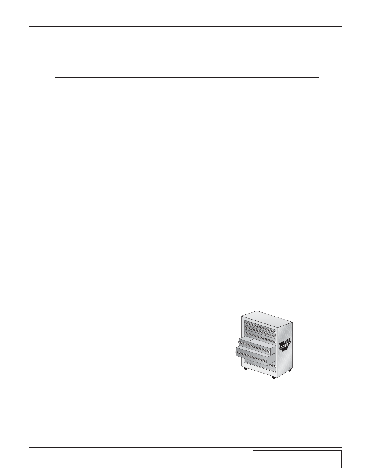
B. Attach the supplied air filter to the long leg of
the plastic 90° elbow. Attach a 2" long sleeve
to the open end of the elbow and secure with
a #56 hose clamp. (See Fig. 5-a.)
C. Insert the sleeved end through the air intake
hole from the inner fender. (This locates the
air filter above the driver’s side wheel). Attach
the inlet bulkhead assembly to the open end
of the sleeve and secure with a clamp. (See
Fig. 5-b.)
D. Holding the bulkhead assembly flush against
the inner fender, mar k and drill four pilot
holes and secure with sheet metal screws.
E. Install the supplied 3/8"NPT x 5/8" barb fitting
into the 3-1/2" aluminum inlet elbow. Attach
the short end of the inlet elbow to the supercharger inlet using a Ø3-1/2" x 2" sleeve and
clamps.
F Insert the MAF sensor that was removed in
Step 1 into the supplied MAF housing and
secure with the factory screws.Attach the
MAF to the open end of the supercharger
inlet elbow using the 3" long sleeve and
clamps. (The arrow on the MAF housing indi-
cates direction of air flow and must be pointed towards the supercharger). Plug in the
MAF sensor.
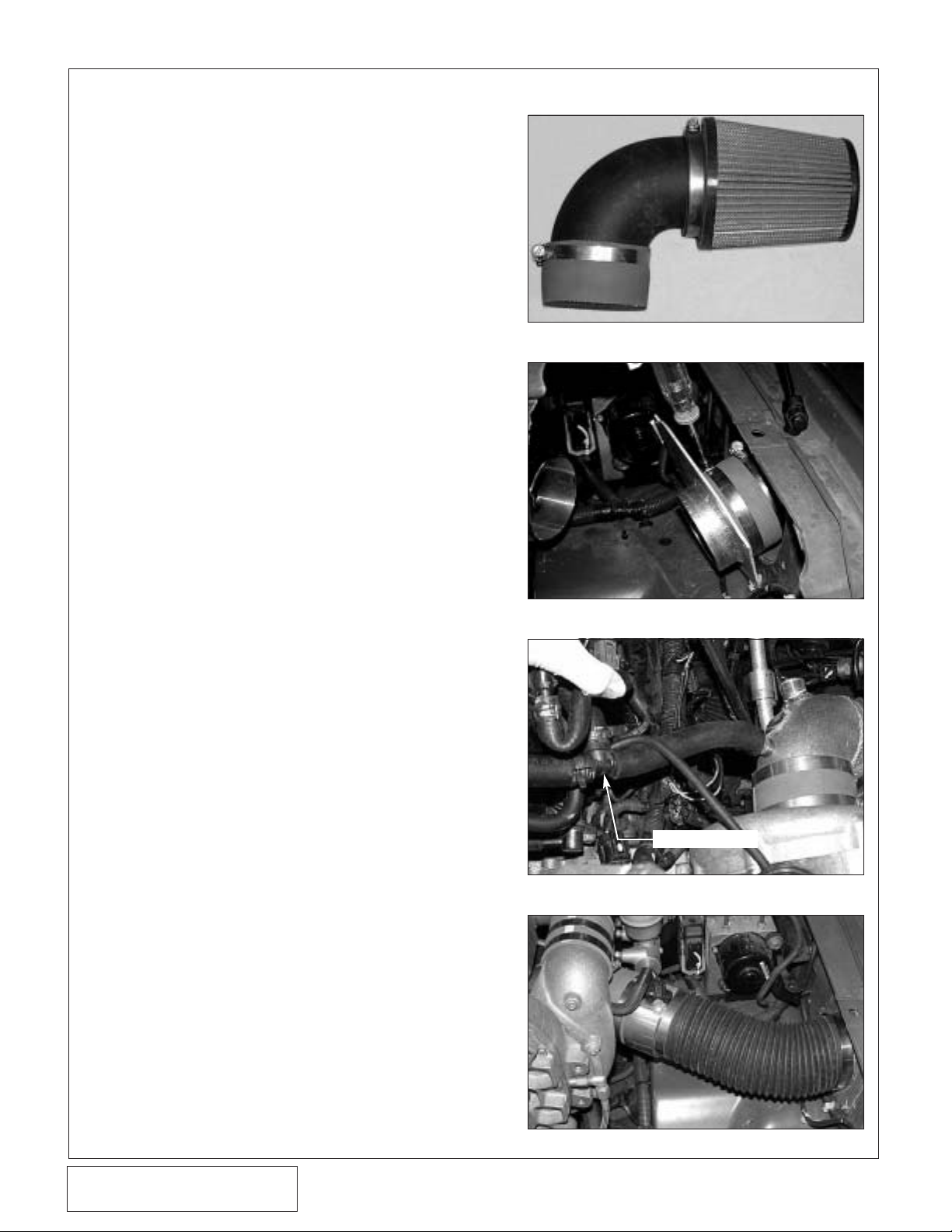
G. Locate the two factory breather tubes running
to the top of the intake manifold from each
valve cover. Using the supplied 5/8" TEE,
connect the two hoses. Connect the open
end of the TEE to the barbed fitting in the
inlet elbow with the supplied Ø5/8" hose.
(See Fig. 5-c.)
H. Attach the open end of the MAF to the inlet
bulkhead with flex-hose and secure with
clamps. (See Fig. 5-d.)
5. INLET DUCT INSTALLATION
SUPPLIED 5/8" TEE
Page 13
P/N: 4NT020-010
©2007 Vor tech Engineer ing, LLC
All Rights Reserved, Intl. Copr.Secured
09JUN07 v1.1 NissanTitan(4NTv1.1)
7
Fig. 6-d
6. COOLANT LINE MODIFICATION
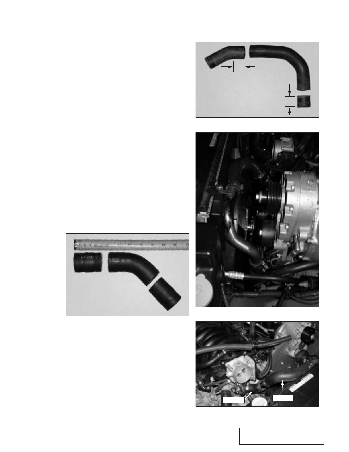
A. Locate the upper factory radiator hose
(Referenced as Hose “A”) that connected the
plastic thermostat housing to the hard radiator tube removed in Section 1.Using Fig. 6-a,
cut 2.5" sections from each end of the hose.
B. Locate the lower factory radiator hose
(Referenced as Hose “B”) that connected the
lower radiator port to the bottom of the hard
radiator tube. Use Fig. 6-b to cut the hose in
two places.
C. Connect the short end of the supplied long
L-shaped water tube to the bottom port on
the radiator with one of the previously
trimmed 2.5" pieces of hose and secure with
#20 hose clamps. (See Fig. 6-c.)
D. Remove the driver’s side fan shroud bolt and
secure the supplied water tube (with the
welded on bracket) using the supplied 6mm x
25mm HXHD and washer. (See Fig. 6-c.)
E. Using the center 90° section of Hose “A”,
hose extender, 90° section of Hose “B” and
#20 hose clamps, connect the thermostat
port to the open end of the installed upper
water tube. Make sure to keep the hose away
from the fan blades. (See Figs. 6-c, 6-d.)
F. Use the last 2.5" section of Hose “A” and two
#20 hose clamps to connect the two water
tubes together. (See Fig. 6-c.)
Fig. 6-a | Hose “A”
Fig. 6-b
Fig. 6-c
1"
1"
HOSE “A”
HOSE “B”
Page 14

P/N: 4NT020-010
©2007 Vor tech Engineer ing, LLC
All Rights Reserved, Intl. Copr.Secured
09JUN07 v1.1 NissanTitan(4NTv1.1)
8
A. DISCHARGE ASSEMBLY INSTALLATION:
1. Cut a 2" piece off the long end of the supplied Ø1.0" x 90° hose.
2. Attach the inlet of the bypass valve to the
bung on the charge cooler.
3. Trim the long leg of the supplied 90° hose
down to 5-1/2" long and attach to the discharge of the bypass valve. (See Fig. 7-a.)
4. Install the 1/2"NPT fittings into the charge
air cooler using thread sealant as shown.
(See Fig. 7-b.)
5. Use the Ø2.75" x 3" long sleeve to connect the inlet of the charge cooler to the
supercharger discharge.
6. Attach the 90° hose from the bypass
valve discharge to the bung on the supercharger inlet elbow. Tighten the #16 hose
clamps on all bypass valve connections.
7. Using the Ø2.75" x 2" long sleeve on the
discharge of the charge cooler, connect
the 90° discharge tube to the throttle body
with the Ø3.25" x Ø2.75" x 90° reducer
elbow.
8. Position the discharge assembly so that
there is no contact with brake lines, inlet
duct or the hood and tighten the hose
clamps. (See Fig. 7-c.)
B. SURGE T ANK INST ALLA TION:
1. Install a 3/4" barb x 90° fitting in the bottom of the supplied CAC surge tank.
Install a straight fitting in the topmost hole
of the plastic CAC surge tank. Using a 2"
length of Ø3/4" hose, connect the straight
fitting in the surge tank to the 90° fitting
installed into the top of the charge cooler.
2. Secure the surge tank to the bracket on
the charge cooler using 1/4-20 x 1/2" long
bolts.
C. CHARGE AIR COOLER RADIATOR
INSTALLATION:
1. Install two 1/2"NPT x 90° brass fittings
into the CAC radiator as shown. (See
Fig. 7-d.)
2. Using the supplied hardware, connect the
upper bracket to the driver’s side of the
CAC radiator.
3. Attach the lower bracket to the CAC radiator as shown.
7. CHARGE AIR COOLER (CAC) ASSEMBLY INSTALLATION
Fig. 7-a
Fig. 7-b
Fig. 7-c
NOTE: Make sure all CAC water hoses are routed
smoothly and have no kinks or sharp bends.
Page 15

P/N: 4NT020-010
©2007 Vor tech Engineer ing, LLC
All Rights Reserved, Intl. Copr.Secured
09JUN07 v1.1 NissanTitan(4NTv1.1)
9
Fig. 7-d
Fig. 7-e
Fig. 7-f
4. Locate the CAC radiator between the two
angled cross members, lining up the two
bottom bracket mounting locations. Bend
the horn bracket as necessary to provide
clearance. (See Fig. 7-d.)
5. Use a supplied sheet metal screw to
secure the upper bracket to the core support.
6. Connect a 48" piece of hose to the passenger’s side fitting on the CAC radiator.
Route the hose around the passenger’s
side of the radiator and up to the straight
fitting installed in the charge cooler.
D. RESERVOIR AND WATER PUMP
ASSEMBLY AND INSTALLATION:
1. Attach the water pump to the water reservoir using the supplied adel clamp in the
position shown. (See Fig. 7-e.)
2. Cut off the electrical plug on the water
pump leaving as much wire connected to
the pump as possible.Install the supplied
1/4" eyelet on the water pump ground
wire (brown wire). Install a male slide con-
nector onto the water pump positive wire
(green wire).
3. Using thread sealant, install a 1/2"NPT x
90° hose barb fitting into the top and bottom of the supplied plastic reservoir.
4. Connect the pump inlet to the bottom
reservoir fitting with the supplied 90°
hose.
5. Insert the water reservoir into the supplied bracket and insert into the area
behind the driver’s side front wheel next
to the frame rail.
6. Remove the two factory support screws
and re-install to secure the reservoir
bracket.
7. Use the supplied adel clamp and hardware to secure the water pump to the
trailing edge of the vehicle’s bumper.
(See Fig. 7-f.)
8. From the engine compartment, route the
supplied 3/4" hose from the bottom of the
surge tank to the top of the reservoir.
(See Fig. 7-h.)
9. Connect a hose running from the water
pump discharge to the 90° fitting installed
on the driver’s side of the CAC radiator.
7. CHARGE AIR COOLER (CAC) ASSEMBLY INSTALLATION, cont’d
FACTORY SCREWS
Page 16

P/N: 4NT020-010
©2007 Vor tech Engineer ing, LLC
All Rights Reserved, Intl. Copr.Secured
09JUN07 v1.1 NissanTitan(4NTv1.1)
10
Fig. 7-G
7. CHARGE AIR COOLER (CAC) ASSEMBLY INSTALLATION, cont’d
10. Connect the long black wire to the water
pump power wire using a female slide
connector.Route the water pump power
wire up to and across the cowl below the
windshield and secure with zip-ties.
11. Connect the supplied mini fuse tap to the
load side of the fuel pump fuse. Attach
the black wire to the fuse tap using the
supplied female connector. (See Fig.
7-g.)
12. Verify that all hose connections have
tightened clamps installed.
13. Remove the cap from the surge tank and
slowly fill the system with 25%/75%
coolant/water mix.
Fig. 7-h
CHARGE COOLER
SETRAB COOLER
FLOW
SUPPLIED
WATER
PUMP
Page 17

P/N: 4NT020-010
©2007 Vor tech Engineer ing, LLC
All Rights Reserved, Intl. Copr.Secured
09JUN07 v1.1 NissanTitan(4NTv1.1)
11
A. Install the supplied “piggyback ECU” per the
instructions supplied with the unit.
8. PIGGYBACK ENGINE CONTROL UNIT (ECU) INSTALLATION
Fig. 8-a
NOTE: There is no “accessory cable functionali-
ty” used with the supercharger kit and it
should be removed from the ECU if
equipped.
Page 18

P/N: 4NT020-010
©2007 Vor tech Engineer ing, LLC
All Rights Reserved, Intl. Copr.Secured
09JUN07 v1.1 NissanTitan(4NTv1.1)
12
Fig. 9-a
Fig. 9-b
9. IN-TANK-FUEL PUMP INSTALLATION
NOTE: Making sure that the vehicle has only a
small amount of fuel in the tank will make
the fuel tank easier to maneuver.
1. Disconnect the fuel lines (including the fuel
filler hose) and electrical connector(s) from
the fuel tank.
2. Remove the fuel tank from the vehicle.
Remove the fuel pump module from the tank
by rotating the clamp ring.
3. Remove the factory fuel pump. Install the supplied fuel pump in its place.
4. Re-assemble and install the fuel tank onto the
vehicle.
Page 19

P/N: 4NT020-010
©2007 Vor tech Engineer ing, LLC
All Rights Reserved, Intl. Copr.Secured
09JUN07 v1.1 NissanTitan(4NTv1.1)
13
10. FINAL ASSEMBLY AND CHECK
Fig. 10-a
A. If your vehicle has gone over 20,000 miles
since its last spark plug change, it is a good
idea to change the spark plugs now, before
test-driving.
B. Make sure that oil drain to oil pan fitting is
tight and that the engine is filled with factory
specified oil.
C. Make sure radiator and overflow tanks are
filled with a 50/50 coolant/water mix.
D. Make sure that the vehicle is filled with 91
octane or higher fuel before commencing a
test drive.
E. Turn the key ON and OFF several times to
build fuel pressure.Check for fuel leaks
(especially around the fuel injectors).
F. With the key on, make sure the charge air
cooler water pump is operating and that
water is flowing through the surge tank. Fill as
necessary. If water is not flowing, remove the
hose from the bottom of the surge tank and
lower until water flows out of hose.This
should prime the pump. Reconnect hose, verify water flow and top off surge tank. Do not
run the water pump for extended periods (30
seconds or more) without water flow.
G. Check all fittings, nuts, bolts and clamps for
tightness.
H. At this point it is OK to start the vehicle.
I. Turn off the vehicle and recheck all fluid lev-
els and verify that no hoses, wires, etc.are
near exhaust headers or moving parts and
that there is no fluid leakage.
J. Test drive the vehicle by gradually working up
to full throttle and paying close attention to
any abnormal sounds or engine detonation.
K. Read the STREET SUPERCHARGER SYS-
TEM OWNER’S MANUAL AND RETURN
THE WARRANTY REGISTRATION FORM
within thirty (30) days of purchasing your
supercharger system to qualify for the 3-year
limited warranty.
WARNING: Never operate your engine at full
throttle when the engine is cold.
Always allow plenty of time for the
oil to reach full operating temperature before running above 2,500
RPM. Full supercharger operating
temperature is generally achieved
only after the engine water temperature has been at the normal indicated operating range for two or
three minutes.
WARNING: Do not attempt to operate the
vehicle until ALL components are
installed and ALL operations are
completed including final check.
Failure to do so may cause PREMATURE FAILURE OF MAJOR
COMPONENTS.
WARNING: OEM exhaust catalytic converter
life may be dramatically reduced
when the vehicle is subjected to
frequent heavy or full throttle
operation. Vortech is not responsible for any damage that may
occur to these emission control
devices.
Page 20

DP/N: 4NT020-010 - v1.1 06/09/07
®
1650 Pacific Avenue, Channel Islands CA 93033-9901 • Phone: 805 247-0226
Fax: 805 247-0669 • www.vortechsuperchargers.com • M-F 8:00AM - 4:30PM (PST)
ENGINEERING, LLC
 Loading...