

Page 1
DP/N: 4GJ020-010 v1.0 09/20/04
1650 Pacific Avenue, Channel Islands CA 93033-9901 • Phone:805 247-0226
Fax:805 247-0669 • www.vortechsuperchargers.com • M-F 8:00AM - 4:30PM (PST)
ENGINEERING, LLC
PONTIAC GTO
Supercharger System
Installation Instructions
2004 Model Year*
*Legal in California only for racing vehicles which may never be used upon a highway.
®
Page 2

ii
P/N: 4GJ020-010
©2004 Vortech Engineering, LLC
All Rights Reserved, Intl. Copr.Secured
28SEP04 v1.0 GTO(4GJ020-010v1.0)
This manual provides information on the installation, maintenance and service of this Vortech supercharger kit expressly designed for the 2004 GTO.
Contact Vortech Engineering for any additional information regarding this kit
and any of these modifications at (805) 604-1336 7:00am-3:30pm PST.
An understanding of the information contained herein will help novices, as
well as experienced technicians, to correctly install and receive the greatest
possible benefit from their Vortech supercharger.When reference is made in
this manual to a brand name, number, specific tool or technique, an equivalent product may be used in place of the item mentioned. All information,
illustrations and specifications contained herein are based on the latest product information available at the time of this publication. All rights reser ved to
make changes at any time without notice.
FOREWORD
© 2004 VOR TECH ENGINEERING, LLC
All rights recerved. No parts of this publication may be reproduced, transmitted, transcrived, or
translated into another language in any form, by any means without written permission of
Vortech Engineering, LLC.
Page 3

iii
P/N: 4GJ020-010
©2004 Vortech Engineering, LLC
All Rights Reserved, Intl. Copr.Secured
28SEP04 v1.0 GTO(4GJ020-010v1.0)
TABLE OF CONTENTS
FOREWORD . . . . . . . . . . . . . . . . . . . . . . . . . . . . . . . . . . . . . . . . . . . . . . . . . . . . . . . . . . .ii
TABLE OF CONTENTS . . . . . . . . . . . . . . . . . . . . . . . . . . . . . . . . . . . . . . . . . . . . . . . . . .iii
IMPORTANT NOTES . . . . . . . . . . . . . . . . . . . . . . . . . . . . . . . . . . . . . . . . . . . . . . . . . . . .iv
RECOMMENDED TOOLS . . . . . . . . . . . . . . . . . . . . . . . . . . . . . . . . . . . . . . . . . . . . . . . . .vi
PARTS LIST . . . . . . . . . . . . . . . . . . . . . . . . . . . . . . . . . . . . . . . . . . . . . . . . . . . . . . . . . . .vii
1. PREPARATION AND REMOVAL . . . . . . . . . . . . . . . . . . . . . . . . . . . . . . . . . . . . . . . . .1
2. COIL RELOCATION . . . . . . . . . . . . . . . . . . . . . . . . . . . . . . . . . . . . . . . . . . . . . . . . . .3
3. COOLANT RESERVOIR MODIFICATIONS . . . . . . . . . . . . . . . . . . . . . . . . . . . . . . . . .4
4. OIL FEED . . . . . . . . . . . . . . . . . . . . . . . . . . . . . . . . . . . . . . . . . . . . . . . . . . . . . . . . . .6
5. OIL DRAIN . . . . . . . . . . . . . . . . . . . . . . . . . . . . . . . . . . . . . . . . . . . . . . . . . . . . . . . . .7
6. FUEL INJECTOR REPLACEMENT . . . . . . . . . . . . . . . . . . . . . . . . . . . . . . . . . . . . . . .8
7. POWER STEERING RESERVOIR MODIFICATION . . . . . . . . . . . . . . . . . . . . . . . . . .9
8. SUPERCHARGER MOUNTING . . . . . . . . . . . . . . . . . . . . . . . . . . . . . . . . . . . . . . . . .10
9. AIR INTAKE INSTALLATION . . . . . . . . . . . . . . . . . . . . . . . . . . . . . . . . . . . . . . . . . . .13
10. POWER STEERING COOLER RELOCATION . . . . . . . . . . . . . . . . . . . . . . . . . . . . . .15
11. DISCHARGE INSTALLATION . . . . . . . . . . . . . . . . . . . . . . . . . . . . . . . . . . . . . . . . . .16
12. WATER RESERVOIR/SETRAB COOLER INSTALLATION . . . . . . . . . . . . . . . . . . . . .18
13. WATER PUMP HOSE INSTALLATION . . . . . . . . . . . . . . . . . . . . . . . . . . . . . . . . . . . .20
14. REFLASH COMPUTER . . . . . . . . . . . . . . . . . . . . . . . . . . . . . . . . . . . . . . . . . . . . . . .23
15. FINAL ASSEMBLY AND CHECK . . . . . . . . . . . . . . . . . . . . . . . . . . . . . . . . . . . . . . . .24
Page 4

iv
P/N: 4GJ020-010
©2004 Vortech Engineering, LLC
All Rights Reserved, Intl. Copr.Secured
28SEP04 v1.0 GTO(4GJ020-010v1.0)
This product is protected by state common law, copyright and/or patent. All
legal rights therein are reserved. The design, layout, dimensions, geometry,
and engineering features shown in this product are the exclusive property
of Vor tech Engineering, LLC. This product may not be copied or duplicated
in whole or part, abstractly or fundamentally, intentionally or fortuitously, nor
shall any design, dimension, or other information be incorporated into any
product or apparatus without prior written consent of Vor tech Engineer ing,
LLC.
NOTICE
Page 5

v
P/N: 4GJ020-010
©2004 Vortech Engineering, LLC
All Rights Reserved, Intl. Copr.Secured
28SEP04 v1.0 GTO(4GJ020-010v1.0)
Before beginning this installation, please read through this entire instruction booklet and the Street Supercharger
System Owner’s Manual which includes the Limited Warranty Program, the Warranty Registration form and return
envelope.
Vortech supercharger systems are performance improving devices. In most cases, increases in torque of 30-35%
and horsepower between 35-45% can be expected with the boost levels specified by Vortech Engineer ing. This
product is intended for use on healthy, well maintained engines. Installation on a wor n-out or damaged engine is
not recommended and may result in failure of the engine as well as the supercharger.Vortech Engineering is not
responsible for engine damage.
Installation on new vehicles will not harm or adversely affect the break-in period so long as factory break-in procedures are followed.
For best performance and continued durability, please take note of the following key points:
1. Use only premium grade fuel 91 octane or higher (R+M/2).
2. The engine must have stock compression ratio.
3. If the engine has been modified in any way, check with Vor tech pr ior to using this product.
4. Always listen for any sign of detonation (pinging) and discontinue hard use (no boost) until problem is
resolved.
5. Perform an oil and filter change upon completion of this installation and prior to test dr iving your vehicle.
Thereafter, always use a high grade SF rated engine oil or a high quality synthetic, and change the oil
and filter at least every 3,000 miles.Never attempt to extend the oil change interval beyond 3,000 miles,
regardless of oil manufacturer’s claims as potential damage to the supercharger may result.
6. Before beginning installation, replace all spark plugs that are older than 1 year or 10,000 miles with original heat range plugs as specified by the manufacturer and reset timing to factory specifications (follow
the procedures indicated within the factory repair manual and/or as indicated on the factory underhood
emissions tag). Do not use platinum spark plugs unless they are original equipment. Change spar k plugs
every 15,000 miles and spark plug wires at least every 50,000 miles.
TOOL & SUPPLY REQUIREMENT
• Factory repair manual
• 3/8" socket and drive set:SAE & metric
• 1/2" socket and drive set:SAE & metric
• Adjustable wrench
• Open end wrenches
• 5 quarts SF rated quality engine oil, oil filter and wrench
• GM power steering pulley puller/installer
• Hose cutters
• SAE nut drivers
• Lithium grease
• Grinder/hacksaw
• Allen wrenches: SAE & metric
If it has been 10,000 miles or more since your vehicle’s last spark plug change,
then you will also need:
• Spark plug socket
• NEW spark plugs
2004
PONTIAC GTO
Installation Instructions
Congratulations on selecting the best performing and best backed automotive
supercharger available today... the VORTECH® supercharger!
Page 6

vi
P/N: 4GJ020-010
©2004 Vortech Engineering, LLC
All Rights Reserved, Intl. Copr.Secured
28SEP04 v1.0 GTO(4GJ020-010v1.0)
4GJ130-028 OIL FEED ASSY 1
4GL010-020 OIL FEED ADAPTER PLATE 1
7C060-110 6mm x 1.0 x 110mm HXHD 1
7J006-003 6mm WASHER 1
4GL010-030 GASKET, 5.3 OIL ADAPTER 1
7U250-000-220 OIL FEED HOSE, STL BRD x 23" 1
7P125-004 1/8NPT 90° x -4 JIC, STL 2
7F006-093 6mm x 1.0 NUTS 4
7U100-065 TIE WRAPS 4
4GJ130-036 OIL DRAIN ASSY 1
7U030-036 1/2” OIL DRAIN HOSE 2
7R001-008 #6 HOSE CLAMPS 2
7P375-055 3/8” x 1/2” BARB x 90 1
7T560-002 ARBOR, ROTABROACH 1
7T560-001 CUTTER, 9/16" ROTABROACH 1
2A017-876-09 SPACER, .875 x 1.22 2
7C080-045 8mm x 1.25 x 45mm 2
7J312-000 8mm WASHER 2
4GJ111-021 SUPERCHARGER DRIVE/MOUNT ASSY 1
4GJ016-021 DRIVE PULLEY, GTO 1
4GJ016-011 DRIVE PULLEY HUB, GTO 1
7A250-075 1/4-20 x .75" SHCS 6
2A042-105 COG BELT 1
4GJ010-034 BRACKET, S/C MOUNT 1
2A017-875-10 SPACER, .875 x .430 2
4GR116-300 ALUMINUM IDLER 1
7A375-425 3/8"-16 x 4.25 1
7F375-017 3/8-16 NUT 1
7A375-075 3/8-16 x .75 5
7J010-002 10mm 1
7J375-044 3/8 WASHER 6
7C010-111 10mm x 1.5 x 110mm 3
2A017-880-04 .875 x 2.201 SPACER 1
7J010-002 10mm WASHERS 4
2A017-875-14 SPACER, .875 x .880 2
7C010-040 10mm x 1.5 x 40mm 1
??? Ø3/8 x 90° MOLDED HOSE 1
7P7P375-050 3/8" HOSE MENDER 1'
7R001-008 #8 HOSE CLAMPS 3
4GJ017-011 SPACER, COG TENSIONER 1
8F060-042 42 LB/HR FUEL INJECTORS 8
8N401-050 DISCHARGE COOLER ASSY 1
7S275-200 2.75 x 2" SLEEVE 1
7R002-044 #44 HOSE CLAMPS 5
4GJ012-010 DISCHARGE DUCT A, GTO 1
8N301-250 CHARGE COOLER ASSY, GTO 1
8N003-010 5.0L TANKS 1
8N003-070 LS1 TANK 1
8N201-001 S2K CORE w/TANKS 1
7S300-275 3.0 x 2.75 REDUCER SLEEVE 1
7R002-048 #48 HOSE CLAMPS 2
4GJ012-020 DISCHARGE DUCT B, GTO 1
7R002-064 #64 HOSE CLAMP 1
4GL012-030 90° ELBOW SLEEVE 1
8N055-050 SURGE TANK CAP 1
7S275-300 Ø2.75 x 3" SLEEVE 1
2E228-400/408 S/C ASSY CW/STRT VOUTE 1
2A021-090 IMPELLER, S-TRIM 1
2A100-010 NAME PLATE 1
7A250-037 1/4-20 x .375 SHCS 6
7U100-023 DRIVE SCREW #4 2
2A100-110 IMPELLER SPACER 0
2A100-020 RETAINER COMPRESSOR 1
2A018-101 VOLUTE, STRT S-TRIM 1
7F375-024 NUT, IMP 3.8LH 1
2E118-000 V-2 G/C ASSY CW 1
2A060-020 OIL SEAL, INPUT SHAFT 1
7X100-026 WAVE WASHER, SMALL 1
7X100-027 WAVE WASHER, LARGE 1
Part No. Description Qty. Part Number Description Qty.
2E190-011 IMP SHFT ASSY G3 GW 1
7U250-022 DOWEL PIN, .25 x .75 2
7A250-102 1/4-20 x 1 SHCS 10
2A013-021 V1 GEARCASE STD 1
2E170-021 IMPUT SHAFT ASSY 1
7W100-018 O-RING SPECIAL 0
2A060-012 IMPELLER SEAD, MECHANICAL 1
7P375-002 3/8 PIPE PLUG 2
7P375-017 3/8NPT x 1/2 BEADED HSE BRB 1
7P375-081 S/C OIL FEED FLTR 1
7J375-024 3/8 COPPER WASHER 2
7P375-104 PLUG, SHORT 1
4GR033-030 COG PULLEY, 30-TOOTH 1
2A100-030 RETAINER, COM 1/2 SIZE 2
8R101-001 S/C PULLEY RET ASSY 1
4GJ112-010 S/C AIR INLET ASSY 1
4GJ012-030 NEW INLET DUCT 1
4HS010-060 S2K INLET FLANGE 1
7R002-056 #56 HOSE CLAMPS 5
8H040-030 AIR FILTER 1
8D001-001 BYPASS VALVE 1
7R002-016 #16 HOSE CLAMPS 4
7U133-045 Ø1" x 45° BYPASS HOSE 1
7U034-016 1" BYPASS HOSE STRT 0.5'
7U030-046 VACUUM LINE 2
7P375-250 VAC TEE 1
7U032-016 3/8 FUEL HOSE 4
7P375-097 3/8NPT x 3/8 BARB 1
7U375-052 3/8 VACUUM CAP 1
7U100-062 RUBBER GROMMET 1
7S350-200 3.5 x 2" SLEEVE 1
7U035-001 FLEX DUCTING 0.83'
7R005-001 T-BOLT CLAMP 1
7E010-049 SELF TAP SHT METL SCRW 4
8N106-120 COOLER/PUMP ASSY 1
8N055-070 RESERVOIR, COOLER 1
4GJ014-010 WATER TUBE, ALUM. COOLER 1
7P500-026 3/4" x 90° BRASS FITTING 5
7P500-078 3/4 STRT FITTING, BRASS 1
7R007-001 NYLON RATCHET CLAMPS 14
7U038-000 3/4" WATER HOSE 10
8N006-010 SINGLE PASS SETRAB 1
7A250-103 1/4-20 x 1 SHCS 2
7F250-021 1/4-20 NUTS 2
7J250-001 1/4 WASHERS 4
7R003-027 ADEL CLAMP 1-11/16" 1
5W001-025 FEMALE SLIDE MINI 1
5W001-013 14-16GA BUTT CONNECTORS 4
5W001-019 12-10GA BUTT CONNECTORS 2
7E010-049 SHT MTL SCREW, SELF-TAP 3
7U038-012 Ø3/4 x 90° MOLDED HOSE 4
7P375-075 Ø3/4 BRASS, BARBED HOSE MENDER 2
8N107-050 WATER PUMP ASSY, LS1 1
5W001-005 3/8 PLASTIC WIRE LOOM 5'
5W001-009 16-14 MALE SLIDE INSUL 1
5W001-013 14-16 SOLDERLESS CONNECTOR 4
5W001-014 FUSE HOLDER 1
5W001-015 FUSE, BLADE 20 AMP 1
5W001-019 10-12GA BUTT CONN 2
5W001-022 T-TAP CONN 14-16 1
5W001-024 MINI ATC FUSE TAP 1
5W001-041 12-10 MALE SLIDE 2
5W001-043 12-10GA x RING TERM 3
7A250-050 1/4-20 x .50 SHCS 2
7F250-021 1/4-20 NYLOCK NUT 1
7R0003-027 ADEL CLAMP 1-11/16" 1
7U100-044 TIE-WRAP 4" 4
8F001-402 PIERBURG WATER PUMP 1
7U100-055 TIE-WRAP 7.5" 6
IMPORTANT: Before beginning installation, verify that all parts are included in the kit. Report any shortages or damaged parts
immediately.
2004 Pontiac GTO
Part No. 4GJ218-010/018SQ
ENGINEERING, LLC
PARTS LIST
®
Page 7

vii
P/N: 4GJ020-010
©2004 Vortech Engineering, LLC
All Rights Reserved, Intl. Copr.Secured
28SEP04 v1.0 GTO(4GJ020-010v1.0)
8F101-320 WATER PUMP RELAY ASSY, LS1 TRK 1
SW001-010 16-14GA FEMALE SLIDE INSULATED 2
SW001-016 RELAY, BOSCH 1
SW001-040 12-10GA FEMALE SLIDE INSULATED 2
SW001-042 12-10GA 3/16" RING TERMINAL 2
SW012-000 12GA STRD WIRE, RED 9.5'
SW012-000 12GA STRD WIRE, RED 1.5'
SW012-010 12GA WIRE BLACK .5'
SW014-030 14GA STRD WIRE BLACK .5'
SW016-010 WIRE STRND, 16AWG YELLOW 2.5'
4GJ110-010 P/S COOLER RELOCATION ASSY 1
7U032-016 FUEL HOSE Ø3/8 5.5'
7R001-008 #8 HOSE CLAMPS 4
4PGL010-080 BRKT, L-STYLE, P/S MOUNT 2
7A250-126 1/4-20 x 1-1/4 HXHD 2
7J250-001 1/4" WASHERS 4
7A250-125 1/4-20 NYLOCK NUTS 2
7E010-049 SHT MTL SCRWS, SELF-TAP 2
4GJ110-020 COOLANT RESERVOIR RELOC ASSY 1
4GJ010-020 BRKT, COOLANT RESERVOIR 1
7F006-O92 6mm x 1.0 NUTS 2
4GJ017-021 SPACER, 6mm x 1.0 1
7U006-100 6mm x 1.0 STUD x 1.0 1
7U034-016 Ø1.0 HOSE .33'
7R002-016 #16 HOSE CLAMP 2
7P100-010 Ø1.0 PLASTIC HOSE UNION 1
4GJ110-030 COIL RELOCATION ASSY 1
7C060-016 6mm x 1.0 x 16mm HXHD 6
7J006-093 6mm WASHER 6
4GJ010-050 HEAT SHIELD 1
4GJ010-030 TRIANGLE RELOCATION BRKT 1
4GJ010-010 BRKT A, COIL RELOCATION 1
Part No. Description Qty.
IMPORTANT: Before beginning installation, verify that all parts are included in the kit. Report any shortages or damaged parts
immediately.
2004 Pontiac GTO
Part No. 4GJ218-010/018SQ
ENGINEERING, LLC
PARTS LIST
®
Page 8

viii
P/N: 4GJ020-010
©2004 Vortech Engineering, LLC
All Rights Reserved, Intl. Copr.Secured
28SEP04 v1.0 GTO(4GJ020-010v1.0)
This Page Left Intentionally Blank.
Page 9
1
P/N: 4GJ020-010
©2004 Vortech Engineering, LLC
All Rights Reserved, Intl. Copr.Secured
28SEP04 v1.0 GTO(4GJ020-010v1.0)
A. Remove the engine covers, all ducting lead-
ing to the throttle body and the plastic air
dam connected to the airbox. (It might be
necessary to unsnap the coolant reservoir to
remove the airbox assembly.)
B. Remove the air temp sensor from the inlet
and set aside.
C. Remove the power steering reser voir from its
mounting bracket.Remove the reservoir
bracket and set aside for modification and
reinstallation.
D. Remove the two screws securing the power
steering pump. Pull the pump away from the
head and turn so there is enough room to
use the pulley puller. Remove the power
steering pump pulley. Let the pump rest in the
engine compartment.
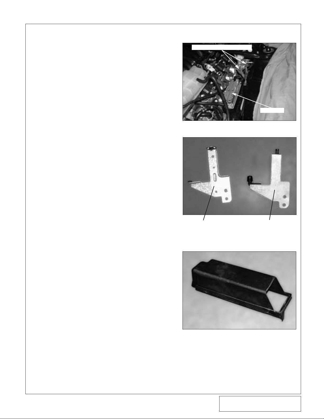
E. Leaving the coolant reser voir hoses connect-
ed, set the reservoir on the engine so that the
area around the computer can be accessed.
(See Fig. 1-a.)
F. Remove the plastic lid from the computer.
(See Fig 1-a.) Remove the two nuts securing
the coolant reservoir bracket.Remove the
screw securing the secondary bracket to the
master cylinder and remove both factory
brackets.
G. Remove the heat shield protecting the com-
puter from the exhaust.
H. Remove the rubber bumper and grommet
stud from the factory reservoir bracket and
install them into the supplied reservoir bracket. (See Fig 1-b.)
I. Modify the plastic computer cover as shown
and reinstall it back over the computer. (See
Fig. 1-c.)
J. Remove the plastic pins securing the plastic
cover over the radiator.Remove the plastic
cover.
K. Remove the factory skid plate.
L. Un-secure the splash panels from under the
front of the vehicle.Remove the splash panels.
M. Remove all hardware securing the front
bumper cover. Below the headlights on each
side of the vehicle the bumper cover snaps to
the bumper. Unsnap these points and remove
the bumper cover from the vehicle.
N. Drain approximately 1 gallon of coolant from
the vehicle.
1. PREPARATION/REMOVAL
Fig. 1-a
Fig. 1-b
Fig. 1-c
FACTORY COOLANT
RESERVOIR BRACKET
VORTECH BRACKET WITH
THE RUBBER BUMPER AND
GROMMET STUD INSTALLED
COOLANT RESERVOIR BRACKETS
COMPUTER
Page 10

2
P/N: 4GJ020-010
©2004 Vortech Engineering, LLC
All Rights Reserved, Intl. Copr.Secured
28SEP04 v1.0 GTO(4GJ020-010v1.0)
O. Locate the valve cover breather on the pas-
sengers side valve cover.Remove the hose
connecting the breather port on the valve
cover to the port on the throttle body.
P. Plug the throttle body port with the supplied
3/8 rubber cap.
Q. Install the supplied Ø3/8 hose from the valve
cover port and run the hose across the
engine to the future location of the supercharger inlet.
Q. Remove the plastic oil fill. Insert the oil fill cap
directly into the valve cover.(See Fig. 2-c.)
1. PREPARATION/REMOVAL, cont’d
Page 11

3
P/N: 4GJ020-010
©2004 Vortech Engineering, LLC
All Rights Reserved, Intl. Copr.Secured
28SEP04 v1.0 GTO(4GJ020-010v1.0)
A. Locate the coils and their bracket on the pas-
senger side of the vehicle.
B. Remove the coils and bracket from the valve
cover as one assembly leaving the plug wires
attached. Let the assembly rest against the
inner fender. Unplug the wiring har ness from
the coil assembly. (See Fig 2-a.)
C. Gently bend the oil dip stick tube forward and
in toward the valve cover. (See Figs 2-a, 2-b.)
D. Using three 6mm x 1.0 x 16mm screws and
washers secure the supplied heat shield to
the lower row of holes on the valve cover.
Make sure the dipstick is located between the
heat shield and the valve cover.
E. Using factory hardware, mount the triangular
coil relocation bracket to the upper rear holes
on the passengers side valve cover.Using
the supplied 6mm x 1.0 x 16mm hardare,
mount the secondary coil relocation bracket
on the upper forward most hole location.
Make sure the threaded holes hang down for
the coil bracket to mount to.(See Fig 2-c.)
F. Using the supplied 6mm x 1.0 x 16mm
screws and washers mount the coil bracket to
the installed relocation brackets. (See Fig.
2-c.)
G. Reconnect the har ness plug.
2. IGNITION COIL RELOCATION
Fig. 2-a
Fig. 2-b
Fig. 2-c
DIPSTICK BENT AGAINST VALVE COVER
3 MOUNTING LOCATIONS
TRIANGULAR RELOCATION BRACKET
OIL FILL CAP
SECONDARY
RELOCATION BRACKET
Page 12

4
P/N: 4GJ020-010
©2004 Vortech Engineering, LLC
All Rights Reserved, Intl. Copr.Secured
28SEP04 v1.0 GTO(4GJ020-010v1.0)
3. COOLANT RESERVOIR MODIFICATIONS
A. Install the supplied coolant reservoir bracket,
containing the factory bumper and grommet
stud, in the same location as the factory
bracket.
B. Remove the grommet stud from the inside
drivers fender wall.
C. Locate the supplied 1" aluminum spacer.
Thread the supplied 6mm stud into one end
half way into the spacer.Thread the grommet
stud into the open end.
D. Thread the spacer, stud and grommet stud
assembly into the factory mounting location.
(See Fig 3-b.)
E. Remove the Ø1" hose from the bottom of the
coolant reservoir.Use the supplied Ø1.0 x
4.0" piece of hose, #16 hose clamps and
Ø1.0 hose mender to lengthen the hose. (See
Fig 3-c.)
F. Modify the computer heat shield as shown in
Fig. 3-d and reinstall it back in the factory
position. (See Fig 3-e.)
Fig. 3-a
Fig. 3-b
Fig. 3-c
NOTE: The brackets will appear the same, but on the
supplied bracket the tabs are bent 180° from
stock. (See Fig 3-a.)
SUPPLIED SPACER WITH GROMMET STUD
SUPPLIED Ø1" x 4" HOSE
Page 13

5
P/N: 4GJ020-010
©2004 Vortech Engineering, LLC
All Rights Reserved, Intl. Copr.Secured
28SEP04 v1.0 GTO(4GJ020-010v1.0)
Fig. 3-d
Fig. 3-e
AREA TO BE TRIMMED
MODIFIED HEAT SHIELD REINSTALLED
3. COOLANT RESERVOIR MODIFICATIONS, cont’d
Page 14

6
P/N: 4GJ020-010
©2004 Vortech Engineering, LLC
All Rights Reserved, Intl. Copr.Secured
28SEP04 v1.0 GTO(4GJ020-010v1.0)
Fig. 4-a
4. OIL FEED
A. Remove the oil filter.
B. Remove the 6mm nuts holding the small cast-
plate located directly above the oil filter. (Set
aside the plate and gasket for later use)
C. Double nut each of the studs and remove
them.
D. Using engine oil on the threads, install the
1/8NPT to –4 90° fitting into the supplied oil
feed adapter.
E. Using the adapter, the supplied factory gasket
and the supplied longer 6mm screws, assemble the components as shown in Fig 4-a.
F. Orient the installed fitting so that it is pointing
away from the engine.
G. Install the oil feed hose onto the open -4 end
of the fitting. Route the oil feed hose so that it
follows the side of the alternator up to the
supercharger mounting location.
ADAPTER BLOCK
1/8NPT TO -4 x 90° FITTING
Page 15

7
P/N: 4GJ020-010
©2004 Vortech Engineering, LLC
All Rights Reserved, Intl. Copr.Secured
28SEP04 v1.0 GTO(4GJ020-010v1.0)
5. OIL DRAIN
A. Un-secure the hard coolant tube mounted to
the cross member directly in front of the oil
pan. Un-secure the power steering line/wiring
bracket located on the bottom lip of the oil
pan. Push these brackets/tubes down to gain
access to the oil drain area. (See Fig 5-a)
B. To provide an oil drain for the supercharger, it
is necessary to make a hole in the oil pan.
Locate and center punch the hole per
Fig 5-b.Drill a 1/8" pilot hole at center location.
C. Use the supplied 9/16" roto broach to drill the
hole in the oil pan.Take care to break through
the pan gently and remove the cut out.
D. Pack the flutes of the 3/8NPT tap with
grease.Tap the hole until the fitting can be
started.
E. Thoroughly clean the threaded area. Reach
inside the oil pan and retrieve any stray chips.
Apply a small amount of sealer to the new
threads. Apply more sealer to the supplied
3/8" NPT x 1/2" barb x 90° fitting and secure
in the hole. Make sure the seal is formed all
around the fitting. Install the supplied 90°
elbow pointing to the drivers side and slightly
up.(See Fig 5-c.)
F. Re-secure the hard coolant tube to the lower
cross member.
G. Install the supplied spacers between the
power steering/wiring bracket and the oil pan
mounting lip with the supplied 8mm x 45mm
long hardware.(See Fig 5-a.)
Fig. 5-b
Fig. 5-c
Fig. 5-a
POWER STEERING LINE AND WIRING
BRACKET TO UNSECURE
SUPPLIED SPACERS
HARD COOLANT TUBE
INSTALLED FITTING
FRONT
VIEW
1.70
.80
Ø9/16
Page 16

8
P/N: 4GJ020-010
©2004 Vortech Engineering, LLC
All Rights Reserved, Intl. Copr.Secured
28SEP04 v1.0 GTO(4GJ020-010v1.0)
6. FUEL INJECTOR REPLACEMENT
A. Relieve the fuel system pressure.
B. Disconnect the eight fuel injector wiring clips
and retainers from the injectors.
C. Remove the four 10mm bolts holding down
the fuel rails on the intake manifold. Lift up
on the rails evenly, removing all eight injectors.
D. Using a small amount of clean motor oil,
lightly lubricate the O-rings on both ends of
the Vor tech supplied fuel injectors.
E. Install the new injectors into the fuel rails with
the terminals facing outward.
F. Carefully lower the fuel rail/injector assembly
down onto the intake manifold. Check to see
that the injector has been seated properly
into the manifold.
G. Tighten down the fuel rail assembly with the
original bolts and attach the wiring clips to the
injector terminals.
NOTE: Do not reinstall factory injector retaining clips
Page 17

9
P/N: 4GJ020-010
©2004 Vortech Engineering, LLC
All Rights Reserved, Intl. Copr.Secured
28SEP04 v1.0 GTO(4GJ020-010v1.0)
7. POWER STEERING RESERVOIR MODIFICATIONS
A. Remove the return line from the power steer-
ing reservoir.
B. Trim the factory hose until there is .50"
remaining before the molded bend.
C. Install the supplied Ø3/8" hose mender and
new 90° molded hose. Secure with the supplied #8 hose clamps. (See Fig 8-e.)
D. Lay the reservoir aside in the engine com-
partment until the reser voir bracket is
installed.
Page 18

10
P/N: 4GJ020-010
©2004 Vortech Engineering, LLC
All Rights Reserved, Intl. Copr.Secured
28SEP04 v1.0 GTO(4GJ020-010v1.0)
8. SUPERCHARGER MOUNTING
G. Using the six supplied 1/4-20 x .75" SHCS
secure the anodized drive pulley on the drive
hub.Torque the screws to 16 ft/lbs. (Blue loctite is recommended on the 1/4" hardware.)
(See Fig. 8-l.)
H. Reinstall the factory belt with the factory belt
routing.
I. Install the oil drain line on the supercharger
and secure it with the supplied #8 hose
clamp.
J. Using a 23/32" dr ill make a hole in the alu-
minum inlet duct as shown in Fig. 8-f. Dr ill the
hole leaving at least .75" from the lip.
K. Install the T-bolt clamp onto the inlet duct,
then place the inlet duct on the supercharger.
Orient the duct as shown in figures 8-g, 8-h.
Tighten the t-bolt clamp so that the inlet duct
is snug.When the supercharger and inlet
duct are installed the clocking of the inlet duct
can be fine tuned.
Fig. 8-a
Fig. 8-b
Fig. 8-c
NOTE: When installing the aluminum drive pulley heat
may be necessary for installation due to tight
tolerances. Do not force the pulley on the hub.
After the pulley is installed spin it to verify that
the hub and pulley are mated flush.
A. Turn the power steering pump sideways and
install the supplied power steering/supercharger drive pulley hub. Make sure that the
hub is seated flush with the end of the
power steering pump shaft.(See Fig. 8-c.)
B. Locate the power steering reservoir bracket.
The engine lift hook will have to be removed
from the bracket.Use a saw or grinder and
remove the section as shown in Fig.8-a.
C. Using two 10mm x 1.5 x 110mm screws,
washers and .430 spacers, secure the mounting bracket to the front of the power steering
pump.Use the .430 spacers between the
pump and back of the plate.(See Fig. 8-c.)
D. For the third mounting location, use a 10mm
x 1.5 x 110mm screw, 10mm washer, 2.2"
spacer, power steering bracket and .880"
spacer.The 10mm screw will pass through
the washer, mounting plate, 2.2" spacer, left
hole in power steering reservoir bracket,
.880" spacer and thread into the head. (See
Fig. 8-d.)
E. Using the other supplied .880 spacer and
10mm x 1.5 x 40mm screw secure the last
hole of the power steering reservoir bracket
into its factory position.
F. Reinstall the power steering reser voir back
into the holder bracket.(See Fig. 8-e.)
Fig. 8-d
.430 SPACERS BETWEEN THE PLATE
AND P/S PUMP IN TWO LOCATIONS
FIRST TWO MOUNTING
LOCATIONS
THIRD MOUNTING
LOCATION
SUPERCHARGER DRIVE HUB
THIRD MOUNTING
PLATE LOCATION
.880" SPACER
SECTION TO BE
REMOVED
Page 19

11
P/N: 4GJ020-010
©2004 Vortech Engineering, LLC
All Rights Reserved, Intl. Copr.Secured
28SEP04 v1.0 GTO(4GJ020-010v1.0)
8. SUPERCHARGER MOUNTING, cont’d
L. Install the 1/8NPT x –4 x 90° fitting into the
supercharger.Orient the fitting down. (See
Fig. 8-h.)
M. Install the supplied 3/8NPT x 3/8 barb into
the 3/8NPT hole in the inlet duct. Insert the
IAT sensor and grommet into the inlet duct.
N. Install the supercharger/inlet duct assembly
onto the mounting bracket and secure with
the supplied 3/8-16 x .75" screws and washers. (It may be necessary to unsnap the
coolant reservoir to install the supercharger
and air inlet duct.)
O. Disconnect the radiator end of the coolant
overflow/return hose and run it below the aluminum A/C line on the driver side and reattach it to the original location. (See Fig 8-j.)
P. Connect the oil drain hose to the fitting at the
pan and secure with a #8 hose clamp.Run
the hose around the side of the alternator
and secure from any sharp objects.
Q. Connect the oil feed line and route it with the
oil drain hose. Secure it away from heat or
sharp objects.
R. Connect the Ø3/8 hose from the passengers
side valve cover to the 3/8" barb on the inlet
duct.
Fig. 8-e
Fig. 8-g
Fig. 8-f
Fig. 8-h
INSTALLED Ø3/8" x 90° MOLDED HOSE
1/8NPT x -4 x 90° FITTING
3/8"NPT x 3/8" BARB
.75" MINIMUM
Page 20

12
P/N: 4GJ020-010
©2004 Vortech Engineering, LLC
All Rights Reserved, Intl. Copr.Secured
28SEP04 v1.0 GTO(4GJ020-010v1.0)
Fig. 8-j
Fig. 8-k
Fig. 8-l
S. Locate the supplied cog belt. Slip it over the
supercharger pulley and the drive pulley.
T. Install the supplied 3/8-16 x 4.25" idler bolt
through the 10mm washer, the flanged aluminum idler, the idler spacer and into the slot
in the top of the supercharger mounting
bracket.(The bearing retainer snap r ing on
the idler must be pointing toward the idler
spacer.Install the supplied nut and washer on
the bolt and tighten until the idler slides up
and down with no play.)
U. Press down on the idler until the belt is snug
with minimal free play. It is not necessar y to
have the belt tight.Once the vehicle has been
started, as long as the belt does not move
around excessively the belt is tight enough.
(See Fig. 8-l.)
COOLANT OVERFLOW HOSE
ROUTED BELOW THE A/C LINE
COOLANT LINE RESTING BETWEEN
BARBS ON INLET DUCT
IDLER AND
SPACER ASSEMBLY
S/C DRIVE PULLEY
INSTALLED
NOTE: Verify that the extended hose from the base of
the coolant reservoir rests between the 3/8" barb
and the 1" bypass bung on the inlet duct. (See
Fig. 8-k.)
Fig. 8-i
8. SUPERCHARGER MOUNTING, cont’d
Page 21

13
P/N: 4GJ020-010
©2004 Vortech Engineering, LLC
All Rights Reserved, Intl. Copr.Secured
28SEP04 v1.0 GTO(4GJ020-010v1.0)
9. AIR INTAKE INSTALLATION
Fig. 9-a
Fig. 9-b
Fig. 9-c
A. Locate the flat inner fender where the factory
air box was mounted.Using a 3.5" hole saw
drill a hole as shown in Fig. 9-a.Remove all
burrs with a file or grinder. (See Fig. 9-e for
location.)
B. Insert the supplied flange into the hole and
secure with the supplied self tapping screw.
C. Secure the air filter to the bottom of the
flange with the supplied #56 hose clamp
located in the fender well.(See Fig 9-c.)
D. Assemble the MAF sensor, flex ducting, 3.5"
x 2" sleeve with #56 hose clamps. The 3.5"
sleeve attaches to the inlet of the MAF sensor and the flex ducting attaches to the outlet.
Verify correct flow for the MAF sensor.
E. Install the silicone sleeve on the open side of
the flange located in the engine compartment. Connect the open end of flex duct to
the cast aluminum inlet duct. Secure both
ends with the supplied #56 hose clamps.(See
Fig 9-d.)
F. Reconnect the IAT and MAF sensors to the
factory harness.
3.5" HOLE
Page 22

14
P/N: 4GJ020-010
©2004 Vortech Engineering, LLC
All Rights Reserved, Intl. Copr.Secured
28SEP04 v1.0 GTO(4GJ020-010v1.0)
Fig. 9-d
Fig. 9-e
9. AIR INTAKE INSTALLATION, cont’d
1.00
DRILL
Ø3.50" HOLE
FRONT OF VEHICLE
.75
Page 23

15
P/N: 4GJ020-010
©2004 Vortech Engineering, LLC
All Rights Reserved, Intl. Copr.Secured
28SEP04 v1.0 GTO(4GJ020-010v1.0)
10. POWER STEERING COOLER RELOCATION
Fig. 10-a
Fig. 10-b
A. Locate the power steering cooler that is
mounted directly in front of the radiator.
Disconnect the cooler from the mounting
straps and let it hang freely. Remove the
mounting straps from the vehicle.
B. Disconnect the power steering cooler hard
lines where they pass along the passenger
side of the radiator at the section of rubber
hose. Remove the power steering cooler and
hard line assembly from the vehicle.
C. Trim the hard lines from the power steering
cooler as shown by Fig.10-a.Make sure to
leave no less than 5/8" after the bends to
allow for the hose connections.
D. Install the supplied L Brackets to the two
bracket mounts on the power steering cooler
that were attached to the factory mounting
straps. Use the supplied 1/4-20 x 1.25 hardware.
E. As shown in Fig. 10-b mount the power steer-
ing cooler with supplied brackets on the lower
cross member and secure with the supplied
self tapping screws.
F. Run two lengths of Ø3/8" hose from the
power steering cooler to the hard lines behind
the radiator.Route the hoses around the passengers side of the radiator and secure the
lines with #8 hose clamps. (See Fig. 10-b.)
G. Bleed system as follows with vehicle off:
1. Raise front wheels off ground
2. Turn steering wheel full left
3. Fill reservoir to "full cold" level. Maintain
level throughout procedure.
4. Turn steering wheel lock to lock at least
20 times or until bubbles stop.
MOUNTING STRAPS
TO BE REMOVED
2 LENGTHS OF Ø3/8 HOSE LEADING
BACK TO THE FACTORY HARD LINES
AREA TO TRIM COOLER
SUPPLIED L-BRACKETS
Page 24

16
P/N: 4GJ020-010
©2004 Vortech Engineering, LLC
All Rights Reserved, Intl. Copr.Secured
28SEP04 v1.0 GTO(4GJ020-010v1.0)
11. DISCHARGE INSTALLATION
Fig. 11-b
Fig. 11-c
Fig. 11-d
A. Attach the supplied piece of foam tape to the
bottom of the charge cooler.Lay the charge
cooler on the passengers’ side of the motor
above the relocated coils.Position the cooler
close to the oil fill cap.Or ient the charge cooler so that the 1/2NPT ports are pointing
toward the front of the car. Install the 90° 1/2
NPT brass fitting in the upper passenger side
port and the 1/2 NPT straight brass fitting is
in the lower drivers’side por t. (See Figs.11-a,
11-b.)
B. Install the supplied Ø2.75" x 2" sleeve on the
discharge of the supercharger.Install the supplied Ø2.75" x 3" sleeve on the inlet of the
charge cooler.
C. Install the longer straight section of the
S-shaped discharge tube into the Ø2.75 x 2"
sleeve on the supercharger and the opposite
end in the sleeve located on the cooler. Snug
the discharge tube in place with #44 hose
clamps.
D. Install the Ø2.75 end of the reducer sleeve on
the outlet of the charge cooler.Install the
3.88" end of the 90° elbow on the throttle
body pointing toward the passenger side.
(See Fig. 11-d.)
E. Install the L-shaped discharge duct with the
shortest leg leading into the Ø3.0 end of the
reducer sleeve. The other end of the tube will
go into the open end of the silicone elbow on
the throttle body. Snug with the supplied #48
and #64 hose clamps. (See Fig. 11-d.)
F. Orient the ducting for best fit then tighten all
hose clamps. #44 hose clamps are for all
Ø2.75 ends, #48 clamps are for all Ø3.00
ends and the #64 hose clamp is for the throttle body.
G. Connect the 6" piece of Ø1.0 bypass hose to
the pressure side of the bypass.
“S” SHAPED DISCHARGE TUBE
90° SILICONE ELBOW
Fig. 11-a
1/2"NPT x 90° FITTING
1/2"NPT STRAIGHT FITTING
Page 25

17
P/N: 4GJ020-010
©2004 Vortech Engineering, LLC
All Rights Reserved, Intl. Copr.Secured
28SEP04 v1.0 GTO(4GJ020-010v1.0)
11. DISCHARGE INSTALLATION, cont’d
Fig. 11-e
Fig. 11-f
Fig. 11-g
H. Trim and orient the supplied molded Ø1.0
long 45° as shown in Fig.11-e.
I. Connect the open end of the straight bypass
hose to the Ø1.0 bung on discharge tube A.
Connect the open end of the 45° molded
hose to the Ø1.0 bung on the inlet duct.
Secure the ends with #16 hose clamps. (See
Fig. 11-g.)
J. Cut into the brake booster hose as shown
(see Fig. 11-f) and insert the supplied brass
TEE fitting.
K. Connect the 5/32" vacuum line from the
bypass valve nipple to the installed TEE fitting.
6" PIECE OF Ø1.00 HOSE
THAT CONNECTS TO THE
DISCHARGE TUBE
TRIMMED 45° HOSE
THAT CONNECTS TO
THE INLET TUBE
SUPPLIED BRASS
TEE FITTING
Page 26

18
P/N: 4GJ020-010
©2004 Vortech Engineering, LLC
All Rights Reserved, Intl. Copr.Secured
28SEP04 v1.0 GTO(4GJ020-010v1.0)
12. WATER RESERVOIR/SETRAB COOLER INSTALLATION
Fig. 12-a
Fig. 12-b
Fig. 12-c
A. Locate the supplied water reservoir.Using
thread sealant install a Ø3/4" 90° brass fitting
into the 1/2NPT hole at the top of the reservoir. Install another 90° fitting into the bottom
1/2NPT hole.
B. Install a 2" piece of Ø3/4" hose on the top
90° fitting. Secure it with a supplied nylon
ratchet clamp and orientate it so that it will be
pointing to the passenger side. Orientate the
bottom fitting so that it will be pointing to the
driver side. (See Fig. 12-a.)
C. Secure the upper mounting bracket to the
1/4-20 threaded insert in the top of the reservoir. Mount the lower bracket on the drivers’
side of the tank. Use the supplied 1/4-20 x
.75 SHCS to secure the brackets. (See Fig.
12-a.)
D. Place the reservoir and brackets into their
location behind the front bumper on the far
passengers side. Mark for drill locations. (See
Figs. 12-b, 12-c.)
E. Remove the reservoir and brackets.Use a
self tapping screws to drill the upper hole.
Remove the screw after the hole is started.
For the lower mounting location use a .280"
drill to make a mounting hole in the lower
cross member.(See Figs. 12-b,12-c.)
F. Reinstall the reservoir and secure the upper
bracket with the supplied sheet metal screw.
G. Install the Ø3/4" 90° brass fittings into the top
of the supplied Setrab water cooler. Orientate
the fittings as shown in Fig. 12-d. Install the
cooler to the right of the water reservoir.The
passenger side of the water cooler will share
a mounting hole with the lower bracket of the
water reservoir. (See Fig. 12-e.)
H. Secure the passenger side of the Setrab
cooler and the bottom reservoir bracket to the
cross member with the supplied 1/4-20 x
1"SHCS.
I. Mark the driver side location of the Setrab
cooler and drill with a .280 drill. Secure the
driver side of the cooler with the supplied 1/420 x 1" hardware. Make sure when mounting
the Setrab cooler that you use the rear set of
holes so that the cooler sits forward when
mounted.
UPPER MOUNTING BRACKET
LOWER MOUNTING BRACKET
UPPER MOUNT LOCATION TO DRILL
LOWER MOUNT LOCATION THAT THE
WATER COOLER AND RESERVOIR
ARE TO SHARE
Page 27

19
P/N: 4GJ020-010
©2004 Vortech Engineering, LLC
All Rights Reserved, Intl. Copr.Secured
28SEP04 v1.0 GTO(4GJ020-010v1.0)
12. WATER RESERVOIR/SETRAB COOLER INSTALLATION, cont’d
Fig. 12-d
Fig. 12-e
Fig. 12-f
Fig. 12-g
J. Trim the supplied Ø3/4 x 90° molded hoses.
See Fig. 12-g for hose lengths.
K. Installed the 2-3/4 end of the trimmed 90°
molded elbow on the passenger side fitting in
the water cooler. Orient the hose as shown in
Fig. 12-d.
L. With the cooler and reser voir mounted, install
the aluminum section of water tube so that it
snakes around the upper passenger side of
the radiator down to the 2" piece of rubber
hose installed on the reservoir.Push the aluminum tube into the hose and secure with a
supplied nylon ratchet clamp.(See Fig. 12-f.)
SHARED MOUNTING LOCATION
2" PIECE OF Ø1.0" HOSE
ON WATER RESERVOIR
6.5
2.75
4.75
6.5
Page 28

20
P/N: 4GJ020-010
©2004 Vortech Engineering, LLC
All Rights Reserved, Intl. Copr.Secured
28SEP04 v1.0 GTO(4GJ020-010v1.0)
13. WATER PUMP AND HOSE INSTALLATION
Fig. 13-a
Fig. 13-b
Fig. 13-c
A. Mount the supplied water pump relay onto the
inside passenger side fender behind the fuse
box. (See Fig. 13-a.)
B. Connect the red 12GA wire from terminal #30
to the supplied fuse holder using the supplied
butt connector. Install a yellow ring terminal
on the other end of the fuse holder and bolt it
to the fuse box power supply terminal as
shown.
C. Feed the yellow wire from relay terminal #85
to the fuse box on the passengers side of the
engine bay. Route the wire to the stock fuel
pump relay and connect using the supplied
fuse tap.(See Fig. 13-b.)
D. Run the black wire from terminal #86 on the
water pump relay terminal to ground.
E. With the long red 12-GA wire connected to
terminal #87, route the free end down to the
front of the vehicle where the water pump will
be located. Secure as necessary to avoid
heat and sharp edges.
F. Mount the water pump to the lower cross
member on the side of the water cooler with
the supplied adel clamps and self tapping
screws.Connect a 14-16GA r ing ter minal to
the brown wire on the water pump and connect it to one of the mounting screws for
ground. (See Fig. 13-c.)
G. Using the supplied slide connectors connect
the red wire from the relay to the positive
blue/green wire off the water pump.
H. Connect the discharge of the water pump to
the inlet of the water cooler with the trimmed
Ø3/4" x 4-3/4 x 6 1/2 molded 90° hose.
Secure the ends with nylon ratchet clamps.
(See Fig. 12-g.)
I. Cut a 23" piece of Ø3/4" hose and connect
the bottom fitting on the water reservoir to the
inlet of the water pump and secure with nylon
ratchet clamps.
WATER PUMP
RELAY
YELLOW WIRE FROM
TERMINAL #85
RED WIRE FROM
TERMINAL #30
Page 29

21
P/N: 4GJ020-010
©2004 Vortech Engineering, LLC
All Rights Reserved, Intl. Copr.Secured
28SEP04 v1.0 GTO(4GJ020-010v1.0)
13. WATER PUMP AND HOSE INSTALLATION, cont’d
Fig. 13-d
Fig. 13-f
Fig. 13-g
J. Install the S-shaped water tube so that the
long end is inserted into the 90° elbow on the
charge cooler.With the long end in place, verify that the open end id pointing down and
runs behind the battery.(See Figs. 13-g,
13-h.)
K. Cut a 50" piece of Ø3/4" hose. Connect one
end of the cut hose to the 90° molded hose
off the outlet of the water cooler using a supplied barbed hose mender.Secure with ratchet clamps. Route the hose below the passenger side head light, into the fender well and
bring it into the engine compartment from
behind the battery. (See Figs. 13-a, 13-d.)
Connect the open end of the 50" hose to the
open end of the aluminum water tube.(It may
be easier to remove the battery before routing this hose.) Secure all ends with ratchet
clamps.
L. Cut a 19" piece of Ø3/4" hose. Connect the
open end of the aluminum water tube near
the radiator to the straight fitting in the charge
cooler.Secure the ends with nylon ratchet
clamps.(See Fig. 13-e.)
HOSE ROUTED BEHIND HEADLIGHT
Fig. 13-h
Page 30

22
P/N: 4GJ020-010
©2004 Vortech Engineering, LLC
All Rights Reserved, Intl. Copr.Secured
28SEP04 v1.0 GTO(4GJ020-010v1.0)
6.50
4.75
2.75
6.5
6.5
3/4" HOSE MENDER
2" PIECE OF
Ø3/4" HOSE
19" PIECE OF HOSE
50" PIECE OF HOSE
FLOW
FLOW
2 x 90° BRASS FITTING
23" PIECE OF Ø3/4" HOSE
WATER PUMP
WATER
RESERVOIR
ALUMINUM
WATER TUBE
SETRAB COOLER
CHARGE COOLER
S-SHAPED ALUMINUM
WATER TUBE
4.5
Fig. 13-e
13. WATER PUMP AND HOSE INSTALLATION, cont’d
Page 31

14. REFLASH COMPUTER
Fig. 14-a
A. Reconnect the battery.
B. Locate the vehicles OBD2 connector located
below the dash on the drivers side of the
vehicle.
C. Attach the OBD2 connector from the Flash
tool that is provided in the kit to the vehicle’s
OBD2 port. Make sure this connector is seated all the way in the vehicles OBD2 port. You
do not want this connector coming out during
programming or damage may occur to the
vehicle’s ECM.
D. The Reflash tool should power up and display
three parameters.
1. Perf ormance Tune
2. Diagnostics
3. Options
E. Select “Performance Tune” and press the
enter button in the middle of the arrow keys.
F. Read the disclaimer entirely, then select
agree and press ENTER.
G. At this point follow the instructions on the
screen of the screen displayed on the reflash
tool. If you have any questions, either refer to
the manual that is provided with the reflash
tool or contact our service depar tment for further assistance.
H. Turn the ignition on (do not star t the vehicle).
Set the parking brake and press the ENTER
button to continue.
I. SELECT TUNE will be displayed at the top of
the screen. Use the arrow keys to select the
appropriate tune for your vehicle and press
the ENTER button.You will have a choice of
two to choose from:
1. Vortech GTO H.O.
2. Original Backup
J. Continue to follow the screen and when fin-
ished unplug the reflash tool from the vehicles OBD2 port.
IMPORTANT! To ensure trouble-free programming of your vehicle's computer:
• Make sure the vehicle's battery is sufficiently charged.
• Turn off all accessories and close doors to prevent unnecessary drain on the battery.
• Do not attempt to program your vehicle while a battery charger is connected.
• Improper battery voltage will result in failure of the programming process.
• Do not disconnect the cable or turn off the ignition during programming.
NOTE: Do not disturb the cable, or turn the
ignition off during this time. If the programming is disrupted, the computer
will not start or run your vehicle!
Fig. 14-b
ESCAPE
ENTER
OR
SELECT
ARROW
KEYS
0BD2 CONNECTOR
23
P/N: 4GJ020-010
©2004 Vortech Engineering, LLC
All Rights Reserved, Intl. Copr.Secured
28SEP04 v1.0 GTO(4GJ020-010v1.0)
Page 32

DP/N: 4GJ020-010 v1.0 09/20/04
1650 PACIFIC AVENUE • CHANNEL ISLANDS, CA 93033-9901 • (805) 247-0226
FAX (805) 247-0669 • www.vortechsuperchargers.com • M-F 8:00 AM - 4:30 PM PST
ENGINEERING, LLC
15. FINAL ASSEMBLY AND CHECK
A. If your vehicle has gone over 20,000
miles since its last spark plug change, it
is a good idea to change the spark plugs
now, before test driving.
B. Make sure that oil drain to oil pan fitting
is tight and that the engine is filled with
factory specified oil
C. Make sure radiator and overflow tank are
filled .
D. Make sure that the vehicle is filled with
91 octane fuel or higher before commencing test drive.
E. With key on, make sure charge air cooler
water pump is operating and the water is
flowing through the surge tank. Fill as
necessary. If water is not flowing, remove
the hose from the bottom of the surge
tank and lower until water flows out of
the hose.This should prime the pump.
Reconnect the hose, verify the water flow
and top off the surge tank. Do not run the
water pump for extended periods (30
seconds or more) without water flow.
F. Check all fittings, nuts, bolts and clamps
for tightness.
G. At this point it is OK to start the vehicle.
H. Verify that the belt is tracking properly
with the vehicle running.
I. With engine running, check power steer-
ing hose connections for leakage.Let the
engine run for two minutes.Turn steer ing
wheel in both directions.
Verify:
• Smooth power assist
• Noiseless operation
• Proper fluid level
• No system leaks
• No bubbles, foam or discoloration in
fluid.
J. Turn the vehicle off and recheck all fluid
levels, verify that no hoses, wires, etc are
near exhaust headers or moving parts
and that there is no fluid leakage.
K. Test drive the vehicle by gradually work-
ing up to full throttle and paying close
attention to any abnormal sounds or
engine detonation.
WARNING: Do not attempt to operate the vehicle until
ALL components are installed and ALL
operations are completed including final
check. Failure to do so may cause PREMATURE FAILURE OF MAJOR COMPONENTS.
®
 Loading...