

Page 1
DP/N: 4LA020-010 - v1.1 07/10/07
1650 Pacific Avenue, Channel Islands CA 93033-9901 • Phone: 805 247-0226
Fax: 805 247-0669 • www.vortechsuperchargers.com • M-F 8:00AM - 4:30PM (PST)
ENGINEERING, LLC
Lexus
3.0L IS300
Supercharger System
Installation Instructions
2001-2005 Model Year
*Legal in California only for racing vehicles which may never be used upon a highway.
®
Page 2

P/N: 4LA020-010
©2007 Vortech Engineering, LLC
All Rights Reserved, Intl. Copr. Secured
11JUL07 v1.1 Lexus(4LAv1.1)
ii
FOREWORD
©2007 VORTECH ENGINEERING, LLC
All rights reserved. No part of this publication may be reproduced, transmitted, transcribed, or translated
into another language in any form, by any means without written permission of Vortech Engineering, LLC.
Take note of the following before proceeding:
1. Proper installation of this supercharger kit requires general automotive
mechanic knowledge and experience. Please browse through each step of
this instruction manual prior to beginning the installatlion to determine if you
should refer the job to a professional installer/technician. Please contact
your dealer or Vortech Engineering for possible installers in your area.
2. This product was designed for use on stock (un-modified, OEM) vehicles. The
PCM (computer), engine, transmission, drive axle ratios and tire O.D. must be stock. If
the vehicle or engine has been modified in any way, check with Vortech prior to installation and use of this product.
3. Use only premium grade fuel with a minimum of 91 octane (R+M/2).
4. Always listen for any sign of detonation (knocking/pinging) and discontinue hard use (no
boost) until the problem is resolved.
5. Vo r tech is not responsible for any clutch, transmission, drive-line or engine damage.
Exclusions from Vortech warranty coverage considerations include, but
not limited to:
1. Neglect, abuse, lack of maintenance, abnormal operation or improper installation.
2. Continued operation with an impaired vehicle or sub-system.
3. The combined use of Vortech components with other modifications such as, but not limit-
ed to, exhaust headers, aftermarket camshafts, nitrous oxide, third party PCM programming or other such changes.
T
his manual provides information on the installation, maintenance and service of the
Vor tech supercharger kit expressly designed for this vehicle. All information, illustra-
tions and specifications contained herein are based on the latest product information
available at the time of this publication. Changes to the manual may be made at any time
without notice. Contact Vortech Engineering for any additional information regarding this kit
and any of these modifications at (805) 247-0228 8:00am-4:30pm PST.
NOTICE
Due to variances in each vehicle, Vortech recommends that the vehicle get
a “custom tune” from a local, reputable tuner.
This kit is supplied with a “universal” fuel and ignition timing calibration. This
calibration is intended to allow the vehicle to start and operate at part throttle, and is not optimized for full throttle performance. Do not operate the
vehicle at heavy throttle or high RPM until a custom calibration tailored for
your specific vehicle can be obtained from a competent tuner. A “wideband” exhaust oxygen sensor must be used to confirm proper air/fuel ratio.
Vortech suggests a proper WOT air/fuel ratio range of 10.8-11.0:1 for 91
octane fuel.
STOP
Page 3

P/N: 4LA020-010
©2007 Vortech Engineering, LLC
All Rights Reserved, Intl. Copr. Secured
11JUL07 v1.1 Lexus(4LAv1.1)
iii
TABLE OF CONTENTS
FOREWORD . . . . . . . . . . . . . . . . . . . . . . . . . . . . . . . . . . . . . . . . . . . . . . . . . . .ii
TABLE OF CONTENTS . . . . . . . . . . . . . . . . . . . . . . . . . . . . . . . . . . . . . . . . . .iii
IMPORTANT NOTES . . . . . . . . . . . . . . . . . . . . . . . . . . . . . . . . . . . . . . . . . . . .iv
TOOL & SUPPLY REQUIREMENTS . . . . . . . . . . . . . . . . . . . . . . . . . . . . . . . . .v
PARTS LIST (2002-2005 3.0L Lexus) . . . . . . . . . . . . . . . . . . . . . . . . . . . . . . .vi
1. PREPARATION/REMOVAL . . . . . . . . . . . . . . . . . . . . . . . . . . . . . . . . . . . .1
2. OIL FEED . . . . . . . . . . . . . . . . . . . . . . . . . . . . . . . . . . . . . . . . . . . . . . . . .4
3. OIL DRAIN . . . . . . . . . . . . . . . . . . . . . . . . . . . . . . . . . . . . . . . . . . . . . . . .5
4. ABS RELOCATION . . . . . . . . . . . . . . . . . . . . . . . . . . . . . . . . . . . . . . . . . .6
5. MOUNTING BRACKET AND SUPERCHARGER INSTALLATION . . . . . . .7
6. CHARGE COOLER INSTALLATION . . . . . . . . . . . . . . . . . . . . . . . . . . . . .10
7. AIR INLET INSTALLATION . . . . . . . . . . . . . . . . . . . . . . . . . . . . . . . . . . . .19
8.1 FUEL MANAGEMENT UNIT (FMU) RECALIBRATION (2003
Automatic Models Only) . . . . . . . . . . . . . . . . . . . . . . . . . . . . . . . . . . . . . .21
8.2 FUEL PUMP AND FMU INSTALLATION . . . . . . . . . . . . . . . . . . . . . . . . . .23
9. POWER STEERING . . . . . . . . . . . . . . . . . . . . . . . . . . . . . . . . . . . . . . . .26
10. ELECTRONIC CONTROL BOX INSTALLATION . . . . . . . . . . . . . . . . . . . .27
11. FINAL CHECK . . . . . . . . . . . . . . . . . . . . . . . . . . . . . . . . . . . . . . . . . . . . .29
Page 4

P/N: 4LA020-010
©2007 Vortech Engineering, LLC
All Rights Reserved, Intl. Copr. Secured
11JUL07 v1.1 Lexus(4LAv1.1)
iv
This product is protected by state common law, copyright and/or patent. All
legal rights therein are reserved. The design, layout, dimensions, geometry,
and engineering features shown in this product are the exclusive property
of Vortech Engineering, LLC. This product may not be copied or duplicated
in whole or part, abstractly or fundamentally, intentionally or fortuitously, nor
shall any design, dimension, or other information be incorporated into any
product or apparatus without prior written consent of Vortech Engineering,
LLC.
IMPORTANT NOTE
2001-2005 3.0L Lexus IS300
Page 5
P/N: 4LA020-010
©2007 Vortech Engineering, LLC
All Rights Reserved, Intl. Copr. Secured
11JUL07 v1.1 Lexus(4LAv1.1)
v
Before beginning this installation, please read through this entire instruction booklet and the
Street Supercharger System Owner’s Manual which includes the Limited Warranty Program,
the Warranty Registration form and return envelope.
Vor tech supercharger systems are performance improving devices. In most cases, increases in
torque of 30-35% and horsepower between 35-45% can be expected with the boost levels specified
by Vor tech Engineering. This product is intended for use on healthy, well maintained engines.
Installation on a worn-out or damaged engine is not recommended and may result in failure of
the engine as well as the supercharger. Vortech Engineering is not responsible for engine
damage.
Installation on new vehicles will not harm or adversely affect the break-in period so long as factory
break-in procedures are followed.
For best performance and continued durability, please take note of the following key points:
1. Use only premium grade fuel 91 octane or higher (R+M/2).
2. The engine must have stock compression ratio.
3. If the engine has been modified in any way, check with Vortech prior to using this product.
4. Always listen for any sign of detonation (pinging) and discontinue hard use (no boost)
until problem is resolved.
5. Perform an oil and filter change upon completion of this installation and prior to test driving
your vehicle. Thereafter, always use a high grade SF rated engine oil or a high quality synthetic, and change the oil and filter at least every 3,000 miles. Never attempt to extend the
oil change interval beyond 3,000 miles, regardless of oil manufacturer’s claims as
potential damage to the supercharger may result.
6. Before beginning installation, replace all spark plugs that are older than 1-year or 15,000
miles with original heat range plugs as specified by the manufacturer and reset timing to factory specifications (follow the procedures indicated within the factory repair manual and/or as
indicated on the factory underhood emissions tag). Do not use platinum spark plugs
unless they are original equipment. Change spark plugs every 20,000 miles.
TOOL & SUPPLY REQUIREMENTS
• Factory repair manual
• 3" hole saw
• 1/2" socket and drive set: SAE & metric
• 3/8-18 tap & handle
• Adjustable wrench
• Open end wrenches: 3/8", 7/16", 1/2", 9/16",
10mm, 12mm
• Metric Allen wrench set
• Center punch and a 5/8" tapered punch
• Fractional drill bit set
• Grinder (electric right-angle)
• 6 quarts (or what is specified in your owner’s manual)
SF rated quality engine oil, oil filter and wrench
If it has been 20,000 miles or more since your vehicle’s last spark plug change, then you will also need:
• Spark plug socket
• NEW spark plugs
2001-2005 3.0L Lexus IS300
Installation Instructions
Congratulations on selecting the best performing and best backed automotive
supercharger available today... the VORTECH® supercharger!
®
ENGINEERING, LLC
Page 6
P/N: 4LA020-010
©2007 Vortech Engineering, LLC
All Rights Reserved, Intl. Copr. Secured
11JUL07 v1.1 Lexus(4LAv1.1)
vi
008110 SMALL SILVER DIE-CUT DECAL 2
008130 LICENSE PLATE FRAME, VORTECH 1
008444 S/C STRT INFO PKG ASY VORT 1
2E248-080 SUPERCHARGER V-5F SQ CW, LEXUS IS300 1
4LA020-010 INSTRUCTION MANUAL, IS300 1
4LA110-010 POWER STEERING COOLR ASY 1
8N006-025 COOLER, P/S 4-PASS PERMA/CL 1
8N100-001 NYLON MOUNTING KIT 1
7P375-312 3/8" BARB x 5/16" BARB REDUCER 2
7R004-003 STEPLESS CLAMP, 14.5-70 4
7U031-018 5/16" EFI FUEL HOSE HI-PSR 4'
4LA111-044 S/C MOUNT BRKT ASY, LEXUS IS300 1
2A017-462 SPACER, IDLER SMOOTH 6-RIB 1
2A017-501-153 SPACER, .50"OD x 1.538"L ALUM 1
2A017-750-08 SPACER, .75"OD x .1.437"L 1
2A017-875-13 SPACER, .875"OD x .895"L 5
2A046-100 BELT, GATES K061010 1
4FA016-171 DUST COVER (IDLER PULLEY) 2
4FH016-150 IDLER PULLEY, 6-RIB 3" FLANGED 2
4LA010-010 BRKT, SUPPORT IS300 1
4LA010-021 BRKT, LOWER SUPPORT IS300 1
4LA010-044 BRKT, 5/16" S/C MOUNT IS300 1
4LA017-011 SPACER, IDLER, 1.060"L IS300 1
7A375-100 3/8-16 x 1" G5 HHCS PLT 2
7A375-100 3/8-16 x 1" G5 HHCS PLT 1
7A375-178 3/8-16 x 1-3/4" HXHD G8 5
7A375-276 3/8-16 x 2-3/4" HXHD ZINC 1
7C010-016 M10-1.25 x 16mm, FLG HD, 10.9 1
7C012-040 M12-1.75 x 40mm HXHD BOLT, CL10.9 1
7C060-070 M6-1.00 x 70mm HXHD CL8.8 PLT 2
7C080-040 M8-1.25 x 40mm, SHCS, CL12.9 1
7C080-081 M8-1.25 x 80mm, HXHD, CL10.9 1
7E010-075 #12 x 3/4" SHT METAL SCRW, HEX 3
7F375-017 3/8-16 NYLOCK NUT 2
7J006-094 6mm WASHER SS 2
7K312-001 5/16"AN WASHER, PLATED 1
7K375-040 3/8"AN960 FLAT WASHER PLATED 12
4LA112-010 INLET ASY, LEXUS IS300
8H040-035 AIR FILTER, 3.5" FLANGE, G35 OFFSET 1
7U030-036 1/2" OIL DRAIN HOSE 0.75'
7P500-001 1/2" HOSE UNION 2
7R001-006 #6 STNLS HOSE CLAMP, NARROW 3
7U031-016 5/16" PCV/VAC RUBBER HOSE 2.5'
7R004-003 STEPLESS CLAMP, 14.5-70 4
7P312-050 5/16" HOSE MENDER 1
7P312-060 ELBOW, PLASTIC 5/16" x 90° UNION 1
4LA130-026 OIL FEED LINE ASY, IS300 1
7P125-004 1/8"NPT x 90° x -4 JIC FTG STL 1
7P125-005 1/8"NPT STR x -4 JIC FTG STL 1
7P125-034 1/8"NPT x 1/8"NPT STRT T 1
7P125-125 FTG, 1/8"NPT FEM x 1/8"BSPT MALE 1
7U100-055 TIE-WRAP, 7.5" NYLON 5
7U250-090-320 OIL FEED HOSE, 32" x -4 x 90° 1
4NZ101-068 FUEL PUMP ASY, INLINE 350Z 1
5W001-045 16-14GA RING TERM., .17" HOLE 1
5W001-032 1/4" WIRE LOOM 10'
5W001-011 16-14GA RING TERM. .26" HOLE 1
5W014-030 14GA STRD WIRE BLACK .5'
7E010-075 #12 x 3/4" SHT METAL SCREW, HEX 2
7P312-017 5/16" HOSE BARB TO M10 x 1.0mm 1
7P312-082 5/16" TEE HOSE BARB 2
7R003-027 ADEL CLAMP, 1-11/16" 2
7R004-001 STEPLESS CLAMP, 15.7-70 8
PART NO. DESCRIPTION QTY PART NO. DESCRIPTION QTY.
7U031-0018 5/16" EFI HOSE, HI-PSR 5.5'
7U100-044 TIE-WRAP, 4" NYLON 10
7U100-055 TIE-WRAP, 7.5" NYLON 5
8F001-068 WALBRO INLINE FUEL PUMP, 68 GP 1
4NZ130-036 OIL DRAIN LINE ASY, 350Z 1
7P375-017 3/8"NPT x 1/2" BEADED HSE BARB 1
7R001-008 #8 STNLS HOSE CLAMP 2
7T560-001 CUTTER, 9/16" ROTABROACH 1
7T560-002 ARBOR, ROTABROACH 1
7U030-036 1/2" OIL DRAIN HOSE 1.5'
7U100-066 TIE-WRAP, 11" NYLON 5
4NZ238-088 FMU, 8:1 w/LINES, w/SPRING, 3 1
6Z010-101 FMU HOUSING (BLUE ANODIZED) 1
6Z010-111 FMU VALVE BODY (BLUE ANODIZED) 1
6Z010-131 COVER, FMU - GM 4.3 1
6Z020-130 SML DIAPHRAGM, FLUORO 1
6Z020-140 LRG DIAPHRAGM, FLOURO 1
6Z030-150 BRACKET, FMU 1
6Z040-160 PISTON, FMU 1
6Z050-191 FMU WASHER, 8:1 PLATED 1
6Z060-181 SHIM, FMU 1
6Z070-030 FMU 8:1 RING SPACER 1
6Z080-011 RETAINER, FMU SPRING GM 4.3 1
6Z090-010 SPRING, FMU GM 4.3 1
7C010-050 10-24 x .50" SHCS GR8 PLT 6
7C010-075 10-24 x 3/4" SHCS GR5 ZINC 4
7C024-025 10-24 x 1/4" PHILL HD 3
7E010-075 #12 x 3/4" SHT MTL SCRW, HEX 2
7P125-025 1/8"NPT x 5/32" HOSE, 90° 1
7P125-031 1/8"NPT x 90° x 5/16" BARB 1
7P125-032 1/8"NPT-STR, 5/16" BARB 1
7P156-082 5/32" TEE 1
7P312-005 5/16" FEM FUEL CNCT, STEEL 1
7P312-007 FUEL FTG, 5/16" GM x 5/16" HSE 1
7R004-001 STEPLESS CLAMP, 15.7-70 4
7U030-046 5/32" VACUUM LINE 7'
7U031-018 5/16" EFI FUEL HSE, HI-PSR 2.5'
7U031-018 5/16" EFI FUEL HSE, HI-PSR 1.25'
7U100-030 O-RING, FMU 1
7U100-096 ROLL PIN, 3/16" x 1/2" SS 1
5A003-130 ECU, UNICHIP QT, '02-'05 IS300 SAFE TUNE 1
8N201-330 CHARGE COOLR ASY, LEXUS IS300 1
4LA010-061 BRKT, HOOD LATCH SPRT IS300 1
4LA012-010 TUBE “A” S/C DISCHARGE IS300 1
4LA012-020 TUBE “B” S/C DISCHARGE IS300 1
4LA012-040 TUBE “D” S/C DISCHARGE IS300 1
4LA012-050 TUBE “E” S/C DISCHARGE IS300 1
4NZ012-020 TUBE, COOLER INLET, 350Z 1
7A250-074 1/4-20 x .75" HHCS PLTD 1
7A312-050 1/4-20 x 1/2" HXHD GR5 ZINC 2
7C008-050 #8-32 x 1/2" SHCS, ZINC 2
7E010-049 #10 x 3/4" HXHD SLF DRL SHT MTL 2
7F250-021 1/4-20 NYLOCK NUT ZINC PLATED 1
7J006-094 6mm WASHER SS 4
7P156-082 5/32" TEE 1
7R002-016 #16 SAE TYPE “F” SS HOSE CLAMP 2
7R002-040 #40 SAE TYPE “F” SS HOSE CLAMP 12
7R002-044 #44 SAE TYPE “F” SS HOSE CLAMP 2
7S250-025 ELBOW, 2.5"ID x 25° BLUE 5
7U030-046 5/32" VACUUM LINE 3'
7U133-090 RUBBER ELBOW, Ø1.0" x 90° 1
8D001-001 STD COMPRESS BYPASS VALVE 1
8H040-075 1" AIR FILTER BYPASS 1
8N010-210 BRKT, CLR MNT, IS300 1
8N101-350 CHARGE AIR COOLER, 350Z 1
7S300-275 REDUCER, 3.00" x 2.75" 2
IMPORTANT: Before beginning installation, verify that all parts are included in the kit. Report any shortages or damaged parts
immediately.
2002-2005 3.0L Lexus
Part No. 4LA218-010SQ/018SQ
®
ENGINEERING, LLC
PARTS LIST
Page 7
P/N: 4LA020-010
©2007 Vortech Engineering, LLC
All Rights Reserved, Intl. Copr. Secured
11JUL07 v1.1 Lexus(4LAv1.1)
vii
8F101-350 RELAY ASY, 350Z FUEL PUMP 1
5W001-005 3/8" PLASTIC WIRE LOOM 8'
5W001-010 16-14GA FEMALE SLIDE INSULATED 2
5W001-016 RELAY, BOSCH 1
5W001-040 12-10GA FEMALE SLIDE INSULATED 2
5W001-046 16-14GA RING TERM. .33" HOLE 2
5W001-054 16GA FUSE HOLDER WITH WIRE 1
5W014-010 14GA STRD WIRE, RED, UL1015 7'
5W014-030 14GA STRD WIRE BLACK 1'
5W014-030 14GA STRD WIRE BLACK 7'
6Z170-040 10:1 RING SPACER ASY 1
PART NO. DESCRIPTION QTY PART NO. DESCRIPTION QTY.
IMPORTANT: Before beginning installation, verify that all parts are included in the kit. Report any shortages or damaged parts
immediately.
2002-2005 3.0L Lexus, cont’d
Part No. 4LA218-010SQ/018SQ
®
ENGINEERING, LLC
PARTS LIST
Page 8

P/N: 4LA020-010
©2007 Vortech Engineering, LLC
All Rights Reserved, Intl. Copr. Secured
11JUL07 v1.1 Lexus(4LAv1.1)
viii
This Page Left Intentionally Blank
Page 9
P/N: 4LA020-010
©2007 Vortech Engineering, LLC
All Rights Reserved, Intl. Copr. Secured
11JUL07 v1.1 Lexus(4LAv1.1)
1
A. Disconnect the negative battery cable.
B. Remove the four 10mm headed fasteners
securing the plastic engine cover and set
aside.
C. Disconnect the valve cover vent hose from
the air inlet assembly but leave it attached to
the valve cover.
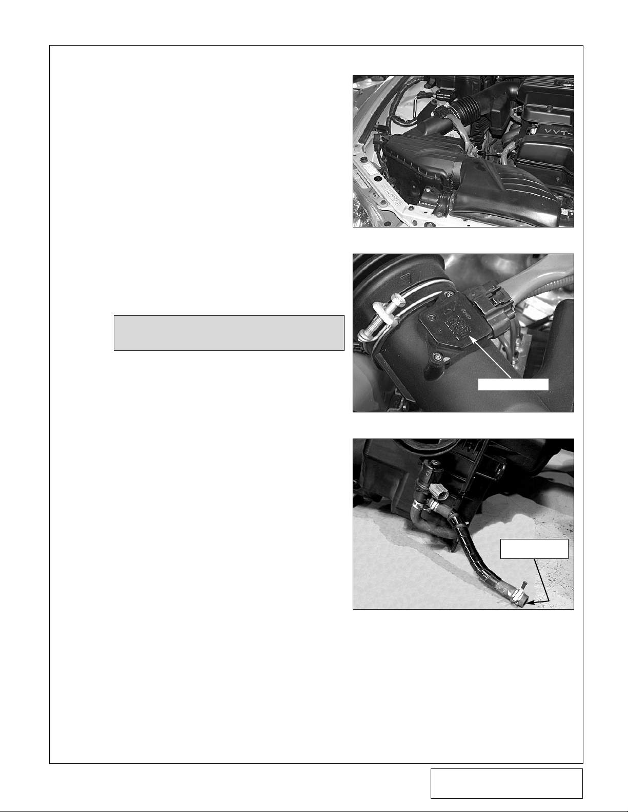
D. Using a 10mm socket and ratchet, remove
the factory air filter enclosure, air scoop, and
ducting leading to the throttle-body and set
aside. (See Fig. 1-a.)
E. Remove the MAF electronics from the previ-
ously removed intake ducting and set aside to
be reused in a later step. (See Fig. 1-b.)
F. Detach the pressure solenoid from the plastic
air filter enclosure (a single 10mm head
screw). Set solenoid and screw aside to be
reinstalled in a later section. (See Fig. 1-c.)
1. PREPARATION/REMOVAL
Fig. 1-a
Fig. 1-b
Fig. 1-c
NOTE: It is a good idea to label the line connec-
tions to prevent confusion later.
G. Disconnect the ABS module harness plug
from the module. Using a 10mm wrench,
loosen the ABS module retaining nuts.
Remove the module from its mounting bracket. Using a 12mm wrench, remove the hardware securing the ABS module bracket.
Remove the module mounting bracket from
the frame rail and set aside. Be careful not to
lose the rubber stud mounts or the rubber
bushing on the bottom of the module.
MAF ELECTRONICS
LEAVE CONNECTED
TO HARD LINE
Page 10
P/N: 4LA020-010
©2007 Vortech Engineering, LLC
All Rights Reserved, Intl. Copr. Secured
11JUL07 v1.1 Lexus(4LAv1.1)
2
H. Drain the engine coolant into a clean contain-
er and set aside. Remove the lower radiator
hose located on the passenger’s side of the
engine. Trim approximately 1" from the end of
the hose that was attached to the radiator,
and set aside. Remove the upper radiator
hose and set aside to be reinstalled in a later
step. Remove the thermostat housing. Rotate
the thermostat housing 180° and reinstall.
Disconnect the fan’s power connectors, radiator overflow bottle and remove the fan mounting hardware. Remove the engine fan assembly and set aside. Remove the upper radiator
mounts/hardware and set aside. Remove the
radiator and set aside. (See Fig. 1-d.)
I. Remove the four 5mm socket-head screws
retaining the cam sprocket cover and set the
cover and hardware aside. Locate the plastic
wire loom channel on the passenger’s side of
the engine. Remove the wire loom from the
channel. Remove the 5mm socket-head fastener securing the channel to the cylinder
head. Cut the channel as shown. (See Fig.
1-e.) Install the supplied piece of flex loom
onto the exposed section of wire and wrap
with electrical tape. Reinstall the cam sprocket cover using the factory hardware.
NOTE: Automatic transmission vehicles will
need to disconnect the cooler lines running to the radiator. Cover any open line
connections to avoid possible fluid contamination.
Fig. 1-e
Fig. 1-d
1. PREPARATION/REMOVAL, cont’d
THERMOSTAT HOUSING
ROTATED 180°
TUBE PREVIOUSLY
CONNECTED TO
PRESSURE SOLENOID
CUT LOOM HERE
Page 11
P/N: 4LA020-010
©2007 Vortech Engineering, LLC
All Rights Reserved, Intl. Copr. Secured
11JUL07 v1.1 Lexus(4LAv1.1)
3
Fig. 1-f
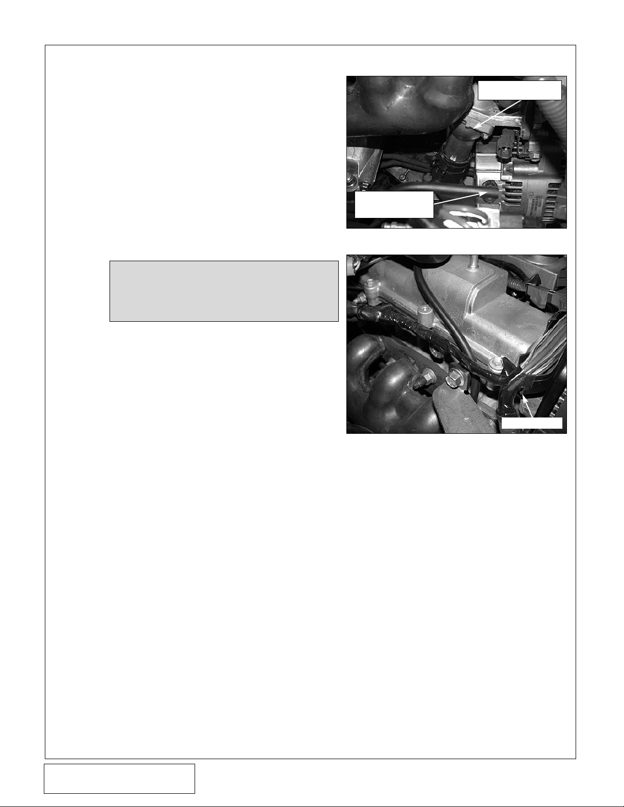
J. Remove the wire loom bracket secured to the
top of the water pump and discard. (See Fig.
1-f.) Remove the 10mm headed screw located just above and to the driver’s side of the
previously removed bracket as shown. (See
Fig. 1-g.)
K. Remove the 12mm headed bolt and wire har-
ness on the side of the water pump and discard. (See Fig. 1-g.)
L. Cut the small black cross-over tube located
just above the water pump where indicated.
(See Fig. 1-f.)
M. Loosen the four water pump pulley retainers.
Un-tension the accessory drive belt and
remove. Remove the water pump pulley
retainers and pulley, setting them aside to be
reinstalled in later step.
N. Remove the bolt securing the alternator to
the water pump. Remove the 12mm headed
bolt just to the right (driver’s side) and down
from the previously removed alternator bolt.
Remove the 10mm headed bolt just above
the alternator. (See Fig. 1-g.)
Fig. 1-g
1. PREPARATION/REMOVAL, cont’d
BOLT SECURING
LOOM BRACKET
LOWER
W/P BOLT
ALT. BOLT
REMOVE
CUT TUBE HERE
PREVIOUSLY
SECURED
LOOM
BRACKET
REMOVE
10mm HEADED
SCREW
Page 12
P/N: 4LA020-010
©2007 Vortech Engineering, LLC
All Rights Reserved, Intl. Copr. Secured
11JUL07 v1.1 Lexus(4LAv1.1)
4
A. The supercharger uses engine oil for lubrica-
tion and must have an oil feed line connected
to a filtered oil access on the engine.
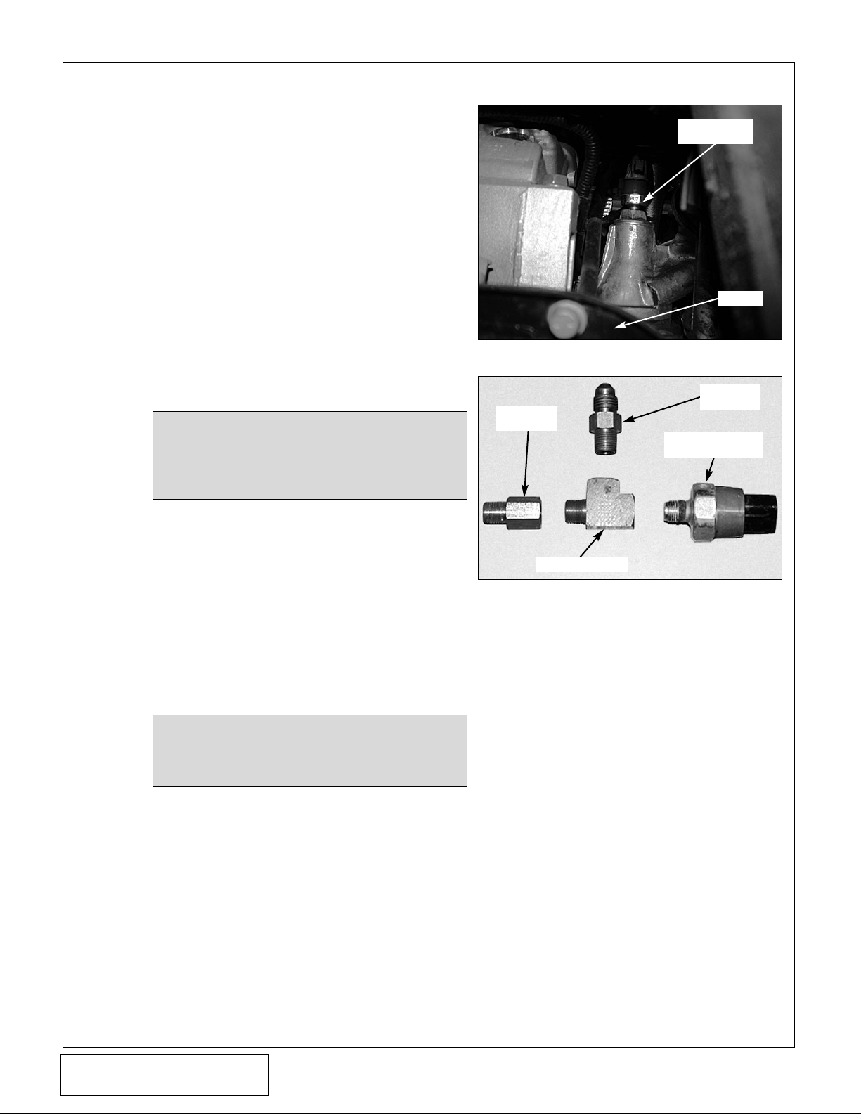
B. Locate the oil pressure sending unit on the
driver’s side of the engine, just in front of and
above the engine mount. (See Fig. 2-a.)
C. Disconnect and remove the pressure sender
and set aside to be re-installed later.
D. Locate the supplied oil feed assembly
(4LA130-026).
E. Install the supplied 1/8"BSP adapter into the
hole previously occupied by the oil pressure
sender. Install the supplied 1/8"NPT street
TEE into the BSP adapter. Orient the branch
of the TEE so that it faces up. Thread the factory sending unit into the TEE as shown.
(See Fig. 2-b.)
2. OIL FEED
Fig. 2-a (View From Below)
Fig. 2-b
OIL PRESSURE
SENDER
OIL PAN
1/8"NPT x
#4 FLARE
FACTORY OIL
PRESSURE SENDER
1/8"NPT STRT TEE
BSP
ADAPTER
NOTE: The factory wiring harness may need to
be unclipped from the engine block to
gain the necessary length to reach the
repositioned sending unit.
NOTE: Pipe tape, paste or other sealant is not
recommended as it may loosen and
cause blockage of the oil feed orifice
resulting in supercharger failure. Use
engine oil on the threads.
F. Install the supplied 1/8"NPT x #4 flare fitting
into the previously installed TEE. (See Fig.
2-b.)
G. Attach the straight end of the supplied oil feed
line to the #4 flare fitting previously installed
and route up and over the engine valve cover.
H. Temporarily cover the open oil feed line end
to keep out debris until the connection is
made to the supercharger in a later step.
I. Reconnect the factory oil pressure sender
wire.
Page 13

P/N: 4LA020-010
©2007 Vortech Engineering, LLC
All Rights Reserved, Intl. Copr. Secured
11JUL07 v1.1 Lexus(4LAv1.1)
5
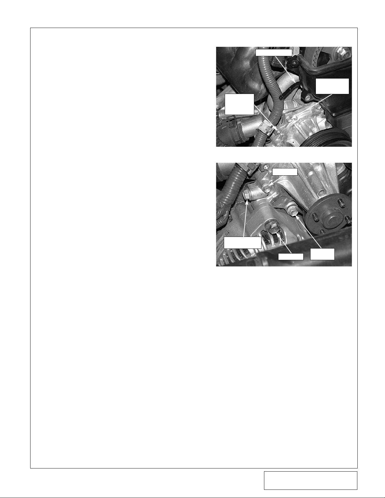
A. To provide an oil drain for the supercharger, it
is necessary to make a hole in the intermediate oil pan.
B. Locate the factory oil drain boss on the pas-
senger’s side of the engine as shown. (See
Fig. 3-a.)
C. Drill a 1/8" pilot hole into the center of the
boss. Using the supplied 9/16" rota-broach
cutter and arbor, carefully machine a throughhole into the intermediate pan.
D. Tap the previously machined hole approxi-
mately 1/4" deep using a 3/8"NPT tap. Pack
the flutes of the tap with heavy grease to hold
the chips. Thoroughly clean the threads and
hole with acetone or lacquer thinner.
E. Using a small amount of silicone sealer,
install the 3/8"NPT x 1/2" barb fitting into the
previously tapped hole. Temporarily cap the
fitting until the drain hose is connected in a
later step. (See Fig. 3-b.)
F. Drain the engine oil and change the oil filter.
3. OIL DRAIN
Fig. 3-a
Fig. 3-b
NOTE: Pack the cutter with heavy grease and
DO NOT stop the drill motor until the
rota-broach has been extracted from the
pan This will help retain the cut out piece
in the cutting tool.
NOTE: Automatic transmission vehicles only:
It may be necessary to temporarily
remove the transmission cooler lines
(see Fig. 3-a) from their mounting bracket to provide a clear path for drilling.
INTERMEDIATE
OIL PAN
OIL DRAIN LOCATION
LOWER
OIL PAN
3/8"NPT x 1/2"
BARB FITTING
INTERMEDIATE
OIL PAN
OIL PAN
ENGINE
BLOCK
Page 14

P/N: 4LA020-010
©2007 Vortech Engineering, LLC
All Rights Reserved, Intl. Copr. Secured
11JUL07 v1.1 Lexus(4LAv1.1)
6
Fig. 4-a
Fig. 4-b
Fig. 4-c
A. Locate the ABS module bracket removed in
Section 1. Remove the three spot welds that
hold the side support to the main cradle.
Separate the side support from the main cradle and discard. Drill the two lower spot weld
locations to Ø3/16" and add an annitional
Ø3/16" hole as shown. (See Fig. 4-a.)
B. (2001 Model Year Only, 2002 and Later
Skip to B-2.) —
1. Measure 2" back from the stud that previ-
ously secured the bottom of the ABS
bracket and make a mark. At the previously marked location, measure down 15/8" from the top of a frame rail and make
a second mark. Align the front and bottom
edges of the bracket where the two marks
intersect. Using the modified bracket as a
template (see Fig 4-a) to mark the three
hole locations on the frame rail. Drill the
hole locations using a 1/8" drill bit. Secure
the ABS bracket to the frame rail using
the supplied selt-tapping hardware. Cut
the factory stud that previously secured
the ABS bracket flush wiith the frame.
(See Fig. 4-b.)
(2002-2005 Model Years Only),
2. Measure 3.5" back from the stud that pre-
viously secured the bottom of the ABS
bracket and make a mark. At the previously marked location, measure down 2.4"
from the top of the frame rail and make a
second mark. Align the front and bottom
edges of the bracket where the two marks
intersect. Using the modified bracket as a
template (see Fig. 4-a) to mark the three
hole locations on the frame rail. Drill the
hole locations using a 1/8" drill. Secure the
ABS bracket to the frame rail using the
supplied self-tapping hardware. Cut the
factory stud that previoisly secured the
ABS bracket flush with the frame. (See
Fig. 4-b.)
C. Remove the 10mm headed screw that
secures the plastic brake line separator and
discard. Remove the brake lines from their
plastic separator located on the frame rail.
Slightly bend the lines running to the ABS
module so that it may be repositioned to its
new location. Secure the module to the relocated bracket using the factory hardware.
4. ABS RELOCATION
NOTE: Use caution when bending these lines.
Make bends as large as possible to
avoid kinking.
NOTE: The preferred method of removing a
spot weld is the use of a spot weld cutting tool. However in this application,
the use of an approximate sized drill or
a right-angle grinder is acceptable.
D. Locate the ABS module harness.
Carefully split the plastic flex-loom
exposing the wires from the ABS
connector to the main harness on
the shock tower. Separate enough
length to reach the relocated ABS
module and re-wrap the flex-loom.
Reconnect the harness plug to the
ABS module. (See Fig. 4-c.)
LINES SLIGHTLY BENT
RELOCATED
ABS MODULE
ABS HARNESS
SPOT WELD
NEW HOLE
LOCATION
SPOT WELDS
DRILLED
THROUGH
TOP OF FRAME RAIL
2" '01 MODEL YR
3.5" '02-'05 MODEL YRS
1-5/8" '01
MODEL YR
OF BRACKET
2.4" '02-'05
MODEL YRS
FACTORY
STUD
FRONT EDGE
OF BRACKET
BOTTOM EDGE
Page 15

P/N: 4LA020-010
©2007 Vortech Engineering, LLC
All Rights Reserved, Intl. Copr. Secured
11JUL07 v1.1 Lexus(4LAv1.1)
7
Fig. 5-b
A. Locate the S/C mounting bracket assembly
(4LA111-044.)
B. Using the M8 x 40mm socket-headed screw,
loosely attach the mounting bracket support
block (4LA010-021) to the side of the water
pump. (See Fig. 5-a.)
5. MOUNTING BRACKET AND SUPERCHARGER INSTALLATION
NOTE: For the following section, refer to Fig.
5-b for screw and spacer location. Do
not tighten until all hardware is in place.
LOWER BRACKET
SUPPORT (4LA010-021)
M8-1.25" x 40mm
(7C080-040)
Fig. 5-a
3/8-16 x 1.75" SCREW, WASHER,
& .895" SPACER (2A017-875-13)
M10-1.25 x 15mm
4LA010-010
UPPER SUPPORT
BRACKET
3/8-16 x 1" SCREW
& WASHER
3/8-16 x 2.75" SCREW, WASHER, DUST
SHIELD, 3" SPOOTH IDLER, AND IDLER
SPACER (4LA017-011)
NO SPACER/FACTORY ALT. BOLT
(M10-1.25 x 50mm)
3/8-16 x 1" SCREW,
WASHER, NYLOC NUT
Ø.50" x 1.538" SPACER
(2A017-501-153)
M6-1.0 x 70mm
SCREW & WASHER
M6-1.0 x 70mm
SCREW & WASHER
SPACER, LOWER
SUPPORT
(4LA010-021)
Ø.875" x 1.437" SPACER
M8-1.25 x 80mm
SCREW & WASHER
Page 16

P/N: 4LA020-010
©2007 Vortech Engineering, LLC
All Rights Reserved, Intl. Copr. Secured
11JUL07 v1.1 Lexus(4LAv1.1)
8
C. Using Fig. 5-b as a guide and working from
the bottom up, install all the applicable hardware and spacers into position as follows:
1. With the mounting bracket in position,
place the M8-1.25 x 80mm screw and
washer through the mounting bracket,
1.437" spacer and into the lower water
pump mounting hole.
2. Then install the factory alternator bolt
(M10-1.25 x 50mm) through the mounting
bracket and into the alternator mount.
3. Next, install the M6-1.0 x 70mm screw
and washer through the mounting bracket
support spacer (4LA010-021) and into the
water pump.
4. Install the 3/8-16 x 2.75" screw and wash-
er through the dust shield, Ø3" smooth
idler, idler spacer, and into the support
spacer (4LA010-021).
5. Install the 3/8-16 x 1" screw and washer
through the mounting bracket and into the
support spacer (4LA010-021).
6. Install the M6-1.0 x 70mm screw and
washer through the mounting bracket,
1.538" long spacer and into the upper
water pump location.
7. Tighten the previously installed hardware.
Make sure all mounting surfaces seat flat
against one another and no lines or wire,
etc. are being pinched.
D. Loosely install the upper support bracket
(4LA010-010) to the S/C bracket using the
two 3/8-16 x 1.0" screws, washers and
Nylock nuts. Install the M10-1.25 x 16mm
screw through the support bracket and into
the cylinder head. (See Fig. 5-c.)
E. Evenly tighten the previously installed hard-
ware. Ensure the bracket is supported, but
not pulled or the location of the S/C bracket is
not changed.
F. Remove the blue plastic dust cap located on
the 1/2" oil drain fitting at the bottom of the
supercharger. Attach the supplied 1/2" fabric
braided oil drain hose to the supercharger
drain fitting. Secure with a #8 hose clamp.
G. Secure the supercharger to the main bracket
using the five 3/8-16 x 1.75" screws, washers,
and .896" long spacers. (See Fig. 5-b, 5-c.)
H. Reinstall the factory water pump pulley and
secure using the factory hardware.
5. MOUNTING BRACKET AND SUPERCHARGER INSTALLATION, cont’d
Fig. 5-c
UPPER SUPPORT
BRACKET
M10-1.25 x
15mm SCREW
.895" LONG
SPACER
SEPARATE MAF HARNESS HERE
Page 17

P/N: 4LA020-010
©2007 Vortech Engineering, LLC
All Rights Reserved, Intl. Copr. Secured
11JUL07 v1.1 Lexus(4LAv1.1)
9
5. MOUNTING BRACKET AND SUPERCHARGER INSTALLATION, cont’d
I. Install a 12mm-1.75 x 40mm screw through
the dust shield, Ø3" smooth idler, idler spacer
(.462" long piloted), and into the middle
supercharger mounting boss. (See Fig. 5-d.)
J. Remove the blue plastic dust cap located on
the brass oil feed nozzle on the side of the
supercharger. Thread the supplied 1/8"NPT x
90° fitting into the oil feed nozzle. Carefully
tighten and clock the fitting as shown. (See
Fig.5-e.) Use caution when tightening the oil
feed fitting, as the nozzle may break if care is
not exercised. Connect the previously
installed oil feed line to the 90° fitting as
shown. (See Fig. 5-e.)
K. Install the supplied drive belt as shown. (See
Fig. 5-f.)
Fig. 5-d
Fig. 5-e
Fig. 5-f
3" SMOOTH IDLER
IN MIDDLE POSITION
90° END OF SUPPLIED OIL LINE
1/8"NPT x 90°
NOTE: Use clean engine oil to lubricate fitting
threads. Pipe tape, paste, or other types
of sealant are not recommended as it
might loosen and cause blockage of the
oil feed orifice, resulting in supercharger
failure.
SUPERCHARGER
IDLER
IDLER
WATER
PUMP
TENS.
POWER
STEERING
ALT.
CRANK
A/C
Page 18

P/N: 4LA020-010
©2007 Vortech Engineering, LLC
All Rights Reserved, Intl. Copr. Secured
11JUL07 v1.1 Lexus(4LAv1.1)
10
6. CHARGE COOLER INSTALLATION
Fig. 6-a
Fig. 6-b
Fig. 6-c
A. Locate the discharge assembly 8N201-330.
Use Fig. 6-a as reference.
B. Remove the 10mm headed screws securing
the plastic splash shield to the bottom of the
car and set aside.
C. Using a Ø2.5 x 25° sleeve and #40 clamps
provided, secure Tube “A” onto the supercharger discharge. (See Figs. 6-a, 6-b.)
D. Secure the supplied bypass valve to Tube “A”
using the Ø1" x 90° elbow and two #16 hose
clamps provided. Orient as seen in Fig.
6-b and install the supplied 1"ID filter. Attach
a length of Ø5/32" vacuum hose to the
bypass valve and route to the vacuum port on
the intake manifold. Remove the factory vacuum cap from the manifold port and attach the
previously routed vacuum line. (See Fig. 6-c.)
TUBE “A”
TUBE “B”
TUBE “E”
TUBE “D”
CHARGE COOLER
TUBE “C”
Ø2.5" x 25° SLEEVE
BYPASS VALVE
TUBE “A”
VACUUM LINE
TO BYPASS
VALVE
VACUUM PORT
Page 19

P/N: 4LA020-010
©2007 Vortech Engineering, LLC
All Rights Reserved, Intl. Copr. Secured
11JUL07 v1.1 Lexus(4LAv1.1)
11
6. CHARGE COOLER INSTALLATION, cont’d
Fig. 6-e
Fig. 6-f
Fig. 6-d
TUBE “B”
TUBE “C”
Ø2.5" x 25°
SLEEVE
Ø4.5" HOLE IN
SPLASH PANEL
Ø2.5" x 25°
SLEEVE
CAC
CAC
TUBE “C”
Ø2.5 x 25°
SLEEVE
E. Attach Tube “B” using a Ø2.5" x 25° sleeve
and #40 clamps provided to Tube “A” as
shown. (See Fig. 6-d.)
F. A Ø4.5" hole will need to be cut in the driver’s
side splash panel to provide a path for the
CAC discharge tube. Using a Ø4.5" hole saw
or tool of choice, mark and drill the hole location shown. (See Fig. 6-e.)
Ø2.5" x 25° SLEEVE
TUBE “B”
OIL PAN
Page 20

P/N: 4LA020-010
©2007 Vortech Engineering, LLC
All Rights Reserved, Intl. Copr. Secured
11JUL07 v1.1 Lexus(4LAv1.1)
12
POWER STEERING COOLER PREVIOUSLY
ATTACHED TO CORE SUPPORT
ECU ENCLOSURE
10mm HEADED
SCREW
LINE BRACKET
CUT HERE
6. CHARGE COOLER INSTALLATION, cont’d
Fig. 6-g
Fig. 6-h
Fig. 6-i
G. Remove the three retaining screws at the top
of the grill. Unclip the bottom edge of the grill.
Remove the grill and set aside.
H. Locate and remove the two 10mm headed
screws that secure the P/S cooler to the front
core support. Disconnect the rubber P/S
hoses from the steel P/S line assembly located near the P/S reservoir. Remove the power
steering cooler and the steel P/S line assembly located on the driver’s side of the radiator
and discard. (See Fig. 6-g.) To gain access
to the assembly on the driver’s side, you will
first need to temporarily remove the three
10mm headed retaining screws that secure
the ECU enclosure and pull the enclosure
upward to gain access to the 10mm headed
screw that retains the line bracket to the top
of the frame rail. Once you remove the line
bracket, re-secure the ECU enclosure using
the factory hardware. (See Fig. 6-h.)
NOTE: Leave the rubber lines connected to the
power steering pump.
I. Remove the two retainers securing the top of
the A/C condenser. Tilt the condenser back
toward the engine (be careful not to damage
the condenser).
J. Remove the bolt securing the hood latch
assembly to the core support. Cut approximately 9" from the bottom of this mount.
(See Fig. 6-i.)
Page 21

P/N: 4LA020-010
©2007 Vortech Engineering, LLC
All Rights Reserved, Intl. Copr. Secured
11JUL07 v1.1 Lexus(4LAv1.1)
13
6. CHARGE COOLER INSTALLATION, cont’d
Fig. 6-j
Fig. 6-k
Fig. 6-l
CAC MOUNTING BRACKET
8N010-210
FACTORY HARDWARE
K. Secure the CAC (Charge Air Cooler) bracket
8N010-210 to the passenger’s side frame rail
using the factory hardware as shown. (See
Fig. 6-j.) Loosely install the charge cooler into
its location. (See Figs. 6-j,6-k.)
L. Using the supplied 1/4-20 x .50 " hardware,
loosely attach the CAC to the mounting
bracket.
M. Reinstall the A/C condenser, and secure
using the factory hardware.
N. Install one of the provided Ø2.5-25° sleeves
onto the CAC inlet and secure using #40
hose clamps. (See Fig. 6-e.)
O. Using a Ø2.5" x 25° sleeve and #40 clamps
provided, secure Tube “C” to the open end of
Tube “B” and the 25° sleeve previously
installed onto the CAC. (See Figs. 6-e, 6-f.)
P. To provide a path for the discharge ducting,
you must cut a Ø3" hole through the inner
fender behind the passenger’s side headlight.
Using the provided template, mark and drill
the location. Take care not to damage the
headlight assembly or wiring harnesses in
this area. (See Fig. 6-l, 6-m.)
Q. Install one of the Ø2.5" x 25° elbow onto the
CAC discharge (passenger’s side outlet) and
secure using the provided #40 hose clamp.
(See Fig. 6-m.)
Page 22

P/N: 4LA020-010
©2007 Vortech Engineering, LLC
All Rights Reserved, Intl. Copr. Secured
11JUL07 v1.1 Lexus(4LAv1.1)
14
This Page Left Intentionally Blank
Page 23

P/N: 4LA020-010
©2007 Vortech Engineering, LLC
All Rights Reserved, Intl. Copr. Secured
11JUL07 v1.1 Lexus(4LAv1.1)
15
Template
Page 24

P/N: 4LA020-010
©2007 Vortech Engineering, LLC
All Rights Reserved, Intl. Copr. Secured
11JUL07 v1.1 Lexus(4LAv1.1)
16
This Page Left Intentionally Blank
Page 25

P/N: 4LA020-010
©2007 Vortech Engineering, LLC
All Rights Reserved, Intl. Copr. Secured
11JUL07 v1.1 Lexus(4LAv1.1)
17
6. CHARGE COOLER INSTALLATION, cont’d
Fig. 6-m
Fig. 6-n
Fig. 6-o
TUBE “D”
Ø2.5" x 25°
ELBOW
TUBE “A”
TUBE “B”
2.75"-3" REDUCER SLEEVE
TUBE “E”
MAF ELECTRONICS
R. Install the straight section of discharge duct
“D” up through the previously cut Ø3" hole.
Attach the curved end to the previously
installed elbow and secure using the provided
#40 hose clamp. (See Fig. 6-m.)
S. Install one of the provided Ø3" x Ø2.75"
reducer sleeve onto the open end of duct “D”
and secure using the provided #40 clamps.
T. Secure the remaining Ø3" x Ø2.75" reducer
sleeve to the throttle body using the supplied
#40 hose clamp. (See Fig. 6-n.)
U. Secure the previously removed MAF electron-
ics to Tube “E” using the supplied 8-32 x .50"
hardware. (See Fig. 6-o.) Make sure the
OEM O-ring is in place and is undamaged.
NOTE: Rotate the previously installed 25°
elbow to allow best tube engagement
and core support clearance.
Page 26

P/N: 4LA020-010
©2007 Vortech Engineering, LLC
All Rights Reserved, Intl. Copr. Secured
11JUL07 v1.1 Lexus(4LAv1.1)
18
Fig. 6-p
6. CHARGE COOLER INSTALLATION, cont’d
V. Connect the previously installed sleeves
using discharge duct “E” and two #44 hose
clamps. (See Fig. 6-p.)
W. Locate the factory MAF harness. Carefully
split the plastic flex-loom exposing the wire to
the sensor connector. Separate enough
length to reach the new MAF sensor location,
and re-wrap the flex-loom. Reconnect the
harness plug to the MAF sensor.
TUBE “E”
Ø3" x Ø2.75"
REDUCER
Ø3" x Ø2.75"
REDUCER
Page 27

P/N: 4LA020-010
©2007 Vortech Engineering, LLC
All Rights Reserved, Intl. Copr. Secured
11JUL07 v1.1 Lexus(4LAv1.1)
19
Fig. 7-c
A. Locate the 4LA112-010 Air Inlet Assembly.
B. Loosely install the supplied air filter onto the
supercharger inlet. Mark the two hole locations to be drilled in the filter. One hole
approximately Ø5/16" in the center of the filter. The other hole should be approximately
Ø1/2" and offset to clear the ABS lines. (See
Fig. 7-a.)
7. AIR INLET INSTALLATION
Fig. 7-b
Fig. 7-a
SUPPLIED AIR FILTER
1/2" UNION
5/16" 90° ELBOW
LINE TO PRESSURE SOLENOID
LINE TO MOLDED FACTORY HOSE
PRESSURE
SOLENOID
LINE TO FILTER
MOLDED FACTORY HOSE
5/16" HOSE
MENDER
5/16" HOSE TO
PRESSURE
SOLENOID
RELOCATED
ABS MODULE
C. Install the two fittings into the end of the air
filter and re-install onto the supercharger inlet
and secure. (See Fig. 7-a.)
D. Locate the pressure solenoid removed from
the plastic air filter enclosure in a previous
step.
E. Secure the solenoid to the top of the passen-
ger’s side frame rail using the factory retainer
as shown. (See Fig. 7-b.)
F. Using the supplied union and length of
Ø5/16" hose provided, connect the formed
rubber hose (previously connected between
the filter enclosure and the solenoid) to the
vacuum port as shown. (See Figs. 7-b, 7-c.)
G. Connect the remaining portion of the Ø5/16"
hose between the Ø5/16" x 90° fitting previously installed into the air filter and open vacuum port on the pressure solenoid. (See
Figs. 7-a, 7-b.)
NOTE: Thoroughly clean the inside of the filter
and inspect to make sure no material is
left from the drilling process.
Page 28

P/N: 4LA020-010
©2007 Vortech Engineering, LLC
All Rights Reserved, Intl. Copr. Secured
11JUL07 v1.1 Lexus(4LAv1.1)
20
Fig. 7-g
7. AIR INLET INSTALLATION, cont’d
VALVE COVER BREATHER
1/2" UNION
1/2" HOSE
1/2" UNION
H. Using the supplied union and length of Ø1/2"
hose provided, connect the valve cover
breather hose (previously connected to the
factory air box) to the union previously
installed in the supplied air filter. (See Figs.
7-a, 7-g.)
I. Attach the length of Ø5/32" vacuum hose to
the bypass valve and route to the vacuum
port on the intake manifold. Remove the factory vacuum cap from the manifold port and
attach the previously routed vacuum line.
Page 29

P/N: 4LA020-010
©2007 Vortech Engineering, LLC
All Rights Reserved, Intl. Copr. Secured
11JUL07 v1.1 Lexus(4LAv1.1)
21
8.1 FUEL MANAGEMENT UNIT (FMU) RECALIBRATION (2003 Auto)
NOTE: This step applies to Model Year 2003 automatic vehicles only! For all
others, skip the following and proceed with Section 8.2.
A. Remove the six allen-head screws on top of
the fuel management unit (FMU).
B. Remove the diaphragm and 8:1 disk and
ring from inside of the FMU.
WARNING: Do not remove the four
screws holding the valve
body. Once taken apart,
the valve would have to
be replaced.
C. Install the replacement 10:1 ring (with
the notched part facing FMU body)
around the four screws inside the FMU.
(The 10:1 components are larger in
diameter than the 8:1).
D. Place the 10:1 disk inside the ring next to the
piston.
E. Install the new diaphragm and carefully line
up the holes to the body.
F. Place the spring retainer in the center of the
diaphragm with the spring between it and the
cover. (See Fig. 8.1-a.)
G. Reinstall the FMU cover with the six allen-
head screws. Do not over-tighten the screws.
The correct torque is 24 in/lb (2ft/lb).
8:1 RING SPACER
8:1 WASHER (Ø2.270")
LARGE DIAPHRAM
SPRING RETAINER
SPRING
FCU COVER
Fig. 8.1-a
Page 30

P/N: 4LA020-010
©2007 Vortech Engineering, LLC
All Rights Reserved, Intl. Copr. Secured
11JUL07 v1.1 Lexus(4LAv1.1)
22
This Page Left Intentionally Blank
Page 31

P/N: 4LA020-010
©2007 Vortech Engineering, LLC
All Rights Reserved, Intl. Copr. Secured
11JUL07 v1.1 Lexus(4LAv1.1)
23
Fig. 8-a
A. Locate the rubber section of the fuel supply
line on the driver’s side frame rail as shown.
(See Fig. 8-a.)
B. Cut the fuel line in approximately the middle
of its length. (See Figs. 8-a, 8-b.)
C. Using the FMU and mounting bracket as a
template, position the FMU as shown. (See
Fig. 8-c.) Mark the two hole locations. Drill
1/8" pilot holes in the previously marked hole
locations. Install the FMU using the provided
#12 sheet-metal screws as shown. (See Fig.
8-c.) Cut the spring lock fittings off of the supplied FMU lines as close to the fitting as possible and discard.
D. Position the supplied fuel pump as shown.
(See Fig. 8-d.) Mark and drill the two pilot
holes in the sub-frame support brace. Secure
the fuel pump and fuel pump ground wire to
the sub-frame support brace using the supplied adel clamps and #12 sheet metal
screws. (See Fig. 8-d.)
E. (See Figs. 8-e, 8-f for reference.)
1. Attach the two supplied Ø5/16" hose barb
TEEs to the open ends of the previously
cut factory fuel line.
2. Connect the hose from the FMU inlet port
on the previously installed FMU to the
TEE connected to the line from the fuel
tank. Connect a length of supplied hose
from the branch of the same TEE to the
fuel pump inlet port.
3. Connect the length of hose from the out-
let on the side of the FMU to the TEE
attached to the line going to the fuel rail
on the manifold. Connect a length of supplied hose from the branch of the same
TEE to the fuel pump outlet.
NOTE; The following step should be completed in a
well ventilated area free of any ignition source.
NOTE; Spring lock fittings are not used in this
application
NOTE; When installing the fuel lines in this step,
install the supplied clamps simultaneously. However, do not clamp until all connections have been made and verified.
NOTE; Using a pair of locking pliers to pinch the
fuel line on the fuel tank side of your cut
location to avoid draining the fuel tank.
Use caution as there will be fuel drainage
from the engine side of the cut.
Fig. 8-b
Fig. 8-c
Fig. 8-d
8.2 FUEL PUMP AND FMU INSTALLATION
TRANSMISSION
DRIVER’S SIDE
FRAME RAIL
STEERING
LINKAGE
FUEL LINE TO BE CUT
FMU
FMU MOUNTING BRACKET
SUPPLIED FUEL PUMP
1-11/16" ADEL CLAMPS
FUEL LINE FROM TANK
FLOW
GROUND WIRE
Page 32

P/N: 4LA020-010
©2007 Vortech Engineering, LLC
All Rights Reserved, Intl. Copr. Secured
11JUL07 v1.1 Lexus(4LAv1.1)
24
4. Verify that all line connections have been
made properly. Adjust all previously
installed hoses and fittings so the lines
route smoothly and are kept away from
any sharp or moving parts. Tighten
securely, all previously installed clamps at
this time.
5. Connect the supplied length of Ø5/32"
vacuum line to the pressure port on the
FMU. Route the line up underneath the
intake manifold to the vacuum port on the
intake manifold. Using the supplied
Ø5/32" vacuum TEE, connect the line to
the previously installed line going to the
by-pass valve. (See Fig. 8-g.)
Fig. 8-e
8.2 FUEL PUMP AND FMU INSTALLATION, cont’d
Fig. 8-f
Fig. 8-g
VACUUM LINE
TO BYPASS
VALVE
VACUUM PORT
FACTORY FUEL LINE
TO INTAKE MANIFOLD
5/32" HOSE (CONNECTED
TO MANIFOLD PRESSURE)
INLET
FACTORY SUPPLY
LINE FROM FUEL
TANK
OUTLET
INSTALL AND TIGHTEN CLAMPS
USING STEPLESS
CLAMP PLIERS
INSTALL THE SUPPLIED SHEET-METAL SCREWS TO
HOLD THE FUEL MANAGEMENT UNIT AND FUEL PUMP
MARK AND DRILL HOLES
5/16" HOSE
BARB TEES
SUPPLIED
FUEL PUMP
RED POWER WIRE
(FROM FUEL PUMP RELAY)
WASHERS ARE INSTALLED
AND FITTINGS ARE TIGHT)
(VERIFY THAT COPPER
Page 33

P/N: 4LA020-010
©2007 Vortech Engineering, LLC
All Rights Reserved, Intl. Copr. Secured
11JUL07 v1.1 Lexus(4LAv1.1)
25
F. Mount the supplied fuel pump relay as seen
in Fig. 8-h using factory hardware. Using one
of the supplied ring-terminals, connect the
provided fuse holder to the (+) battery terminal. Connect terminals #85 and #30 to the
fuse holder previously connected to the battery. Route the long black wire from terminal
#87 to the postive (+) terminal on the previously installed fuel pump. Terminal #86 will be
connected in a later step. (See Fig. 8-i
“RELAY WIRING SCHEMATIC” for correct
wiring.)
Fig. 8-h
Fig. 8-i
8.2 FUEL PUMP AND FMU INSTALLATION, cont’d
(+) TERMINAL ON
SUPPLIED FUEL PUMP
87
CONTROL
BOX
87a
30
8586
RELAY WIRING SCHEMATIC
(+) BATTERY
TERMINAL
Page 34

P/N: 4LA020-010
©2007 Vortech Engineering, LLC
All Rights Reserved, Intl. Copr. Secured
11JUL07 v1.1 Lexus(4LAv1.1)
26
A. Locate the power steering cooler relocation
assembly (4LA110-010). (See Fig. 9-a.)
B. Attach the supplied Ø5/16" rubber hoses to
the power steering cooler and secure using
the stepless clamps provided.
C. Secure the power steering cooler to the A/C
condenser using the supplied nylon mounting
kit. (See Fig. 9-b.)
D. Route the hoses around the driver’s side of
the radiator and towards the factory P/S
hoses.
E. Using the supplied Ø3/8" to Ø5/16" barbed
reducers, two factory clamps and two stepless clamps provided, connect and secure the
rubber lines to the factory P/S hoses. (See
Fig. 9-c.)
F. Top off the power steering system reservoir
using the factory recommended power steering fluid.
G. Using the factory hardware, reinstall the radi-
ator and fan assembly. Install the upper and
modified lower factory radiator hoses and
secure using the original clamps. Refill the
engine coolant system using the coolant
drained in a previous step (provided it is in
good condition). Automatic transmission vehicles reconnect the factory transmissiion cooler lines, you will need to wait until the installtion is complete before checking fluid level.
9. POWER STEERING
Fig. 9-a
Fig. 9-b
Fig. 9-c
Page 35

P/N: 4LA020-010
©2007 Vortech Engineering, LLC
All Rights Reserved, Intl. Copr. Secured
11JUL07 v1.1 Lexus(4LAv1.1)
27
A. Locate the factory ECU enclosure. Using a
10mm socket, remove the three retaining
screws. Set the enclosure cover and hardware aside to be reinstalled later. (See Fig.
10-a.)
B. Disconnect the ECU harness connectors
located next to the ECU. To make room for
the supplied ECU interface, you will need to
remove the plastic connector cradle and discard. (See Fig. 10-b.) Reconnect the harness
connectors. (See Fig. 10-c.)
C. Locate the supplied plug and play harness
connection. (See Fig. 10-d.) Make the appliicable ECU connections. Each connector plug
is different from the others so there is only
one possible location for each. (See Fig.
10-e.)
10. ELECTRONIC CONTROL BOX INSTALLATION
Fig. 10-a
Fig. 10-b
Fig. 10-c
Fig. 10-d
ECU ENCLOSURE
10mm HEADED
RETAINING SCREWS
HARNESS CONNECTOR
PLASTIC CRADLE
PLUG & PLAY
HARNESS CONNECTION
Page 36

P/N: 4LA020-010
©2007 Vortech Engineering, LLC
All Rights Reserved, Intl. Copr. Secured
11JUL07 v1.1 Lexus(4LAv1.1)
28
D. Once the connections have been made, gen-
tly push the unit down into the factory ECU
housing next to the ECU. (See Fig.10-e.)
E. Locate the factory ECU cover previously
removed and cut a hole approximately Ø1/2"
in the cover to allow the small 24-pin connector harness to pass through. Install the 24-pin
connector harness through the ECU cover.
Reinstall the ECU cover using the factory
hardware. Using the supplied Velcro installation strip, install the control module to the
ECU cover. (See Figs. 10-f, 10-g.)
F. Connect the 16-pin and 24-pin connectors to
the control module. Install the provided ring
terminal onto the brown wires on the 16-pin
harness. Route the brown wire to the location
shown (see Fig. 10-f) and ground to chassis.
Route the red and white wire to the fuel pump
relay previously installed and connect to terminal #86 as shown previously in the “RELAY
WIRING SCHEMATIC”. (See Fig. 8-i.on
page 23)
10. ELECTRONIC CONTROL BOX INSTALLATIION. cont’d
Fig. 10-e
Fig. 10-f
Fig. 10-g
FACTORY ECU
SUPPLIED PLUG &
PLAY HARNESS
CONTROL
MODULE
16-PIN
CONNECTOR
24-PIN
CONNECTOR
BROWN
GROUND WIRE
FUEL PUMP
TRIGGER WIRE
Page 37

P/N: 4LA020-010
©2007 Vortech Engineering, LLC
All Rights Reserved, Intl. Copr. Secured
11JUL07 v1.1 Lexus(4LAv1.1)
29
Fig. 11-a
A. Reconnect the battery.
B. If your vehicle has gone over 20,000 miles
since its last spark plug change, you will need
to change the spark plugs now before test
driving the vehicle.
C. Check all fittings, nuts, bolts and clamps for
tightness. Pay particular attention to oil and
fuel lines around moving parts, sharp edges
and exhaust system parts. Make sure all
wires and lines are properly secured with
clamps or tie-wraps. (See Fig. 11-a.)
D. Check all fluid levels, making sure that your
tank(s) is/are filled with 91 octane or higher
fuel before commencing test drive.
E. Start engine and allow to idle a few minutes,
then shut off.
F. Recheck to be sure that no hoses, wires, etc.
are near exhaust headers or moving parts
and for signs of any fluid leakage.
G. PLEASE TAKE SPECIAL NOTE: Operating
the vehicle without ALL the subassemblies
completely and properly installed may cause
FAILURE OF MAJOR COMPONENTS.
H. Recheck all fluid levels following the factory
recommended procedures at this time.
I. Test drive the vehicle by gradually working up
to full throttle and paying close attention to
any abnormal sounds or engine detonation. If
detonation is heard, discontinue heavy throttle usage until the necessary adjustment or
repairs are made.
J. Read the Street Supercharger System
Owner's Manual and RETURN THE
WARRANTY REGISTRATION FORM within
thirty (30) days of purchasing your super-
charger system to qualify.
11. FINAL CHECK
WARNING: Due to variances in each vehicle,
Vortech recommends that the vehicle
get a “custom tune” from a local, reputable tuner.
This kit is supplied with a “universal”
fuel and ignition timing calibration. This
calibration is intended to allow the vehicle to start and operate at part throttle,
and is not optimized for full throttle
performance. Do not operate the vehicle
at heavy throttle or high RPM until a
custom calibration tailored for your
specific vehicle can be obtained from a
competent tuner. A “wide-band”
exhaust oxygen sensor must be used to
confirm proper air/fuel ratio. Vortech
suggests a proper WOT air/fuel ratio
range of 10.8-11.0:1 for 91 octane fuel.
WARNING: Never operate your engine at full
throttle when the engine is cold.
Always allow plenty of time for the oil
to reach full operating temperature
before running above 2,500 RPM. Full
supercharger operating temperature is
generally achieved only after the
engine water temperature has been at
the normal indicated operating range
for two or three minutes.
Page 38

DP/N: 4LA020-010 - v1.1 07/10/07
®
1650 Pacific Avenue, Channel Islands CA 93033-9901 • Phone: 805 247-0226
Fax: 805 247-0669 • www.vortechsuperchargers.com • M-F 8:00AM - 4:30PM (PST)
ENGINEERING, LLC
 Loading...