

Page 1
Ford 4.6L 1999-2001 DOHC
®
Mustang Cobra/2003-2004 Mach 1
Supercharger System
1999 MODEL YEAR -
2001-2003 MODEL YEAR -
Installation Instructions
50 State Smog Legal per CARB EO #D-213-17
50 State Smog Legal per CARB EO #D-213-20
* 2004 Model Year
* 2004 Models legal in California only for racing vehicles which may never be used upon a highway
1650 PACIFIC AVENUE • CHANNEL ISLANDS, CA 93033-9901 • (805) 247-0226
FAX (805) 247-0669 • www.vortechsuperchargers.com • M-F 8:00 AM - 4:30 PM PST
P/N: 4FR020-010
©2004 Vortech Engineering, LLC
All Rights Reserved, Intl. Copr. Secured
23AUG04 86-93 4V Mus. Cobra(4FR v3.1)
.
ENGINEERING, LLC
Page 2

P/N: 4FR020-010
©2004 Vortech Engineering, LLC
All Rights Reserved, Intl. Copr. Secured
23AUG04 86-93 4V Mus. Cobra(4FR v3.1)
FOREWORD
Proper installation of this supercharger kit requires general automotive
mechanic knowledge and experience. Please browse through each step
of this instruction manual prior to beginning the installation to determine if
you should refer the job to a professional installer/technician. Please call
Vortech Engineering for possible installers in your area.
P/N: 4FR020-010
©2004 Vortech Engineering, LLC
All Rights Reserved, Intl. Copr. Secured
23AUG04 86-93 4V Mus. Cobra(4FR v3.1)
© 2004 VORTECH ENGINEERING, LLC
All rights reserved. No part of this publication may be reproduced, transmitted, transcribed, or
translated into another language in any form, by any means without written permission of
Vortech Engineering, LLC.
ii
Page 3

TABLE OF CONTENTS
FOREWORD .......................................................................................................................ii
TABLE OF CONTENTS ......................................................................................................iii
IMPORTANT NOTES ..........................................................................................................iv
TOOLS AND SUPPLY REQUIREMENTS...........................................................................v
PARTS LIST - 1999 4.6L DOHC MUSTANG.......................................................................vi
PARTS LIST - 1999 4.6L DOHC MUSTANG w/AFTERCOOLER .......................................vii
PARTS LIST - 2001 4.6L DOHC MUSTANG.......................................................................viii
PARTS LIST - 2001 4.6L DOHC MUSTANG w/AFTERCOOLER .......................................ix
PARTS LIST - 2003-2004 4.6L DOHC MACH 1..................................................................x
PARTS LIST - 2003-2004 4.6L DOHC MACH 1 w/AFTERCOOLER ..................................xi
1. PREPARATION/REMOVAL......................................................................................1
2. OIL DRAIN ...............................................................................................................2
3. OIL FEED.................................................................................................................3
4. FUEL PUMP INSTALLATION...................................................................................3
5. FUEL INJECTOR REPLACEMENT .........................................................................4
6. AIR CONDITIONING LINE MODIFICATION............................................................5
7. FAN RESISTOR RELOCATION (2001 Cobra and 2003-2004 Mach 1 Only) ..........5
8. MAIN BRACKET ASSEMBLY/DRIVE BELT.............................................................6
8.1 MAIN BRACKET ASSEMBLY/DRIVE BELT (1999 0nly)..........................................7
8.2 MAIN BRACKET ASSEMBLY/DRIVE BELT (2001 Cobra and 2003-2004
Mach 1 0nly) ............................................................................................................11
9. RADIATOR HOSE/WATER TUBE............................................................................18
10. AIR INLET................................................................................................................20
11. SUPERCHARGER DISCHARGE ............................................................................27
12. ECM MODULE INSTALLATION...............................................................................28
13. FINAL CHECK .........................................................................................................29
©2004 Vortech Engineering, LLC
iii
All Rights Reserved, Intl. Copr. Secured
23AUG04 86-93 4V Mus. Cobra(4FR v3.1)
P/N: 4FR020-010
Page 4

P/N: 4FR020-010
©2004 Vortech Engineering, LLC
All Rights Reserved, Intl. Copr. Secured
23AUG04 86-93 4V Mus. Cobra(4FR v3.1)
1999-2004 4.6L DOHC Cobra/Mach
1 Mustang
IMPORTANT NOTES
This kit requires ECM modication and the installation of a Vortech ECM
Module. The modules are made specically for each individual vehicle
with respect to the factory ECM calibration. The ECM must be sent
directly to Vortech by the installing customer (the charge for this service
with module installation has been included in the purchase price).
•Included in this kit is a prepaid next-day air shipping box and a credit tag for
one Vortech ECM Module.
• Simply contact the Vortech Service Department at (805) 247-0226 to request a
Return Authorization Number (See ECM Module Credit Tag for more details).
- Mail the enclosed "ECM Module Credit Tag" (send original tag - no photocopies
will be accepted) and ECM to Vortech in the supplied box.
- Turnaround time will be 1-2 days (each application varies). Vortech will give an
estimate at the time of your order.
Your Vortech ECM Module comes with a twelve month limited warranty from the
original date of purchase of your supercharger system (see owner's manual for
details).
OFF-HIGHWAY USE:
When driving vehicle on non-public roads (off-road applications such
as racing/high rpm) Vortech strongly recommends replacing the factory
platinum plugs with NGK #4177 or Denso IT20 and reducing the factory
spark plug gap down to .032".
This product is protected by state common law, copyright and/or patent.
All legal rights therein are reserved. The design, layout, dimensions,
geometry, and engineering features shown in this product are the
exclusive property of Vortech Engineering, LLC. This product may not
be copied or duplicated in whole or part, abstractly or fundamentally,
intentionally or fortuitously, nor shall any design, dimension, or other
information be incorporated into any product or apparatus without prior
written consent of Vortech Engineering, LLC.
P/N: 4FR020-010
©2004 Vortech Engineering, LLC
All Rights Reserved, Intl. Copr. Secured
23AUG04 86-93 4V Mus. Cobra(4FR v3.1)
iv
Page 5
1999-2004
FORD 4.6L DOHC COBRA/MACH 1 MUSTANG
Installation Instructions
CARB E0 #D-213-17 / CARB E0 #D-213-20 (Except 2004 Models)
Congratulations on selecting the best performing and best backed automotive
supercharger available today... the VORTECH® V-2® supercharger!
Before beginning this installation, please read through this entire instruction booklet and the Street
Supercharger System Owner's Manual which includes the Limited Warranty Program and the Warranty
Registration form.
Vortech supercharger systems are performance improving devices. In most cases, increases in torque of 30 - 35%
and horsepower between 35 - 45% can be expected with the boost levels specied by Vortech Engineering. This
product is intended for use on healthy, well maintained engines. Installation on a worn-out or damaged engine is
not recommended and may result in failure of the engine as well as the supercharger. Vortech Engineering is
not responsible for engine damage.
Installation on new vehicles will not harm or adversely affect the break-in period so long as factory break-in procedures are followed.
For best performance and continued durability, please take note of the following key points:
1. Use only premium grade fuel 91 octane or higher (R+M/2).
2. The engine must have stock compression ratio.
3. If the engine has been modied in any way, check with Vortech prior to using this product.
4. Always listen for any sign of detonation (pinging) and discontinue hard use (no boost) until problem
is resolved. Any knocking (detonation) that occurs will cause engine damage. Sustained knocking
will lead to engine failure. Vortech Engineering is not responsible for engine damage or failure.
5. Perform an oil and lter change upon completion of this installation and prior to test driving your
vehicle. Thereafter, always use a high grade SF rated engine oil or a high quality synthetic oil, and
change the oil and lter at least every 3,000 miles. Never attempt to extend the oil change inter-
val beyond 3,000 miles, regardless of oil manufacturer's claims as potential damage to the
supercharger may result.
6. Before beginning installation, replace all spark plugs that are older than 1 year or 20,000 miles
with original heat range plugs as specied by the manufacturer. Do not use platinum spark
plugs unless they are original equipment. Change spark plugs at least every 40,000 miles and
spark plug wires at least every 60,000 miles.
TOOL & SUPPLY REQUIREMENTS:
• Factory Repair Manual
• 3/8" Socket and Drive Set: SAE & Metric
• 1/2" Socket and Drive Set: SAE & Metric
• 3/8" NPT Tap and Handle
• Adjustable Wrench
• Open End Wrenches: 3/8", 7/16", 1/2", 9/16", 15/16"
• Center Punch and a 5/8" Tapered Punch
• Ford Springlock 3/8" Fuel Fitting Disconnect Tool
• 6 Quarts SH/CF Rated Quality Engine Oil
• Oil Filter and Wrench
• Flat #2 Screwdriver
• Phillips #2 Screwdriver
• Heavy Grease
• Silicone Sealer
• Drill Motor
• 1/8", 3/16", 11/32" Drill Bits
• 1/2" Tube Bender
• 3/16" Allen Wrench
• Wire Strippers and Crimpers
• Utility Knife
• Hacksaw/Cut-Off/Bandsaw
©2004 Vortech Engineering, LLC
v
All Rights Reserved, Intl. Copr. Secured
23AUG04 86-93 4V Mus. Cobra(4FR v3.1)
P/N: 4FR020-010
Page 6

P/N: 4FR020-010
©2004 Vortech Engineering, LLC
All Rights Reserved, Intl. Copr. Secured
23AUG04 86-93 4V Mus. Cobra(4FR v3.1)
1999 4.6L DOHC Mustang
®
Part No. 4FR218-010SQ
ENGINEERING, LLC
PARTS LIST
IMPORTANT: Before beginning installation, verify that all parts are included in the kit. Report any shortages or dam-
aged parts immediately.
Part Number Description Quantity
2E229-160 V-2 E-TRIM SUPERCHARGER ASSEMBLY 1
4FR111-021 '99 MOUNTING BRACKET ASSEMBLY 1
7A375-178 3/8-16 x 1-3/4” HXHD G8 3
7K375-040 3/8” AN960 Flat Washers 5
7K312-001 5/16" AN Washers 9
2A046-113 Belt, K061130-Gates 4.6 4V 1
4FK011-031 Mounting Bracket 1
7J312-875 5/16" Custom Washer 1
7C080-065 8mm x 1.25 x 65 SOC 1
4FK116-021 Idler Pulley Assembly 1
2A017-025 Spacer, Idler 4V 1
7C080-016 8mm x 1.25 x 16 HXHD Bolt 1
7C080-140 8mm x 1.25 x 140 HXHD Bolts 2
7C080-070 8mm x 1.25 x 70 HXHD Bolts 2
7U313-133 M8 x 1.25" 4V Alternator Stud 1
7F008-020 M8 x 1.25 Nut 1
7A375-225 3/8-16 x 2-1/4" HXHD G8 2
7J010-001 #10 Flat Washers 4
7C080-025 8mm x 1.25 x 25 HXHD 2
7C010-050 10-24 x 1/2" SOC HD CAP, ZINC PLT 4
4FK016-081 Water Pump Pulley, Stock 1
4FR010-011 Plaque, '99 4V Mtng Brkt. 1
4FR112-015 AIR INTAKE ASSY, '01 4V 1
4FR012-010 Inlet Elbow, Mod Cast 4V 1
4FR110-050 90mm MAF Brkt Assy 1
7R002-056 #56 Goldseal Hose Clamp 2
7S350-200 3-1/2 x 2 Sleeve 1
7U035-001 3-1/2" Flex Hose 1
7R002-052 #52 Goldseal Hose Clamp 2
8H040-097 Air lter, 4" Flg 7" Long 1
7A250-075 1/4-20 x 3/4 SHCS Plated 4
7F250-021 1/4-20 Nylock Nut Zinc Plated 4
7U100-052 7/16 Rubber Grommet 1
7U100-056 Vent Tube 90° 1
7R001-008 #8 Stnls Hose Clamp 1
7U100-055 Tie Wrap, 6" Nylon 10
7J250-001 1/4 SAE Washer, Plated 4
7U038-000 3/4" Heater Hose 1
4FK012-040 Air Inlet Elbow 4.6 GEN2 1
7P750-100 3/4 NPT x 1" Hose Fitting 1
7R002-064 #64 Goldseal Hose Clamp 2
7S400-200 4 x 2 Sleeve 1
8A003-040 MAF, 90mm 1
7U375-055 Vacuum Cap, 5/8" Nipple 1
7E010-049 #10 x 3/4 Hex Head Sheet 2
4PFL010-041 Brkt, Tan Resistor Reloc 1
7C010-075 10-24 x 3/4 SHCS GR5 Zinc 2
7F010-024 10-24 Nylock Nut 2
4FR114-010 COOLANT PIPE ASSEMBLY '99+ 1
7U100-046 O-Rings 2
4FE014-010 Radiator Pipe Stnlss 1
7U133-050 1-1/2" x 90° Hose 1
7R002-020 #20 Goldseal Hose Clamps 3
7R002-024 #24 Goldseal Hose Clamps 3
7P375-016 3/8" Pipe Plug 1
70000 Inspector Number 0
4FR014-010 '99 U-Bend Assembly-Coated 1
4FR014-020 '99 L-Bend Assembly-Coated 1
7F006-093 6mm Nylock Nuts 2
4FH130-036 OIL DRAIN ASSEMBLY 1
7U030-036 1/2” x 14” Oil Drain Hose 1
7R001-008 #8 Stainless Hose Clamps 2
7P500-003 90° 1/2" Alum. Tube 1
7P500-020 Tube Nut 1
7P375-042 Male Connector 1
Part Number Description Quantity
4FH130-026 OIL FEED ASSEMBLY 1
7U030-026 1/4” x 26” Oil Feed Hose 1
7P525-067 .525 Crimp Ferrules 2
7P250-066 #4 Swivel x 1/4” Hose Barb Fitting 2
7P125-103 1/8” NPT -4 x 45° Male Elbow 1
7P250-082 1/4" NPT x -4 90° Fitting 1
7P250-034 1/4 NPT Street TEE 1
7P250-036 -4 Flare to 1/4 NPT 1
4FR112-015 DISCHARGE ASSEMBLY 1
7S275-300 2-3/4" x 3" Sleeve 1
7R002-044 #44 Goldseal Hose Clamps 2
7R002-016 #16 Hose Goldseal Clamps 4
8D001-001 Bypass Valve 1
7U034-016 1" GS Hose 1
7U034-016 1" GS Hose 1
7U030-046 5/32" Vacuum Line 1
7P156-082 5/32" TEE 1
7S450-200 4-1/2" x 2" Sleeve 1
7R002-072 #72 Goldseal Hose Clamps 2
7P750-100 3/4" NPT x 1" Hose Fitting 1
4FR012-030 Duct Discharge B '99 Cobra 1
7S350-200 3-1/2" x 2" Sleeve 1
7R002-056 #56 Goldseal Hose Clamps 2
4FR012-020 Duct Discharge A - Casting 1
4FR020-020 ECM CHIP PKG/SHPNG ASSY 99 1
8F060-042 FUEL INJECTOR 42LB 8
5W001-051 JUMPER HARNESS 8
8F101-260 FUEL PUMP 1
P/N: 4FR020-010
©2004 Vortech Engineering, LLC
All Rights Reserved, Intl. Copr. Secured
23AUG04 86-93 4V Mus. Cobra(4FR v3.1)
vi
Page 7

1999 4.6L DOHC Mustang w/aftercooler
®
Part No. 4FR218-020SQ
ENGINEERING, LLC
PARTS LIST
IMPORTANT: Before beginning installation, verify that all parts are included in the kit. Report any shortages or dam-
aged parts immediately.
Part Number Description Quantity
2E229-170 V-2 SC-TRIM SUPERCHARGER ASSEMBLY 1
4FR111-021 '99 MOUNTING BRACKET ASSEMBLY 1
7A375-178 3/8-16 x 1-3/4” HXHD G8 3
7K375-040 3/8” AN960 Flat Washers 5
7K312-001 5/16" AN Washers 9
2A046-113 Belt, K061130-Gates 4.6 4V 1
4FK011-031 Mounting Bracket 1
7J312-875 5/16" Custom Washer 1
7C080-065 8mm x 1.25 x 65 SOC 1
4FK116-021 Idler Pulley Assembly 1
2A017-025 Spacer, Idler 4V 1
7C080-016 8mm x 1.25 x 16 HXHD Bolt 1
7C080-140 8mm x 1.25 x 140 HXHD Bolts 2
7C080-070 8mm x 1.25 x 70 HXHD Bolts 2
7U313-133 M8 x 1.25" 4V Alternator Stud 1
7F008-020 M8 x 1.25 Nut 1
7A375-225 3/8-16 x 2-1/4" HXHD G8 2
7J010-001 #10 Flat Washers 4
7C080-025 8mm x 1.25 x 25 HXHD 2
7C010-050 10-24 x 1/2" SOC HD CAP, ZINC PLT 4
4FK016-081 Water Pump Pulley, Stock 1
4FR010-011 Plaque, '99 4V Mtng Brkt. 1
4FR112-015 AIR INTAKE ASSY, '01 4V 1
4FR012-010 Inlet Elbow, Mod Cast 4V 1
4FR110-050 90mm MAF Brkt Assy 1
7R002-056 #56 Goldseal Hose Clamp 2
7S350-200 3-1/2 x 2 Sleeve 1
7U035-001 3-1/2" Flex Hose 1
7R002-052 #52 Goldseal Hose Clamp 2
8H040-097 Air Filter, 4" Flg 7" Long 1
7A250-075 1/4-20 x 3/4 SHCS Plated 4
7F250-021 1/4-20 Nylock Nut zinc Plated 4
7U100-052 7/16 Rubber Grommet 1
7U100-056 Vent Tube 90° 1
7R001-008 #8 Stnls Hose Clamp 1
7U100-055 Tie Wrap, 6" Nylon 10
7J250-001 1/4 SAE Washer, Plated 4
7U038-000 3/4" Heater Hose 1
4FK012-040 Air Inlet Elbow 4.6 GEN2 1
7P750-100 3/4 NPT x 1" Hose Fitting 1
7R002-064 #64 Goldseal Hose Clamp 2
7S400-200 4 x 2 Sleeve 1
8A003-040 MAF, 90mm 1
7U375-055 Vacuum Cap, 5/8" Nipple 1
7E010-049 #10 x 3/4 Hex Head Sheet 2
4PFL010-041 Brkt, Fan Resistor Reloc 1
7C010-075 10-24 x 3/4 SHCS GR5 Zinc 2
7F010-024 10-24 Nylock Nut 2
4FR114-010 COOLANT PIPE ASSEMBLY '99+ 1
7U100-046 O-Rings 2
4FE014-010 Radiator Pipe Stnlss 1
7U133-050 1-1/2" x 90° Hose 1
7R002-020 #20 Goldseal Hose Clamps 3
7R002-024 #24 Goldseal Hose Clamps 3
7P375-016 3/8" Pipe Plug 1
70000 Inspector Number 0
4FR014-010 '99 U-Bend Assembly-Coated 1
4FR014-020 '99 L-Bend Assembly-Coated 1
7F006-093 6mm Nylock Nuts 2
4FH130-036 OIL DRAIN ASSEMBLY 1
(See Parts List For 4FR218-010SQ)
4FH130-026 OIL FEED ASSEMBLY 1
(See Parts List For 4FR218-010SQ)
Part Number Description Quantity
4FR112-030 DISCHARGE ASSEMBLY '99 4V COOLER 1
7R002-044 #44 Goldseal Hose Clamps 2
7R002-016 #16 Goldseal Hose Clamps 4
8D001-001 Bypass Valve 1
7U034-016 1" GS Hose 0.229'
7U034-016 1" GS Hose 0.312'
7U030-046 5/32" Vacuum Line 4'
7P156-082 5/32" TEE 1
7S450-200 4-1/2" x 2" Sleeve 1
7R002-072 #72 Goldseal Hose Clamps 2
7S275-300 2-3/4" x 3" Sleeve 1
4FR012-030 Duct Discharge B 1
7R002-056 #56 Goldseal Hose Clamp 1
7P500-078 1/2" NPT x 3/4" HOSE Fits 2
7R002-048 #48 Goldseal Hose Clamps 2
7S350-301 Reducer, 3-1/2" to 3" 1
8N101-060 Welded Core Assembly 1
008341 Powercooler Decal 1
8N106-030 WATER COOLER ASSEMBLY, 4.6 1
7A250-075 1/4-20 X 3/4 SHCS PLTD 4
7F250-021 1/4-20 Nylock Nuts 4
7J250-001 1/4 SAE Washers 8
7P500-026 1/2 NPT-3/4 Barbs 90° 2
8N006-010 Water Cooler 1
7E010-075 #12 x 3/4" Sheet Metal Screw 4
7J010-001 #10 Flat Washers 4
8N010-050 Mount Tabs, Cooler 2
8N107-020 WATER PUMP ASSEMBLY, 4.6 1
5W001-011 16-14 GA Eyelet .25" Hole 1
5W001-012 Solderless Connector 1
5W018-010 18GA Strd Wire Red 8-1/4'
5W001-019 Solderless Connectors 10-12 2
5W001-014 Fuse Holder 10 GA Wire 1
5W001-015 Fuse, Blade Type 20 amp 1
5W001-015 12-10 GA Female Slide 1
5W001-002 Fuse Tap 1
8N010-060 Bracket, Bosch Water Pump 1
8F001-403 Pump, Water Bosch 1
5W001-050 Connector, Fuel Injector 1
7E010-075 #12 x 3/4" Sheet Metal Screws 2
7J010-001 #10 Flat Washers 2
7U133-060 3/4" x 90° Hose Elbow 1
5W001-024 Mini ATC Fuse Tap 1
5w001-025 Female Slide, Insulated Mini 1
8N105-030 WATER TANK ASSEMBLY, 4.6 1
7U038-000 3/4" Heater Hose 20
7R007-001 Nylon Clamps 1-1/8" 8
7R003-016 Adel Clamps, 7/8" 3
7E010-075 #12 x 3/4" Sheet Metal Screws 3
7J010-001 #10 Flat Washers 3
7U100-044 Tie Wraps, 4" Nylon 16
7U100-066 Tie Wraps, 11" Nylon 6
8N105-010 Water Tank w/Fitting 1
8N201-060 PWR COOLR ASSY '99 4.6 4V 1
8N101-060 Welded Core Assy '99 4.6 4V 1
7R002-048 #48 Goldseal Hose Clamp 1
7P500-078 1/2NPT x 3/4 Hose Fit 2
7S350-301 Reducer, 3.50-3.00 1
008341 PowerCooler Decal 1
4FL120-025 ECM PCK/SHPNG ASSEMBLY '99 4V 1
8F060-042 FUEL INJECTOR 42LB 8
5W001-051 JUMPER HARNESS 8
8F101-260 FUEL PUMP 1
©2004 Vortech Engineering, LLC
vii
All Rights Reserved, Intl. Copr. Secured
23AUG04 86-93 4V Mus. Cobra(4FR v3.1)
P/N: 4FR020-010
Page 8

P/N: 4FR020-010
©2004 Vortech Engineering, LLC
All Rights Reserved, Intl. Copr. Secured
23AUG04 86-93 4V Mus. Cobra(4FR v3.1)
2001 4.6L DOHC Mustang
®
Part No. 4FR218-030SQ
ENGINEERING, LLC
PARTS LIST
IMPORTANT: Before beginning installation, verify that all parts are included in the kit. Report any shortages or dam-
aged parts immediately.
Part Number Description Quantity
2E229-160 V-2 E-TRIM SUPERCHARGER ASSEMBLY 1
4FR111-031 '01 4V MOUNTING BRACKET ASSEMBLY 1
7A375-178 3/8-16 x 1-3/4 HXHD G8 3
7K375-040 3/8 AN960 Flat Washer Plated 6
7K312-001 5/16 AN-Washer 14
4FR011-021 Mach. Mtg Bkt, '01 4V 1
7J312-875 5/16" Washer, Custom 1
7C080-065 8mm x 1.25 x 65 SOC 1
7C080-016 8mm x 1.25 x 16 HXHD 2
7C080-140 8mm x 1.25 x 140 HXHD 2
7C080-070 8mm x 1.25 x 70mm HXHD Zinc 1
7U313-133 M8 x 1.25 Stud, 4V Alternator 1
7F008-020 M8 x 1.25 Nut 1
7A375-225 3/8-16 x 2-1/4 HXHD G8 2
7J010-001 #10 Flat Washer 4
7C080-025 8mm x 1.25 x 25 HXHD 2
7C010-052 10-24 x 1/2 Button Hd. Cap 4
4FR010-011 Plaque, '99 4V Mtng Brkt 1
7C060-075 M6 x 1.0 x 75 HXHD Zink Plated 2
7A375-100 3/8-16 x 1 G5 HXHD Plated 1
7A312-175 5/16-18 x 1-3/4 HXHD G5 Zinc Plated 2
7A312-100 5/16-18 X 1 HXHD GR5P 1
7C080-130 m8 x 1.25 x 130 HXHD Zinc Plated 1
2A017-016 Shrt. Assy. Idler, V-3 1
4FR017-021 Spacer. Alternator '01 4V 2
4FR017-041 Alt Brkt, D-Side '01 4V 1
4FR017-051 Alt Brkt, P-Side, '01 4V 1
4FR111-032 Assy, Idler Plate, '01 4V 1
7J006-093 6mm Washer, Plated 2
2A046-115 Belt, K061115-Gates Vortec 1
4FH016-150 Idler Pulley, 6Rib 3" Flanged 1
4FR017-031 Spacer, Alt/Mtg Brkt, '01 4V 1
4FR112-015 AIR INTAKE ASSY, '01 4V 1
4FR012-010 Inlet Elbow, Mod Cast 4V 1
4FR110-050 90mm MAF Brkt Assy 1
7R002-056 #56 Goldseal Hose Clamp 2
7S350-200 3-1/2 x 2 Sleeve 1
7U035-001 3-1/2" Flex Hose 1
7R002-052 #52 Goldseal Hose Clamp 2
8H040-097 Air Filter, 4" Flg 7" Long 1
7A250-075 1/4-20 x 3/4 SHCS Plated 4
7F250-021 1/4-20 Nylock Nut Zinc Plated 4
7U100-052 7/16 Rubber Grommet 1
7U100-056 Vent Tube 90° 1
7R001-008 #8 Stnls Hose Clamp 1
7U100-055 Tie Wrap, 6" Nylon 10
7J250-001 1/4 SAE Washer, Plated 4
7U038-000 3/4" Heater Hose 1
4FK012-040 Air Inlet Elbow 4.6 GEN2 1
7P750-100 3/4 NPT x 1" Hose Fitting 1
7R002-064 #64 Goldseal Hose Clamp 2
7S400-200 4 x 2 Sleeve 1
8A003-040 MAF, 90mm 1
7U375-055 Vacuum Cap, 5/8" Nipple 1
7E010-049 #10 x 3/4 Hex Head Sheet 2
4PFL010-041 Brkt, Fan Resistor Reloc 1
7C010-075 10-24 x 3/4 SHCS GR5 Zinc 2
7F010-024 10-24 Nylock Nut 2
Part Number Description Quantity
4FR114-010 COOLANT PIPE ASSY '99+ 1
7U100-046 O-Rings 2
4FE014-010 Radiator Pipe Stnlss 1
7U133-050 1-1/2" x 90° Hose 1
7R002-020 #20 Goldseal Hose Clamps 3
7R002-024 #24 Goldseal Hose Clamps 3
7P375-016 3/8" Pipe Plug 1
70000 Inspector Number 0
4FR014-010 '99 U-Bend Assembly-Coated 1
4FR014-020 '99 L-Bend Assembly-Coated 1
7F006-093 6mm Nylock Nuts 2
7P500-020 Tube Nut 1
7P375-042 Male Connector 1
4FH130-036 OIL DRAIN ASSEMBLY 1
7U030-036 1/2” x 14” Oil Drain Hose 1
7R001-008 #8 Stainless Hose Clamps 2
7P500-003 90° 1/2" Alum. Tube 1
4FH130-026 OIL FEED ASSEMBLY 1
7U030-026 1/4” x 26” Oil Feed Hose 1
7P525-067 .525 Crimp Ferrules 2
7P250-066 #4 Swivel x 1/4” Hose Barb Fitting 2
7P125-103 1/8” NPT -4 x 45° Male Elbow 1
7P250-082 1/4" NPT x -4 90° Fitting 1
7P250-034 1/4 NPT Street TEE 1
7P250-036 -4 Flare to 1/4 NPT 1
4FR112-020 DISCHARGE ASSEMBLY 1
7S275-300 2-3/4" x 3" Sleeve 1
7R002-044 #44 Goldseal Hose Clamps 2
7R002-016 #16 Hose Goldseal Clamps 4
8D001-001 Bypass Valve 1
7U034-016 1" GS Hose 1
7U034-016 1" GS Hose 1
7U030-046 5/32" Vacuum Line 1
7P156-082 5/32" TEE 1
7S450-200 4-1/2" x 2" Sleeve 1
7R002-072 #72 Goldseal Hose Clamps 2
7P750-100 3/4" NPT x 1" Hose Fitting 1
4FR012-030 Duct Discharge B '99 Cobra 1
7S350-200 3-1/2" x 2" Sleeve 1
7R002-056 #56 Goldseal Hose Clamps 2
4FR012-020 Duct Discharge A - Casting 1
4FR020-025 ECM CHIP PKG/SHPNG ASSY '01 1
5W001-051 JUMPER HARNESS 8
8F101-260 FUEL PUMP 1
8F060-042 FUEL INJECTOR 42 lb. 8
P/N: 4FR020-010
©2004 Vortech Engineering, LLC
All Rights Reserved, Intl. Copr. Secured
23AUG04 86-93 4V Mus. Cobra(4FR v3.1)
viii
Page 9

2001 4.6L DOHC Mustang w/aftercooler
®
Part No. 4FR218-040SQ
ENGINEERING, LLC
PARTS LIST
IMPORTANT: Before beginning installation, verify that all parts are included in the kit. Report any shortages or dam-
aged parts immediately.
Part Number Description Quantity
2E229-170 V-2 SC-TRIM SUPERCHARGER ASSEMBLY 1
4FR111-031 '01 4V MOUNTING BRACKET ASSEMBLY 1
7A375-178 3/8-16 x 1-3/4 HXHD G8 3
7K375-040 3/8 AN960 Flat Washer Plated 6
7K312-001 5/16 AN-Washer 14
4FR011-021 Mach. Mtg bkt, '01 4V 1
7J312-875 5/16" Washer, Custom 1
7C080-065 8mm x 1.25 x 65 SOC 1
7C080-016 8mm x 1.25 x 16 HXHD 2
7C080-140 8mm x 1.25 x 140 HXHD 2
7C080-070 8mm x 1.25 x 70mm HXHD zinc 1
7U313-133 M8 x 1.25 Stud, 4V Alternator 1
7F008-020 M8 x 1.25 Nut 1
7A375-225 3/8-16 x 2-1/4 HXHD G8 2
7J010-001 #10 Flat Washer 4
7C080-025 8mm x 1.25 x 25 HXHD 2
7C010-052 10-24 x 1/2 Button Hd. Cap 4
4fr010-011 Plaque, '99 4V Mtng Brkt 1
7C060-075 M6 x 1.0 x 75 HXHD Zing Plated 2
7A375-100 3/8-16 x 1 G5 HXHD Plated 1
7A312-175 5/16-18 x 1-3/4 HXHD G5 Zinc Plated 2
7A312-100 5/16-18 X 1 HXHD GR5P 1
7C080-130 m8 x 1.25 x 130 HXHD zinc Plated 1
2A017-016 Shrt. Assy. Idler, V-3 1
4FR017-021 Spacer. Alternator '01 4V 2
4FR017-041 Alt Brkt, D-Side '01 4V 1
4FR017-051 Alt Brkt, P-Side, '01 4V 1
4FR111-032 Assy, Idler Plate, '01 4V 1
7J006-093 6mm Washer, Plated 2
2A046-115 Belt, k061115-gates Vortec 1
4FH016-150 Idler Pulley, 6Rib 3" Flanged 1
4FR017-031 Spacer, Alt/Mtg Brkt, '01 4V 1
4FR112-015 AIR INTAKE ASSY, '01 4V 1
4FR012-010 Inlet Elbow, Mod Cast 4V 1
4FR110-050 90mm MAF Brkt Assy 1
7R002-056 #56 Goldseal Hose Clamp 2
7S350-200 3-1/2 x 2 Sleeve 1
7U035-001 3-1/2" Flex Hose 1
7R002-052 #52 Goldseal Hose Clamp 2
8H040-097 Air Filter, 4" Flg 7" Long 1
7A250-075 1/4-20 x 3/4 SHCS Plated 4
7F250-021 1/4-20 nylock nut zinc Plated 4
7U100-052 7/16 Rubber Grommet 1
7U100-056 Vent Tube 90° 1
7R001-008 #8 stnls Hose Clamp 1
7U100-055 Tie Wrap, 6" Nylon 10
7J250-001 1/4 SAE Washer, Plated 4
7U038-000 3/4" Heater Hose 1
4FK012-040 Air Inlet Elbow 4.6 GEN2 1
7P750-100 3/4 NPT x 1" Hose Fitting 1
7R002-064 #64 Goldseal Hose Clamp 2
7S400-200 4 x 2 Sleeve 1
8A003-040 MAF, 90mm 1
7U375-055 Vacuum Cap, 5/8" Nipple 1
7E010-049 #10 x 3/4 Hex Head Sheet 2
4PFL010-041 Brkt, Fan Resistor Reloc 1
7C010-075 10-24 x 3/4 SHCS GR5 Zinc 2
7F010-024 10-24 Nylock Nut 2
4FR114-012 COOLANT PIPE ASSEMBLY '99+ 1
7U100-046 O-Rings 2
4FE014-010 Radiator Pipe Stnlss 1
7U133-050 1-1/2" x 90° Hose 1
7R002-020 #20 Goldseal Hose Clamps 3
7R002-024 #24 Goldseal Hose Clamps 3
7P375-002 3/8" Pipe Plug 1
70000 Inspector Number 0
4FR014-012 U-Bend Assembly-Coated 1
7J250-001 1/4" Washer 2
4FR017-061 Spacer, Rad Pipe, '03 Mach 1 2
Part Number Description Quantity
4FR014-020 '99 L-Bend Assembly-Coated 1
7F006-093 6mm Nylock Nuts 2
4FH130-036 OIL DRAIN ASSEMBLY 1
(See Parts List For 4FR218-010SQ)
4FH130-026 OIL FEED ASSEMBLY 1
(See Parts List For 4FR218-010SQ)
4FR112-030 DISCHARGE ASSEMBLY '99 4V COOLER 1
7R002-044 #44 Goldseal Hose Clamps 2
7R002-016 #16 Goldseal Hose Clamps 4
8D001-001 Bypass Valve 1
7U034-016 1" GS Hose 0.229'
7U034-016 1" GS Hose 0.312'
7U030-046 5/32" Vacuum Line 4'
7P156-082 5/32" TEE 1
7S450-200 4-1/2" x 2" Sleeve 1
7R002-072 #72 Goldseal Hose Clamps 2
7S275-300 2-3/4" x 3" Sleeve 1
4FR012-030 Duct Discharge B 1
7R002-056 #56 Goldseal Hose Clamp 1
7P500-078 1/2" NPT x 3/4" HOSE Fits 2
7R002-048 #48 Goldseal Hose Clamps 2
7S350-301 Reducer, 3-1/2" to 3" 1
8N101-060 Welded Core Assembly 1
008341 Powercooler Decal 1
8N106-030 WATER COOLER ASSEMBLY, 4.6 1
7A250-075 1/4-20 x 3/4 SHCS PLTD 4
7F250-021 1/4-20 Nylock Nuts 4
7J250-001 1/4 SAE Washers 8
7P500-026 1/2 NPT-3/4 Barbs 90° 2
8N006-010 Water Cooler 1
7E010-075 #12 x 3/4" Sheet Metal Screw 4
7J010-001 #10 Flat Washers 4
8N010-050 Mount Tabs, Cooler 2
8N107-020 WATER PUMP ASSEMBLY, 4.6 1
5W001-011 16-14 GA Eyelet .25" Hole 1
5W001-012 Solderless Connector 1
5W018-010 18GA Strd Wire Red 8-1/4'
5W001-019 Solderless Connectors 10-12 2
5W001-014 Fuse Holder 10 GA Wire 1
5W001-015 Fuse, Blade Type 20 amp 1
5W001-015 12-10 GA Female Slide 1
5W001-002 Fuse Tap 1
8N010-060 Bracket, Bosch Water Pump 1
8F001-403 Pump, Water Bosch 1
5W001-050 Connector, Fuel Injector 1
7E010-075 #12 x 3/4" Sheet Metal Screws 2
7J010-001 #10 Flat Washers 2
7U133-060 3/4" x 90° Hose Elbow 1
5W001-024 Mini ATC Fuse Tap 1
5w001-025 Female Slide, Insulated Mini 1
8N105-030 WATER TANK ASSEMBLY, 4.6 1
7U038-000 3/4" Heater Hose 20
7R007-001 Nylon Clamps 1-1/8" 8
7R003-016 Adel Clamps, 7/8" 3
7E010-075 #12 x 3/4" Sheet Metal Screws 3
7J010-001 #10 Flat Washers 3
7U100-044 Tie Wraps, 4" Nylon 16
7U100-066 Tie Wraps, 11" Nylon 6
8N105-010 Water Tank w/Fitting 1
8N201-060 PWR COOLR ASSY '99 4.6 4V 1
8N101-060 Welded Core Assy '99 4.6 4V 1
7R002-048 #48 Goldseal Hose Clamp 1
7P500-078 1/2NPT x 3/4 Hose Fit 2
7S350-301 Reducer, 3.50-3.00 1
008341 PowerCooler Decal 1
4FR020-025 ECM PCK/SHPNG ASSEMBLY '01 1
8F060-042 FUEL INJECTOR 42 lb. 8
5W001-051 JUMPER HARNESS 8
8F101-260 FUEL PUMP 1
©2004 Vortech Engineering, LLC
ix
All Rights Reserved, Intl. Copr. Secured
23AUG04 86-93 4V Mus. Cobra(4FR v3.1)
P/N: 4FR020-010
Page 10

P/N: 4FR020-010
©2004 Vortech Engineering, LLC
All Rights Reserved, Intl. Copr. Secured
23AUG04 86-93 4V Mus. Cobra(4FR v3.1)
2003-2004 4.6L DOHC Mach 1 Mustang
®
Part No. 4FR218-080SQ
ENGINEERING, LLC
PARTS LIST
IMPORTANT: Before beginning installation, verify that all parts are included in the kit. Report any shortages or dam-
aged parts immediately.
Part Number Description Quantity
4FR111-041 '03 MACH 1 MNTG BRACKET ASSEMBLY 1
7A375-178 3/8-16 x 1-3/4 HXHD G8 3
7K375-040 3/8 AN960 Flat Washer Plated 6
7K312-001 5/16 AN-Washer 14
4FR011-021 Mach. Mtg Bkt, '01 4V 1
7J312-875 5/16" Washer, Custom 1
7C080-065 8mm x 1.25 x 65 SOC 1
7C080-016 8mm x 1.25 x 16 HXHD 2
7C080-140 8mm x 1.25 x 140 HXHD 2
7C080-070 8mm x 1.25 x 70mm HXHD Zinc 1
7U313-133 M8 x 1.25 Stud, 4V Alternator 1
7F008-020 M8 x 1.25 Nut 1
7A375-225 3/8-16 x 2-1/4 HXHD G8 2
7J010-001 #10 Flat Washer 4
7C080-025 8mm x 1.25 x 25 HXHD 2
7C010-052 10-24 x 1/2 Button Hd. Cap 4
4FR010-011 Plaque, '99 4V Mtng Brkt 1
7C060-075 M6 x 1.0 x 75 HXHD Zink Plated 2
7A375-100 3/8-16 x 1 G5 HXHD Plated 1
7A312-175 5/16-18 x 1-3/4 HXHD G5 Zinc Plated 2
7A312-100 5/16-18 X 1 HXHD GR5P 1
7C080-130 M8 x 1.25 x 130 HXHD Zinc Plated 1
2A017-016 Shrt. Assy. Idler, V-3 1
4FR017-021 Spacer. Alternator '01 4V 2
4FR017-041 Alt Brkt, D-Side '01 4V 1
4FR017-051 Alt Brkt, P-Side, '01 4V 1
4FR111-032 Assy, Idler Plate, '01 4V 1
7J006-093 6mm Washer, Plated 2
2A046-115 Belt, K061115-Gates Vortec 1
4FH016-150 Idler Pulley, 6Rib 3" Flanged 1
4FR017-031 Spacer, Alt/Mtg Brkt, '01 4V 1
4FR112- 017 AIR INTAKE ASSY, '03 MACH 1 1
4FR012-010 Inlet Elbow, Mod Cast 4V 1
4FR110-050 90mm MAF Brkt Assy 1
7R002-056 #56 Goldseal Hose Clamp 2
7S350-200 3-1/2 x 2 Sleeve 1
7U035-001 3-1/2" Flex Hose 1
7R002-052 #52 Goldseal Hose Clamp 2
8H040-097 Air Filter, 4" Flg 7" Long 1
7A250-075 1/4-20 x 3/4 SHCS Plated 4
7F250-021 1/4-20 Nylock Nut Zinc Plated 4
7U100-052 7/16 Rubber Grommet 1
7U100-056 Vent Tube 90° 1
7R001-008 #8 Stnls Hose Clamp 1
7U100-055 Tie Wrap, 6" Nylon 10
7J250-001 1/4 SAE Washer, Plated 4
7U038-000 3/4" Heater Hose 1
4FK012-040 Air Inlet Elbow 4.6 GEN2 1
7P750-100 3/4 NPT x 1" Hose Fitting 1
7R002-064 #64 Goldseal Hose Clamp 2
7S400-200 4 x 2 Sleeve 1
8A003-040 MAF, 90mm 1
7U375-055 Vacuum Cap, 5/8" Nipple 1
7E010-049 #10 x 3/4 Hex Head Sheet 2
4PFL010-041 Brkt, Fan Resistor Reloc 1
7C010-075 10-24 x 3/4 SHCS GR5 Zinc 2
7F010-024 10-24 Nylock Nut 2
5A002-014 Sensor, Ford Intake Air Temp 1
5W001-063 Harness, Ford IAT Sensor 1
4FR014-050 PCV Tube, 03 Mach 1 1
7P375-106 PCV Valve, Ford, 3/8" Hose 1
7P625-375 Reducer, 5/8" Barb to 3/8" Barb 1
7U032-016 3/8" EFI Fuel Hose Hi-Pressure .1666'
7U033-010R Hose, 5/8" ID Fuel, P/Str Ret 2"
7U033-010R Hose, 5/8" ID Fuel, P/Str Ret 2"
7R001-006 #6 Stnls Hose Clamp, Carrow 2
7J250-001 1/4" Washer, SAE, Pltd 6
7A250-074 1/4"-20 x .75" HHCS Pltd 3
7F250-021 1/4"-20 Nylock Nut Zinc Pltd 3
4FR010-030 Shaker Bracket, P.Side 03 Mach 1 1
4FR010-040 Shaker Bracket, D.Side 03 Mach 1 1
4FR010-040R Shaker Bracket, D.Side 03 Mach 1,L 1
Part Number Description Quantity
4FR114-012 COOLANT PIPE ASSY '99+ 1
7U100-046 O-Rings 2
4FE014-010 Radiator Pipe Stnlss 1
7U133-050 1-1/2" x 90° Hose 1
7R002-020 #20 Goldseal Hose Clamps 3
7R002-024 #24 Goldseal Hose Clamps 3
7P375-016 3/8" Pipe Plug 1
70000 Inspector Number 0
4FR014-010 '99 U-Bend Assembly-Coated 1
4FR014-020 '99 L-Bend Assembly-Coated 1
7F006-093 6mm Nylock Nuts 2
7P500-020 Tube Nut 1
7P375-042 Male Connector 1
4FH130-036 OIL DRAIN ASSEMBLY 1
7U030-036 1/2” x 14” Oil Drain Hose 1
7R001-008 #8 Stainless Hose Clamps 2
7P500-003 90° 1/2" Alum. Tube 1
4FH130-026 OIL FEED ASSEMBLY 1
7U030-026 1/4” x 26” Oil Feed Hose 1
7P525-067 .525 Crimp Ferrules 2
7P250-066 #4 Swivel x 1/4” Hose Barb Fitting 2
7P125-103 1/8” NPT -4 x 45° Male Elbow 1
7P250-082 1/4" NPT x -4 90° Fitting 1
7P250-034 1/4 NPT Street TEE 1
7P250-036 -4 Flare to 1/4 NPT 1
4FR112-020 DISCHARGE ASSEMBLY 1
7S275-300 2-3/4" x 3" Sleeve 1
7R002-044 #44 Goldseal Hose Clamps 2
7R002-016 #16 Hose Goldseal Clamps 4
8D001-001 Bypass Valve 1
7U034-016 1" GS Hose 1
7U034-016 1" GS Hose 1
7U030-046 5/32" Vacuum Line 1
7P156-082 5/32" TEE 1
7S450-200 4-1/2" x 2" Sleeve 1
7R002-072 #72 Goldseal Hose Clamps 2
7P750-100 3/4" NPT x 1" Hose Fitting 1
4FR012-030 Duct Discharge B '99 Cobra 1
7S350-200 3-1/2" x 2" Sleeve 1
7R002-056 #56 Goldseal Hose Clamps 2
4FR012-020 Duct Discharge A - Casting 1
2E229-190 V2SQ SC-TRIM ASY, 03 MACH 1 STD 1
2A036-361 S/C Pulley 3.60" 6-Grv 1
4FL120-025 ECM CHIP PKG/SHPNG ASSY '01 1
5W001-051 JUMPER HARNESS 8
8F101-265 FUEL PUMP 1
8F060-042 FUEL INJECTOR 42 lb. 8
2A046-112 BELT, 6-RIB GATES K061120 1
P/N: 4FR020-010
©2004 Vortech Engineering, LLC
All Rights Reserved, Intl. Copr. Secured
23AUG04 86-93 4V Mus. Cobra(4FR v3.1)
x
Page 11
2003-2004 4.6L DOHC Mach 1
®
ENGINEERING, LLC
PARTS LIST
IMPORTANT: Before beginning installation, verify that all parts are included in the kit. Report any shortages or dam-
aged parts immediately.
Part Number Description Quantity Part Number Description Quantity
2E229-200 V-2 SC - TRIM 1
4FR111-041 '03 MACH 1MNTNG BRACKET ASSEMBLY 1
7A375-178 3/8-16 x 1-3/4 HXHD G8 3
7K375-040 3/8 AN960 Flat Washer Plated 6
7K312-001 5/16 AN-Washer 14
4FR011-021 Mach. Mtg Bkt, '01 4V 1
7J312-875 5/16" Washer, Custom 1
7C080-065 8mm x 1.25 x 65 SOC 1
7C080-016 8mm x 1.25 x 16 HXHD 2
7C080-140 8mm x 1.25 x 140 HXHD 2
7C080-070 8mm x 1.25 x 70mm HXHD Zinc 1
7U313-133 M8 x 1.25 Stud, 4V Alternator 1
7F008-020 M8 x 1.25 Nut 1
7A375-225 3/8-16 x 2-1/4 HXHD G8 2
7J010-001 #10 Flat Washer 4
7C080-025 8mm x 1.25 x 25 HXHD 2
7C010-052 10-24 x 1/2 Button Hd. Cap 4
4fr010-011 Plaque, '99 4V Mtng Brkt 1
7C060-075 M6 x 1.0 x 75 HXHD Zink Plated 2
7A375-100 3/8-16 x 1 G5 HXHD Plated 1
7A312-175 5/16-18 x 1-3/4 HXHD G5 Zinc Plated 2
7A312-100 5/16-18 X 1 HXHD GR5P 1
7C080-130 m8 x 1.25 x 130 HXHD Zinc Plated 1
2A017-016 Shrt. Assy. Idler, V-3 1
4FR017-021 Spacer. Alternator '01 4V 2
4FR017-041 Alt Brkt, D-Side '01 4V 1
4FR017-051 Alt Brkt, P-Side, '01 4V 1
4FR111-032 Assy, Idler Plate, '01 4V 1
7J006-093 6mm Washer, Plated 2
2A046-112 Belt, K061112-Gates 1
4FH016-150 Idler Pulley, 6Rib 3" Flanged 1
4FR017-031 Spacer, Alt/Mtg Brkt, '01 4V 1
4FR016-011 Pulley, 03 Mach 1, Water Pump 1
4FR112-017 AIR INTAKE ASSY, '03 Mach 1 1
4FR012-010 Inlet Elbow, Mod Cast 4V 1
4FR110-050 90mm MAF Brkt Assy 1
7R002-056 #56 Goldseal Hose Clamp 2
7S350-200 3-1/2 x 2 Sleeve 1
7U035-001 3-1/2" Flex Hose 1
7R002-052 #52 Goldseal Hose Clamp 2
8H040-097 Air Filter, 4" Flg 7" Long 1
7A250-075 1/4-20 x 3/4 SHCS Plated 4
7F250-021 1/4-20 Nylock Nut Zinc Plated 4
7U100-052 7/16 Rubber Grommet 1
7U100-056 Vent Tube 90° 1
7R001-008 #8 Stnls Hose Clamp 1
7U100-055 Tie Wrap, 6" Nylon 10
7J250-001 1/4 SAE Washer, Plated 4
7U038-000 3/4" Heater Hose 1
4FK012-040 Air Inlet Elbow 4.6 GEN2 1
7P750-100 3/4 NPT x 1" Hose Fitting 1
7R002-064 #64 Goldseal Hose Clamp 2
7S400-200 4 x 2 Sleeve 1
8A003-040 MAF, 90mm 1
7U375-055 Vacuum Cap, 5/8" Nipple 1
7E010-049 #10 x 3/4 Hex Head Sheet 2
4PFL010-041 Brkt, Fan Resistor Reloc 1
7C010-075 10-24 x 3/4 SHCS GR5 Zinc 2
7F010-024 10-24 Nylock Nut 2
5A002-014 Sensor, Ford Intake Air Temp 1
5W001-063 Harness, Ford IAT Sensor 1
4FR014-050 PCV Tube, 03 Mach 1 1
7P375-106 PCV Valve, Ford, 3/8" Hose 1
7P625-375 Reducer, 5/8" Barb to 3/8" Barb 1
7U032-016 3/8"EFI Fuel Hse Hi-Psr .1666'
7U033-101R Hose, 5/8" 5/8" ID Fuel, P/Str Ret 2
7U033-010R Hose, 5/8" ID Fuel, P/Str Ret 2
7R001-006 #6 Stnls Hose Clamp, Narrow 2
7J250-001 1/4" Washer, SAE, Pltd 6
7A250-074 1/4"-20 x .75" HHCS Pltd 3
7f250-021 1/4"-20 Nylock Nut Zinc Pltd 3
4FR010-030 Shaker Brkt, P.Side 03 Mach 1 1
4FR010-040 Shaker Brkt, D.Side 03 Mach 1 1
4FR114-012 COOLANT PIPE ASSY '99-'03 1
7U100-046 O-Rings 2
4FE014-010 Radiator Pipe Stnlss 1
7U133-050 1-1/2" x 90° Hose 1
7R002-020 #20 Goldseal Hose Clamps 3
7R002-024 #24 Goldseal Hose Clamps 3
7P375-002 3/8" Pipe Plug 1
70000 Inspector Number 0
4FR014-012 U-Bend Assembly-Coated 1
4FR014-020 '99 L-Bend Assembly-Coated 1
xi
7F006-093 6mm Nylock Nuts 2
7P500-020 Tube Nut 1
7P375-042 Male Connector 1
4FR017-061 Spacer, Rad Pipe, 03 Mach 1 2
7J250-001 1/4" Washer 2
4FH130-036 OIL DRAIN ASSEMBLY 1
7U030-036 1/2” x 14” Oil Drain Hose 1
7R001-008 #8 Stainless Hose Clamps 2
7P500-003 90° 1/2" Alum. Tube 1
4FH130-026 OIL FEED ASSEMBLY 1
7U030-026 1/4” x 26” Oil Feed Hose 1
7P525-067 .525 Crimp Ferrules 2
7P250-066 #4 Swivel x 1/4” Hose Barb Fitting 2
7P125-103 1/8” NPT -4 x 45° Male Elbow 1
7P250-082 1/4" NPT x -4 90° Fitting 1
7P250-034 1/4 NPT Street TEE 1
7P250-036 -4 Flare to 1/4 NPT 1
4FL120-025 ECM CHIP PKG/SHPNG ASSY '01 1
5W001-051 JUMPER HARNESS 8
8F101-265 FUEL PUMP 1
8F060-042 FUEL INJECTOR 42 lb. 8
4FR112-030 DISCHARGE ASSEMBLY '99 4V COOLER 1
7R002-044 #44 Goldseal Hose Clamps 2
7R002-016 #16 Goldseal Hose Clamps 4
8D001-001 Bypass Valve 1
7U034-016 1" GS Hose 0.229'
7U034-016 1" GS Hose 0.312'
7U030-046 5/32" Vacuum Line 4'
7P156-082 5/32" TEE 1
7S450-200 4-1/2" x 2" Sleeve 1
7R002-072 #72 Goldseal Hose Clamps 2
7S275-300 2-3/4" x 3" Sleeve 1
4FR012-030 Duct Discharge B 1
7R002-056 #56 Goldseal Hose Clamp 1
7P500-078 1/2" NPT x 3/4" HOSE Fits 2
7R002-048 #48 Goldseal Hose Clamps 2
7S350-301 Reducer, 3-1/2" to 3" 1
8N101-060 Welded Core Assembly 1
008341 Powercooler Decal 1
8N106-030 WATER COOLER ASSEMBLY, 4.6 1
7A250-075 1/4-20 X 3/4 SHCS PLTD 4
7F250-021 1/4-20 Nylock Nuts 4
7J250-001 1/4 SAE Washers 8
7P500-026 1/2 NPT-3/4 Barbs 90° 2
8N006-010 Water Cooler 1
7E010-075 #12 x 3/4" Sheet Metal Screw 4
7J010-001 #10 Flat Washers 4
8N010-050 Mount Tabs, Cooler 2
8N107-020 WATER PUMP ASSEMBLY, 4.6 1
5W001-011 16-14 GA Eyelet .25" Hole 1
5W001-012 Solderless Connector 1
5W018-010 18GA Strd Wire Red 8-1/4'
5W001-019 Solderless Connectors 10-12 2
5W001-014 Fuse Holder 10 GA Wire 1
5W001-015 Fuse, Blade Type 20 amp 1
5W001-015 12-10 GA Female Slide 1
5W001-002 Fuse Tap 1
8N010-060 Bracket, Bosch Water Pump 1
8F001-403 Pump, Water Bosch 1
5W001-050 Connector, Fuel Injector 1
7E010-075 #12 x 3/4" Sheet Metal Screws 2
7J010-001 #10 Flat Washers 2
7U133-060 3/4" x 90° Hose Elbow 1
5W001-024 Mini ATC Fuse Tap 1
5w001-025 Female Slide, Insulated Mini 1
8N105-030 WATER TANK ASSEMBLY, 4.6 1
7U038-000 3/4" Heater Hose 20
7R007-001 Nylon Clamps 1-1/8" 8
7R003-016 Adel Clamps, 7/8" 3
7E010-075 #12 x 3/4" Sheet Metal Screws 3
7J010-001 #10 Flat Washers 3
7U100-044 Tie Wraps, 4" Nylon 16
7U100-066 Tie Wraps, 11" Nylon 6
8N105-010 Water Tank w/Fitting 1
8N201-060 PWR COOLR ASSY '99 4.6 4V 1
8N101-060 Welded Core Assy '99 4.6 4V 1
7R002-048 #48 Goldseal Hose Clamp 1
7P500-078 1/2NPT x 3/4 Hose Fit 2
7S350-301 Reducer, 3.50-3.00 1
008341 PowerCooler Decal 1
2A046-115 111.5" belt 1
©2004 Vortech Engineering, LLC
All Rights Reserved, Intl. Copr. Secured
23AUG04 86-93 4V Mus. Cobra(4FR v3.1)
P/N: 4FR020-010
Page 12

P/N: 4FR020-010
©2004 Vortech Engineering, LLC
All Rights Reserved, Intl. Copr. Secured
23AUG04 86-93 4V Mus. Cobra(4FR v3.1)
This Page Left Intentionally Blank
P/N: 4FR020-010
©2004 Vortech Engineering, LLC
All Rights Reserved, Intl. Copr. Secured
23AUG04 86-93 4V Mus. Cobra(4FR v3.1)
xii
Page 13
1. PREPARATION/REMOVAL
A. Disconnect the negative battery cable.
B. Loosen the water pump pulley bolts.
C. Remove the accessory drive belt.
NOTE: The supplied 8mm x 16 bolt can be
threaded into the spring tensioner idler hole
to remove the accessory drive belt.
D. Remove the "question mark" shaped crankcase
vent hose with attached ttings from between the
passenger side valve cover and the air inlet.
E. Remove all components that lead to the throttle
body including the rubber air inlet duct, mass air
ow (MAF) sensor, air lter assembly and intake
air temperature (IAT) sensor. Separate the MAF
and IAT sensors from the intake assembly and
set aside.
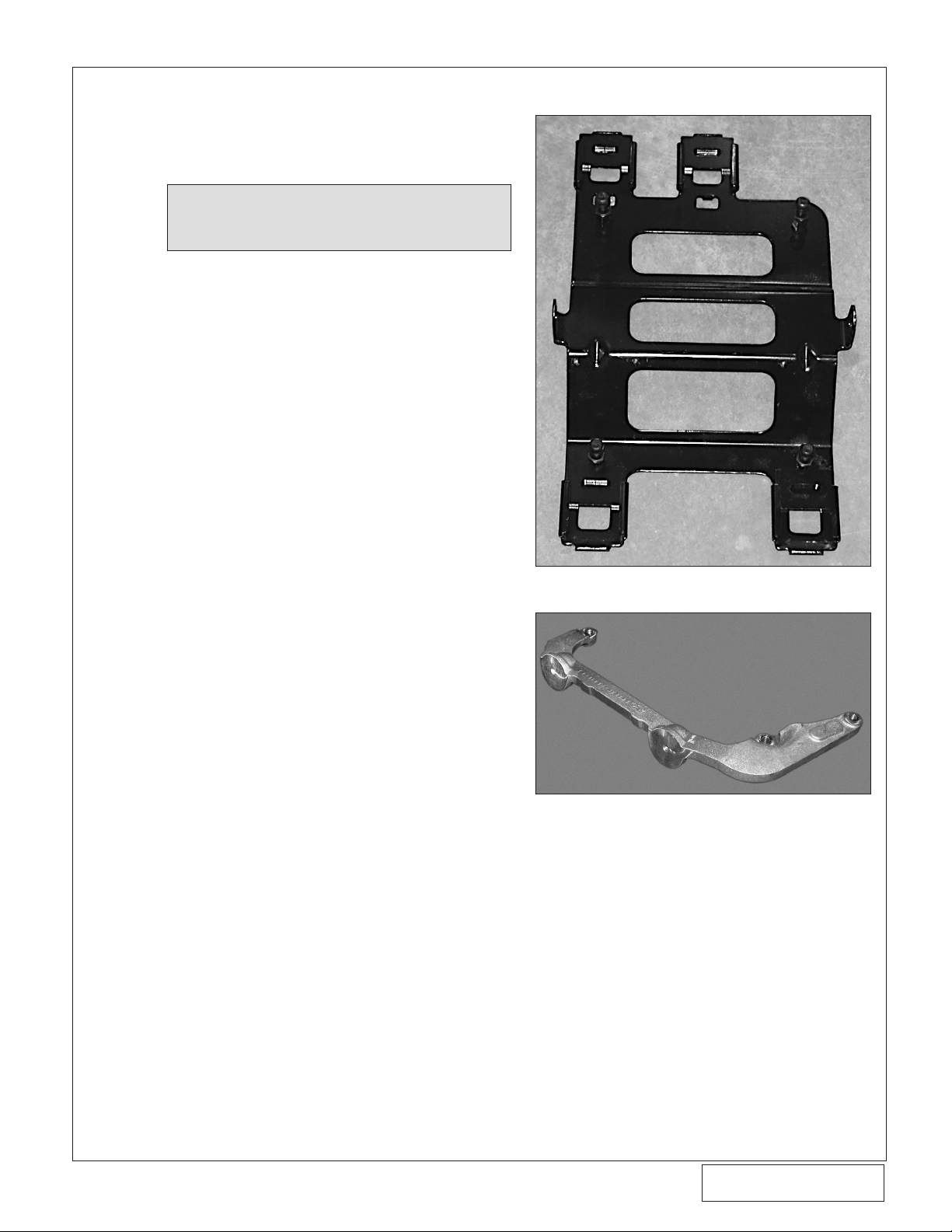
F. Mach 1 Only: Remove the shaker scoop (upper
and lower pieces), steel support bracket attached
to the top of the intake manifold and the aluminum
support bracket attached to the front cover of the
engine. (See Fig. 1-a, 1-b.)
G. Drain approximately one gallon of coolant from
the radiator. Remove the upper and lower radiator
hoses from the steel water tube junction located
around the alternator. Disconnect the water temperature sensor connector located on the water
tube.
H. Remove the steel water tube assembly from
the engine by removing the 2 nuts. Pull the tube
directly upwards.
I. Remove the coolant temperature sensor from
the factory water tube and set aside.
J. Remove the rear attachment screws that secure
the steel alternator support to the intake manifold.
Remove the two screws that attach the alternator
base to the engine block. This will allow for the
alternator to be raised. Leave the factory steel
bracket attached to the top of the alternator intact
(the two front screws will remain).
Fig. 1-a / Mach 1 Models Only
Fig. 1-b / Aluminum Bracket Removed
From Front Cover / Mach 1 Models Only
* 1999 Models and Mach 1 only
** 2001-2004 Models only
©2004 Vortech Engineering, LLC
1
All Rights Reserved, Intl. Copr. Secured
23AUG04 86-93 4V Mus. Cobra(4FR v3.1)
P/N: 4FR020-010
Page 14
P/N: 4FR020-010
©2004 Vortech Engineering, LLC
All Rights Reserved, Intl. Copr. Secured
23AUG04 86-93 4V Mus. Cobra(4FR v3.1)
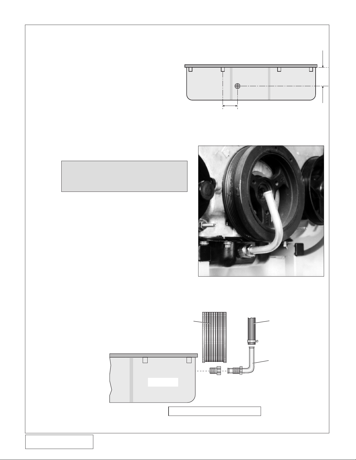
1-7/8"
5/8"
2. OIL DRAIN
OIL PAN
DRAIN HOSE
FROM
SUPERCHARGER
OIL DRAIN
TUBE
CRANK PULLEY
VIEW FROM PASSENGER SIDE
A. To provide an oil drain for the supercharger,
it is necessary to make a hole in the oil pan.
Locate and mark the hole per Fig. 2-a. The
drain hole must be punched rather than
drilled.
B. Remove the paint around the hole area.
C. Use a small center punch to perforate the
pan and expand hole. Switch to a larger
diameter punch and expand the hole further to approximately 9/16" diameter. Most
punches are made from hexagon material
and may be placed in a socket with an extension to make this procedure easier.
D. Tap the hole with a 3/8" NPT tap approximately
1/4" deep. Pack the utes of the tap with heavy
grease to hold chips. Use a small magnet to check
for any stray chips.
NOTE: This method of rolling over the lip of
the hole and tapping it works very well
if carefully done and should cause no
problems.
E. Thoroughly clean the threaded area. Apply a small
amount of silicone sealer to the new threads. Apply more sealer to the male portion of the 3/8"
NPT x 1/2" inverted are tting and secure in
hole. Make sure a seal is formed all around the
tting.
F. Thread the tube nut and 1/2" x 90° aluminum
tube into the inverted are tting by hand. Do not
tighten until after the supercharger drain hose
has been connected. (See Figs. 2 b, 2 c.)
G. Drain the engine oil and change the lter.
H. Temporarily cap off the oil drain tting to keep
out debris until drain hose is attached at a later
time.
I. Rell engine with 5W/30 synthetic or conventional
SH/CF rated motor oil.
Fig. 2-a - Front of Oil Pan
Fig. 2-b
P/N: 4FR020-010
©2004 Vortech Engineering, LLC
All Rights Reserved, Intl. Copr. Secured
23AUG04 86-93 4V Mus. Cobra(4FR v3.1)
2
Fig. 2-c
Page 15

3. OIL FEED
A. Remove the 1/4" NPT socket head plug located
perpendicular to and directly beneath the factory
oil pressure sending unit. This is found on the
engine's driver's side below the oil lter.
B. Thread the supplied 1/4" NPT #4 are x 90° tting
into the pressure sending unit mount using engine
oil on the pipe threads (see Fig. 3-a). The use of
Teon tape or other sealants is not recommended
as a small piece of either may break loose and
cause blockage of the oil feed orice, resulting
in supercharger failure. Rotate the tting so that
the are points toward the front of the vehicle.
C. Temporarily cap off the are tting to prevent dirt
from entering. The oil feed will be connected at
a later time.
4. FUEL PUMP INSTALLATION
NOTE: It is recommended when performing this
step that the fuel level in the tank be below
1/4 tank.
1/4" NPT x 90° FITTING
Fig. 3-a
A. Raise the rear of the car and support it with jack-
stands.
B. Open the fuel door and remove the fuel-cap
and the three ller neck screws using a 10mm
socket.
C. Remove the fuel lter inlet line with a 3/8 sprin-
glock tool.
D. With the weight of the fuel tank supported with a
jack, remove the bolts securing the two fuel tank
straps.
E. Slowly lower the fuel tank, allowing it to lean over
with the ller side up, until the electrical connections leading to the center mounted fuel pump
are revealed. Disconnect these two electrical
connections.
F. Remove the six bolts securing the fuel pump
access cover (on top of the fuel tank) with an
8mm wrench. Depress the two clips securing the
plastic fuel pump enclosure and slide it out of the
tank. The fuel sender oat is attached to the fuel
pump enclosure and must be handled with care.
Ensure that the tank has been lowered enough
to remove the fuel pump enclosure.
G. Remove the two screws securing the plastic fuel
pump outlet manifold to the enclosure cap. Pull
the manifold up and away from the fuel pump.
H. Remove the three screws securing the fuel pump
enclosure’s cover using a 3/16 nut-driver and remove the cover.
I. Remove the stock fuel pump from its enclosure.
Separate the rubber pump support from beneath
the lter and install it on the supplied pump. Secure the support with the new lter provided.
©2004 Vortech Engineering, LLC
3
All Rights Reserved, Intl. Copr. Secured
23AUG04 86-93 4V Mus. Cobra(4FR v3.1)
P/N: 4FR020-010
Page 16

P/N: 4FR020-010
©2004 Vortech Engineering, LLC
All Rights Reserved, Intl. Copr. Secured
23AUG04 86-93 4V Mus. Cobra(4FR v3.1)
4. FUEL PUMP INSTALLATION, cont'd.
J. Using the supplied fuel pump, reassemble the
fuel pump assembly and canister with cap.
K. Reinstall the canister assembly into the fuel tank
and reattach the electrical connections.
L. Reinstall the fuel tank, reconnect the fuel l-
ter inlet line, reattach the fuel ller neck and
reinstall the fuel cap.
M. Turn the ignition key on and check the fuel
pump for leaks.
5. FUEL INJECTOR REPLACEMENT
A. Disconnect the EGR tube from the EGR valve at
the back of the intake manifold. Remove all bolts
securing the upper manifold to the lower manifold.
Unplug the electrical connector from the throttle
body. The upper manifold should now move up
enough to access all fuel injectors.
B. Disconnect the eight (8) fuel injector wiring clips
and retainers from the fuel injectors. Release any
residual fuel pressure from the rail by opening the
schrader valve on the rail. Have a re extinguisher
nearby and use extreme caution.
C. Remove the bolts holding down the factory fuel
rail onto the intake manifold. Lift up on to the rails
evenly, removing all eight (8) injectors.
D. Using a small amount of clean motor oil, lightly
lubricate the O-rings on both ends of the Vortech
supplied fuel injectors.
E. Install the new injectors into the fuel rails with the
terminals facing outward.
F. Carefully lower the fuel rail/injector assembly
down onto the intake manifold. Check to see
that each injector has been seated properly into
the manifold.
G. Tighten down the fuel rail assembly with the
original bolts.
H. Use supplied jumper harnesses to connect the
factory fuel injector plug to the newly installed
fuel injectors (see Fig. 5-a).
I. Reinstall all components removed in step A.
P/N: 4FR020-010
©2004 Vortech Engineering, LLC
All Rights Reserved, Intl. Copr. Secured
23AUG04 86-93 4V Mus. Cobra(4FR v3.1)
Fig. 5-a
Vortech supplied
fuel injector
4
Vortech supplied jumper har-
ness (5W001-051)
Factory fuel
injector plug
Page 17

6. AIR CONDITIONING LINE MODIFICATION
NOTE: Air conditioning lines are under high pres-
sure and the uid is highly toxic. Therefore,
use extreme caution when bending the
line to avoid kinking or breaking the line.
Support the assembly as much as possible
while bending for clearance.
A. Carefully bend the high pressure air conditioning
line (the line with the pressure port and cap) so
that the pressure port rotates down (for supercharger inlet clearance). (See Fig. 6-a.)
Fig. 6-a
7. FAN RESISTOR RELOCATION (2001 and 2003-2004 Mach 1 models only)
A. 2003-2004 Mach 1: In order to remove the fan
resistor, you must unbolt the fan shroud from the
radiator. Pull the fans forward and remove the
resistor for the rear of the fans.
B. Cobra: Unsnap the resistor from the fanshroud
bracket. (See Fig. 7-b.) Pull the wire clips securing
the wires to the fan away from the shroud so that
the resistor can reach down. With the supplied
relocation bracket and sheet metal screws mount
the resistor (see Fig. 7-a).
C. SHROUD MODS: Trim the plastic which holds
the fan high/low resistor as shown in Fig. 7-b to
give clearance for the inlet duct.
Fig. 7-a
FACTORY FAN
RESISTOR LOCATION
MODIFY SHROUD
AS SHOWN
5
Fig. 7-b
©2004 Vortech Engineering, LLC
All Rights Reserved, Intl. Copr. Secured
23AUG04 86-93 4V Mus. Cobra(4FR v3.1)
P/N: 4FR020-010
Page 18

P/N: 4FR020-010
©2004 Vortech Engineering, LLC
All Rights Reserved, Intl. Copr. Secured
23AUG04 86-93 4V Mus. Cobra(4FR v3.1)
8. MAIN BRACKET ASSEMBLY/DRIVE BELT
A. Attach the supplied 1/8" NPT x 45° are tting
and oil feed hose to the oil feed tting on the supercharger. Rotate the tting so that it points forward, toward the volute side of the supercharger,
perpendicular to the front cover. When tightening
tting, use a 1/2" wrench on the oil feed base for
support.
WARNING: When threading the 1/8" NPT x 45° are
tting into the supercharger, use engine
oil on the pipe threads for lubrication.
Teon tape, paste or other sealant is not
recommended as it might loosen and
cause blockage of the oil feed orice,
resulting in supercharger failure.
B. Slide the supplied 1/2" oil drain hose onto the
supercharger drain and secure with a #8 hose
clamp.
C. Using the supplied 3/8-16 x 1.75, 2.25 bolts and
3/8" AN washers, secure the supercharger to the
Vortech aluminum mounting bracket. (See Figs.
8-a, 8-b.) Do not overtighten bolts.
Fig. 8-a
Fig. 8-b
P/N: 4FR020-010
©2004 Vortech Engineering, LLC
All Rights Reserved, Intl. Copr. Secured
23AUG04 86-93 4V Mus. Cobra(4FR v3.1)
6
Page 19

8.1 MAIN BRACKET ASSEMBLY/DRIVE BELT - 1999 Models
A. Remove the three timing cover bolts, xed idler
pulley bolt (replace the factory idler pulley bolt
with the supplied 8mm x 16 bolt and heavy duty
washer) and passenger's side alternator mounting
bolt from the front of the engine. Remove the upper bolt/stud located on the factory belt tensioner
and replace with the supplied 8mm x 25mm bolt
and washer. Remove the middle bolt also located
on the belt tensioner. (See Fig. 8.1-a.)
B. Remove the air conditioning line silencer bracket
and mounting hardware from the silencer and
engine front cover. Trim the corner of the bracket
per Fig. 8.1-b on the following page. Enlarge the
smaller of the two holes on the bracket with an
11/32" drill, remove any sharp edges around enlarged hole and reinstall onto the silencer. (See
Fig. 8.1-c.)
NOTE: When mounting the supercharger bracket
assembly to the front cover, make sure that
the air conditioning line silencer bracket
is sandwiched in between the Vortech
aluminum bracket and the front cover in
positions #1 and #2. See Fig. 8.1-c.
C. Install the supplied M8 x 1.25 threaded stud into
the passenger side alternator mount. (Make sure
the end with the least number of threads goes
into the block.)
NOTE: On 1999 models, a tensioner stop has
been added to the tensioner. This must be
removed before bracket installation.
REMOVE FACTORY BOLT/STUD AND
REPLACE WITH SUPPLIED 8mm x 65mm
ALLEN HEAD BOLT AND WASHER
REMOVE FACTORY BOLT/STUD AND
REPLACE WITH SUPPLIED 8mm X 25
BOLT AND WASHER
REMOVE FACTORY HARDWARE
(NEW SUPERCHARGER
BRACKET MOUNTING HOLES)
FACTORY A/C SUCTION LINE
SILENCER BRACKET
MOUNTING HOLES
REMOVE FACTORY BOLT AND WASHER
AND REINSTALL FACTORY IDLER WITH
SUPPLIED 8mm x 16 BOLT AND HEAVYDUTY WASHER
1999 models
Fig. 8.1-a
7
INSTALL 8mm
BOLT HERE IF 1/2"
SQUARE DRIVE
IN TENSIONER IS
NOT PROVIDED.
©2004 Vortech Engineering, LLC
All Rights Reserved, Intl. Copr. Secured
23AUG04 86-93 4V Mus. Cobra(4FR v3.1)
P/N: 4FR020-010
Page 20

P/N: 4FR020-010
©2004 Vortech Engineering, LLC
All Rights Reserved, Intl. Copr. Secured
23AUG04 86-93 4V Mus. Cobra(4FR v3.1)
A/C LINE
SILENCER
BRACKET
VIEW FROM FRONT
VORTECH
IDLER PULLEY
VORTECH
MOUNTING
BRACKET
ALTERNATO
R
OIL DRAIN HOSE
#1
#2
VORTECH
#3
8mm X 140 BOLT AND WASHER
8mm X 140 BOLT
AND WASHER
8mm X 70 BOL
T
AND WASHER
8mm X 70 BOLT
AND WASHER
8mm
THREADED STUD
,
WASHER AND NUT
SANDWICH TABS BETWEEN
ENGINE FRONT COVER AND
SUPERCHARGER BRACKET
ENLARGE
TO
11/32"
VIEW A
1/2”
1/2”
REMOVE THE SHADED
AREA
FOR SUPER-
CHARGER MOUNTING
BRACKET CLEARANCE
8.1 MAIN BRACKET ASSEMBLY/DRIVE BELT - 1999 Models, cont'd.
Fig. 8.1-c
P/N: 4FR020-010
©2004 Vortech Engineering, LLC
All Rights Reserved, Intl. Copr. Secured
23AUG04 86-93 4V Mus. Cobra(4FR v3.1)
Fig. 8.1-b
8
Page 21

8.1 MAIN BRACKET ASSEMBLY/DRIVE BELT - 1999 Models, cont'd.
VIEW FROM DRIVER'S SIDE
VORTECH
IDLER PULLEY
VO
RTECH
SUPERCHARGER
MOUNTING BRACKET
STEEL IDLER
SPACER
ALTERNATOR
BOSS
HOLE POSITION #3
(SEE GRAPHIC ON
NEXT PAGE)
SUPPLIED 8mm STUD
(THREAD COMPLETELY
INTO BLOCK UNTIL
THREADS STOP)
ENGINE
BLOCK
E. Loosen and remove the three nuts securing the
factory coolant reservoir to the car. Temporarily
move aside to provide room to mount the supercharger. (Do not remove any hoses or connectors
from reservoir.)
F. Remove the factory anged water pump pulley
and replace with the supplied non-anged pulley.
G. Following Figs. 8.1-c & 8.1-d, attach the
supercharger/aluminum bracket assembly with
the Vortech idler pulley and idler spacer to the
alternator stud and front cover using the supplied 8mm hardware. Route the new, longer belt
around the outside of the supercharger drive pulley, then around the inside of the Vortech idler.
Finish routing the belt around all of the pulleys,
except for the water pump. Make sure that the
Vortech idler pulley and spacer (located against
the alternator base), are seated and located in
their proper positions before tightening down the
bolts (see Fig. 8.1-e for belt routing).
NOTE: When installing the Vortech idler pulley,
make sure that the bearing shim located
between the bearings in the pulley allows
for complete insertion of the idler spacer
and bracket pilot. Install the steel idler
spacer into the idler pulley and verify that
the shim is not interfering with the idler
spacer pilot.
Fig. 8.1-d
9
1999 Models Only
All Rights Reserved, Intl. Copr. Secured
23AUG04 86-93 4V Mus. Cobra(4FR v3.1)
©2004 Vortech Engineering, LLC
P/N: 4FR020-010
Page 22

P/N: 4FR020-010
©2004 Vortech Engineering, LLC
All Rights Reserved, Intl. Copr. Secured
23AUG04 86-93 4V Mus. Cobra(4FR v3.1)
8.1 MAIN BRACKET ASSEMBLY/DRIVE BELT - 1999 Models, cont'd.
S/C
FACTORY
IDLER
VORTECH
IDLER
WA
TER
PUMP
CRANK
A/C
TENSIONER
POWER
STEERING
ALT.
PUSH BELT OVER THE TOP OF THE WATER
PUMP PULLEY LAST
* PUSH BELT IN BETWEEN THE
IDLER AND TENSIONER TO
OBTAIN WRAP AROUND
ACCESSORY AND
SUPERCHARGER PULLEYS
*
H. After the bracket has been fully secured (the belt
should be properly routed around/under all pulleys
except for the water pump), use a 1/2" breaker
bar or ratchet to release the belt tension. Push
the belt over the top radius of the water pump
pulley, underneath the crank pulley, over the top
of the tensioner pulley and release the tensioner
(see Fig. 8.1-e).
I. Route the oil drain hose down to the oil pan tube
previously installed. The hose must be routed
downhill, free from dips and kinks. Trim hose end
if necessary, slide onto the drain tube and secure
with #8 hose clamp. Support tting in oil pan with
a wrench while tightening the drain tube tting.
IMPORTANT: It is imperative that the tensioner does
not get overloaded when being pulled
down during belt installation. Bending of the tensioner may cause belt
throwing/shredding problems when
vehicle is driven at high speeds.
J. Route the oil feed hose next to the drain hose,
down to the feed tting and secure. Use tie wraps
to fasten the lines together.
K. Reinstall the factory coolant reservoir and se-
cure.
Fig. 8-h
1999 only
BELT ROUTING
P/N: 4FR020-010
©2004 Vortech Engineering, LLC
All Rights Reserved, Intl. Copr. Secured
23AUG04 86-93 4V Mus. Cobra(4FR v3.1)
Fig. 8.1-e
10
Page 23

REMOVE FACTORY BOLT/STUD AND
REPLACE WITH SUPPLIED 8mm x 65mm
ALLEN HEAD BOLT & WASHER
REMOVE FACTORY
BOLT, WASHER &
IDLER & INSTALL
THE VORTECH
SUPPLIED
COMPOSITE IDLER
USING FACTORY
HARDWARE
REMOVE FACTORY
HARDWARE (NEW
SUPERCHARGER
BRACKET
MOUNTING BOLTS)
INSTALL M8 x 1.25 STUD (SHORT
THREADED END GOES INTO THE
BLOCK)
8.2 MAIN BRACKET ASSEMBLY/DRIVE BELT - 2001-2004 Models, cont'd.
A. Remove the three timing cover bolts,
xed idler pulley bolt (replace the factory idler with the supplied Vortech
composite idler) and passenger's side
alternator mounting bolt from the front
of the engine. (See Fig. 8.2-a.)
B. Remove the air conditioning line silencer
and mounting hardware from the engine
front cover.
C. Install the supplied M8 x 1.25 threaded
stud into the passenger's side alternator mount. (Make sure the end with the
least number of threads goes into the
block.)
D. Loosen and remove the three nuts se-
curing the factory coolant reservoir to the
car. Temporarily move aside to provide
room to mount the supercharger. (Do not
remove any hoses or connectors from
the reservoir.)
E. Mach 1 Models Only: Remove the fac-
tory water pump pulley and replace with
the supplied aluminum pulley. Use the
factory bolts.
F. Mach 1 Models Only: Remove the belt
tensioner from the front cover. Grind the
top belt shield section off as seen in Fig.
8.2-b.
G. Following Figs. 8.2-c through 8.2-m
(Mach 1 Models Ignore Fig. 8.2-l),
rst route the Vortech supplied supercharger belt and then attach the idler
relocation assembly and mounting
bracket/supercharger assembly to the
front cover using the supplied 8mm
hardware. Finish by routing
around all of the pulleys along
with the supercharger pulley,
except for the water pump.
H. After the bracket has been
fully secured (the belt should
be properly routed around/
under all pulleys except the
water pump). Use a large pair
of channel locks to release
the belt tension. Push the
belt over the top radius of
the water pump pulley, then
release the tension. (See Fig.
8.2-n.)
I. Secure the air conditioner
canister to the Vortech
mounting bracket as shown
in Fig. 8.2-m.
IMPORTANT: It is imperative that the ten-
sioner does not get overloaded
when being pulled down during belt installation. Bending of
the tensioner may cause belt
throwing/shredding problems
when vehicle is driven at high
speeds.
J. Route the oil feed hose next to the
drain hose down to the feed tting and
secure. Use tie wraps to fasten the lines
together.
K. Reinstall the factory coolant reservoir
and secure.
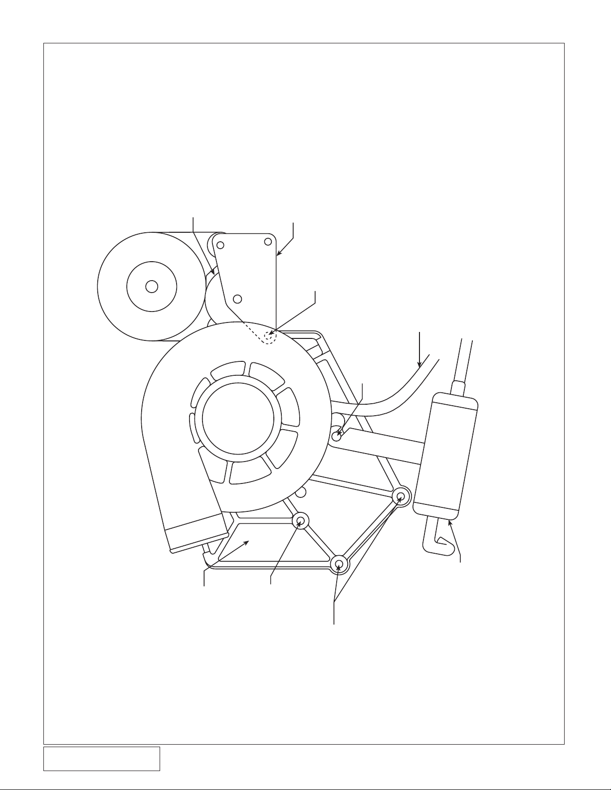
GROUND SECTION TO
CLEAR MOUNTING BRACKET
Fig. 8.2-b / Mach 1 Only
Fig. 8.2-a
11
©2004 Vortech Engineering, LLC
All Rights Reserved, Intl. Copr. Secured
23AUG04 86-93 4V Mus. Cobra(4FR v3.1)
P/N: 4FR020-010
Page 24

P/N: 4FR020-010
©2004 Vortech Engineering, LLC
All Rights Reserved, Intl. Copr. Secured
23AUG04 86-93 4V Mus. Cobra(4FR v3.1)
8.2 MAIN BRACKET ASSEMBLY/DRIVE BELT - 2001-2004 Models
SECTION VIEW OF VORTECH
MOUNTING BRACKET
SPACER
ALTERNATOR
BRACKET 1
8mm STUD
(THREAD THE END
WITH THE LEAST
NUMBER OF THREADS
INTO THE BLOCK UNTIL
THE THREADS STOP)
5/16-18 x 1.75 SCREWS w/WASHERS
ALTERNATOR
BRACKET 2
RELOCATED FACTORY
IDLER (open side must face
toward the alternator)
IDLER ASSEMBLY
8mm NUT
WASHER
2001 ONLY
3/8-16 x 1.00 SCREW
2A017-016 BEARING PILOT
5/16-18 x 1.00
SCREW
w/WASHER
8mm x 1.25 x 130mm
SCREW w/WASHER
2001-2004 ONLY
Fig. 8.2-c
P/N: 4FR020-010
©2004 Vortech Engineering, LLC
All Rights Reserved, Intl. Copr. Secured
23AUG04 86-93 4V Mus. Cobra(4FR v3.1)
12
Page 25

8.2 MAIN BRACKET ASSEMBLY/DRIVE BELT - 2001-2004 Models, cont'd.
INSTALL SUPPLIED COMPOSITE
IDLER USING FACTORY HARDWARE
ROUTE BELT BEFORE
INSTALLING BRACKETRY
Fig 8.2-d / Step 1
ALTERNATOR BRACKET AND SPACER
(THREADED TIGHTLY INTO BLOCK
SUPPLIED STUD
W/SHORT THREADED END)
Fig 8.2-e / Step 2
13
Fig 8.2-f / Step 3 - Install supercharger/bracket
assembly as shown
©2004 Vortech Engineering, LLC
All Rights Reserved, Intl. Copr. Secured
23AUG04 86-93 4V Mus. Cobra(4FR v3.1)
P/N: 4FR020-010
Page 26

P/N: 4FR020-010
©2004 Vortech Engineering, LLC
All Rights Reserved, Intl. Copr. Secured
23AUG04 86-93 4V Mus. Cobra(4FR v3.1)
8.2 MAIN BRACKET ASSEMBLY/DRIVE BELT - 2001-2004 Models, cont'd.
Fig. 8.2-g / Step 4 - Install alternator bracket 2
with idler plate assembly
5/16-18 x 1.75 BOLTS/WASHERS
LOOSELY INSTALLED
INSTALL w/"OPEN" SIDE
TOWARD ENGINE
BEARING PILOT WASHER
(STEP FITS INTO BEARING BORE)
Fig. 8.2-h / Step 5
P/N: 4FR020-010
©2004 Vortech Engineering, LLC
All Rights Reserved, Intl. Copr. Secured
23AUG04 86-93 4V Mus. Cobra(4FR v3.1)
14
Fig. 8.2-i / Step 6
Page 27

8.2 MAIN BRACKET ASSEMBLY/DRIVE BELT - 2001-2004 Models, cont'd.
M8 NUT w/ WASHER
ROUTE BELT AS SHOWN
Fig. 8.2-j / Step 7
PLACE ALTERNATOR DOWN ONTO
THE 5/16-18 SCREWS AND SECURE
(MAKE SURE THE WASHERS ARE
PROPERLY LOCATED UNDER SCREW
HEADS)
SECURE BRACKETRY USING SUPPLIED
M6 x 1.00 x 75 SCREWS W/WASHERS
SUPPLIED SPACER (ONE EACH SIDE)
Fig. 8.2-k / Step 8 - Complete tightening hardware
15
Fig. 8.2-l / Step 9 (Cobra Models Only)
©2004 Vortech Engineering, LLC
All Rights Reserved, Intl. Copr. Secured
23AUG04 86-93 4V Mus. Cobra(4FR v3.1)
P/N: 4FR020-010
Page 28
P/N: 4FR020-010
©2004 Vortech Engineering, LLC
All Rights Reserved, Intl. Copr. Secured
23AUG04 86-93 4V Mus. Cobra(4FR v3.1)
8.2 MAIN BRACKET ASSEMBLY/DRIVE BELT - 2001-2004 Models, cont'd.
ALTERNATOR
VORTECH
MOUNTING
BRACKET
8MM X 70 BOLT
AND
WASHER
A/C CANISTER
BRACKET
OIL DRAIN
HOSE
8MM x 140 BOLT
AND WASHER
RELOCATED
STOCK IDLER
IDLER RELOCATION
ASSEMBL
Y
8MM THREADED STUD,
WASHER AND NUT
MOUNTING LOCATION
FOR A/C CANISTER
2001-2004 Only
Fig. 8.2-m
P/N: 4FR020-010
©2004 Vortech Engineering, LLC
All Rights Reserved, Intl. Copr. Secured
23AUG04 86-93 4V Mus. Cobra(4FR v3.1)
16
Page 29
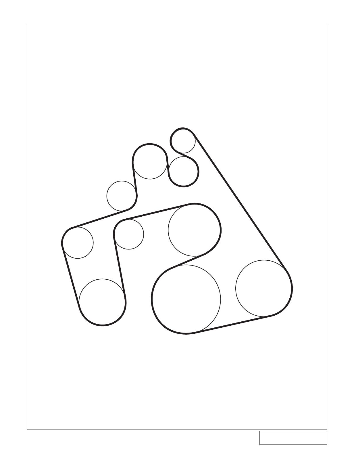
RELOCATED
FACTORY
IDLER
RELOCATED
ALTERNATOR
PULLEY
SUPERCHARGER
PULLEY
TENSIONER
VORTECH
SUPPLIED
IDLER
A/C
FACTORY
IDLER
WATER
PUMP
CRANK
POWER
STEERING
8.2 MAIN BRACKET ASSEMBLY/DRIVE BELT - 2001-2004 Models, cont'd.
BELT ROUTING
2001-2004 Only
Fig. 8.2-n
17
©2004 Vortech Engineering, LLC
All Rights Reserved, Intl. Copr. Secured
23AUG04 86-93 4V Mus. Cobra(4FR v3.1)
P/N: 4FR020-010
Page 30

P/N: 4FR020-010
©2004 Vortech Engineering, LLC
All Rights Reserved, Intl. Copr. Secured
23AUG04 86-93 4V Mus. Cobra(4FR v3.1)
9. RADIATOR HOSE/WATER TUBE
A. Remove the upper radiator hose from the
radiator and modify (cut) as shown in Fig.
9-b on page 19.
B. With the lower radiator hose still connected
to the radiator, remove 2" from the end previously connected to the factory water tube.
Set the 2" section aside.
C. Following Fig. 9-c on page 19, pre-assemble
the Vortech supplied "L" and "U" bent water
tubes using the 2" hose (section removed
in the previous step) and the supplied #20
clamps. Do not tighten clamps until assembly
is mounted on the engine.
D. Thread the factory coolant temperature
sensor into the Vortech water tube using
pipe thread sealant on the sensor threads.
Make sure that the sensor is installed into
the underside of the "U" bend (see Fig.
9-a).
E. 99-01 Cobra: Install the two supplied
O-rings into the O-ring grooves located on
each end of the Vortech water tube assembly.
Apply a small amount of anti-freeze around
each O-ring to act as a lubricant for easier
installation. With the "U" and "L" bends put
together as one assembly, install the unit into
the engine block in the factory water tube
location making sure that both pipe tabs
are aligned onto the intake manifold holes.
Push both pipes down until the tabs and/or
pipes hit bottom. Secure the assembly with
the two factory nuts, or supplied 6mm nuts
and washers if the factory water tube was
originally attached to the alternator.
(2003-2004) Mach 1 Models: Install the
two supplied O-rings into the O-ring grooves
located on each end of the Vortech water
tube assembly. Apply a small amount of
anti-freeze around each O-ring to act as
a lubricant for easier installation. Place the
two supplied aluminum spacers (.28" thick)
between the bottom of each of the water
pipe mounting tabs and the intake manifold ange where the factory water pipes
were originally attached. With the "U" and
"L" bends put together as one assembly,
install the unit into the engine block in the
factory water tube location making sure that
both pipe tabs are aligned onto the intake
manifold holes. Push both pipes down until
the tabs and/or pipes hit bottom. Make sure
that the tabs are on the top of the supplied
.28" spacers. Secure the assembly with the
two factory screws.
COOLANT TEMPERATURE SENSOR
Fig. 9-a
F. Reattach the factory coolant sensor con-
nector.
G. Reinstall the modied upper radiator hose
to the radiator with the factory clamp.
H. As shown in Fig. 9-d on the next page, re-
move 2-1/2" from the long leg of the Vortech
supplied 1-1/2" diameter x 90° hose. Attach
the hose, along with the factory radiator
hose, to the supplied 1-1/2" splice using
#24 clamps. Connect the entire assembly
to the new Vortech water tube.
I. Attach the open end of the lower radiator
hose to the remaining barb on the Vortech
water tube and secure with a #20 hose
clamp.
J. Rell radiator. Completely ll engine block
through the 3/8" NPT water ll port on the
Vortech water tube. Plug ll port with supplied 3/8" NPT plug.
P/N: 4FR020-010
©2004 Vortech Engineering, LLC
All Rights Reserved, Intl. Copr. Secured
23AUG04 86-93 4V Mus. Cobra(4FR v3.1)
18
Page 31

CUT
DISCARD
4-3/4"
RADIATOR
ENGINE
RADIATOR
VORTECH
WA
TER TUBE
1-1/2" DIAMETER
SUPPLIED HOSE
2-1/2"
CUT
SUPPLIED (3X)
#24 CLAMPS
FACTORY
CLAMP
SUPPLIED
1-1/2" DIA. SPLICE
CUT FROM LONG
END AND
DISCARD
9. RADIATOR HOSE/COOLANT TUBE, cont'd.
"U" BEND
ASSEMBLY
COOLANT TEMPERATURE
SENSOR (UNDERSIDE OF
TUBE)
"L" BEND
ASSEMBLY
LOWER RADIATOR
HOSE CONNECTION
UPPER RADIATOR
HOSE CONNECTION
SUPPLIED #20
CLAMPS (3X)
WA
TER FILL/AIR
PURGE
(3/8" NPT PLUG)
TOP VIEW
2" WIDE HOSE
REMOVED FROM
THE TOP END OF
THE LOWER FACTOR
Y
RADIATOR HOSE
Fig. 9-b
Mach 1 Models Only: Place .28" spacers under tabs
UPPER
RADIATOR HOSE (STOCK)
VORTECH
WATER TUBE ASSEMBLY
19
Fig. 9-c
Fig. 9-d
©2004 Vortech Engineering, LLC
All Rights Reserved, Intl. Copr. Secured
23AUG04 86-93 4V Mus. Cobra(4FR v3.1)
P/N: 4FR020-010
Page 32

P/N: 4FR020-010
©2004 Vortech Engineering, LLC
All Rights Reserved, Intl. Copr. Secured
23AUG04 86-93 4V Mus. Cobra(4FR v3.1)
10. AIR INLET
FRONT
INSIDE
FRONT
PASSENGER
FENDERWELL
#64 CLAMPS
SLEEVE
ALUMINUM
REDUCER ELBOW
FACTORY
STUDS & NUTS
INT
AKE AIR
TEMPERATURE
SENSOR
MAF
BRA
CKET
MAF
METER
A. Using the supplied 1/4-20 hardware, mount the
supplied MAF meter to the Vortech MAF bracket
and secure (see Fig. 10-a for orientation). Remove
the factory MAF screen before attaching the meter
to the new MAF bracket.
B. Attach the supplied K & N air lter, 4" sleeve, 90°
x 3-1/2" x 4" elbow and #64 hose clamps to the
MAF and secure.
C. Mach 1 Models Only: Cut the outer two wires
attached to the MAF harness plug approximately
2" from the MAF connector. (See Fig. 10-h.)
Connect the gray with red stripe wire coming from
the main harness to the red wire in the supplied
IAT sensor harness using solder and the supplied
shrink sleeve.Connect the gray wire coming from
the main harness to the black/brown wire on the
supplied IAT sensor harness using solder and the
supplied shrink sleeve.
D. Insert the factory air temperature sensor into the
rubber grommet located on the side of the 90°
elbow. Lubricate it for easier t.
E. Working from beneath the vehicle, remove the
two factory nuts and washers from the passenger
side lower fender valence. Mount the MAF/bracket
assembly onto the existing studs using the same
washers and nuts originally removed. (See Fig.
10-a).
F. Using a #52 hose clamp, connect the piece of
3-1/2" ex hose to the elbow attached to the MAF
meter and route it through the opening in the right
side inner fender toward the supercharger. Make
sure that the 3-1/2" ex hose does not contact
or rub on the edge of the inner fender opening
(eventual hose failure will result if the hose is not
properly routed).
G. Route the factory temperature sensor and MAF
sensor connectors out through the inner fender
opening. Reattach the connectors to the relocated
sensors.
H. Connect the supplied molded inlet duct onto the
supercharger inlet (see Fig. 10-b) using the 3-1/2"
sleeve and #56 hose clamps provided.
I. Attach the supplied 1" x 90° rubber hose and #16
hose clamp to the 3/4" x 1" straight hose tting
located on the inlet duct. (See Fig. 10-c.)
J. Connect the previously installed 3-1/2" ex hose
to the inlet duct and secure with the #52 clamp.
K. Install the supplied length of 3/4" hose from the
inlet duct to the crankcase breather tting (see
Fig. 10-d). Trim hose length as necessary.
L. Take the supplied 5/8" rubber end cap and install
it on the 5/8" boss on the molded inlet duct.
VIEW FROM INSIDE ENGINE COMPARTMENT
(Steel inner fender not shown for ease of description)
Fig. 10-a
Fig. 10-b
P/N: 4FR020-010
©2004 Vortech Engineering, LLC
All Rights Reserved, Intl. Copr. Secured
23AUG04 86-93 4V Mus. Cobra(4FR v3.1)
20
Page 33

10. AIR INLET, cont'd.
3” x Ø1” HOSE
(TRIM TO FIT)
TO DISCHARGE
TUBE
1” UNION
1999-2004 4V FORD MUSTANG AFTERCOOLED AND
NON-AFTERCOOLED AIR INLET/BYPASS ASSEMBLY
8” x Ø1” HOSE
(TRIM TO FIT)
Ø1” x 90° ELBOW TO 1” FITTING
ON INLET DUCT
INLET DUCT
STRAIGHT FITTING
VIEW FROM FRONT
OF VEHICLE
TO MANIFOLD PRESSURE/VACUUM
#16 HOSE CLAMPS
BYPASS
VALV
E
Fig. 10-c
21
©2004 Vortech Engineering, LLC
All Rights Reserved, Intl. Copr. Secured
23AUG04 86-93 4V Mus. Cobra(4FR v3.1)
P/N: 4FR020-010
Page 34

P/N: 4FR020-010
©2004 Vortech Engineering, LLC
All Rights Reserved, Intl. Copr. Secured
23AUG04 86-93 4V Mus. Cobra(4FR v3.1)
10. AIR INLET, cont'd.
VORTECH SUPPLIED 3/4" PLASTIC ELBOW
INSERTED INTO VALVE COVER
HOSE CONNECTS TO INLET DUCT
3/4" HOSE TRIM TO FIT
FRONT OF VEHICLE
Fig. 10-d
RIGHT SIDE VALVE COVER BREATHER
P/N: 4FR020-010
©2004 Vortech Engineering, LLC
All Rights Reserved, Intl. Copr. Secured
23AUG04 86-93 4V Mus. Cobra(4FR v3.1)
22
Page 35

10. AIR INLET, cont'd.
M. (Mach 1 Models Only):
1. Remove the factory plastic PCV tube from the
driver side of the engine and discard. Insert
the large end of the supplied PCV valve into
the factory rubber PCV elbow attached to the
rear of the driver's side valve cover. Attach the
supplied 5/8" bent tube to the intake manifold
port previously connected to the plastic PCV
tube using the supplied short length of 5/8"
hose, 3/8" hose piece and the brass 3/8" to
5/8" reducer as shown. (See Figs. 10-e,
10-f.) Secure the hoses with the supplied #6
hose clamps.
2. Mark and modify the aluminum air scoop base
as shown. (See Fig. 10-g ). If you have access
to a machine shop with a milling machine, this
is the ideal method. If not, drill the marked
location with a hole saw at each corner and
then cut the remaining portion out with an
abrasive cut-off wheel, grinder or jigsaw. This
is an alternative way to provide a clean hole.
3/8" HOSE
5/8' HOSE
SUPPLIED
PCV VALVE
FACTORY
RUBBER
ELBOW
5/8' - 3/8'
UNION
Fig. 10-e / (Mach 1 Models Only)
SUPPLIED PCV TUBE
Fig. 10-f / (Mach 1 Models Only)
2-1/2"
2-1/8"
Fig. 10-g / Modify Air Scoop Base as Shown
(Mach 1 Models Only)
2-1/4"
3-3/4"
23
©2004 Vortech Engineering, LLC
All Rights Reserved, Intl. Copr. Secured
23AUG04 86-93 4V Mus. Cobra(4FR v3.1)
P/N: 4FR020-010
Page 36

P/N: 4FR020-010
©2004 Vortech Engineering, LLC
All Rights Reserved, Intl. Copr. Secured
23AUG04 86-93 4V Mus. Cobra(4FR v3.1)
GRAY WIRE
CONNECT TO THE BLACK/BROWN
AIR TEMP SENSOR WIRE
GRAY w/RED STRIPE WIRE
CONNECT TO RED
AIR TEMP SENSOR WIRE
RED
BLACK/BROWN
SUPPLIED IAT SENSOR CONNECTOR
MAF PLUG
LEAVE APPROX. 2" OF
WIRE ATTACHED TO PLUG
CUT TWO OUTER
WIRES HERE
10. AIR INLET, cont'd.
Fig. 10-h / MAF Modications
(Mach 1 Models Only)
P/N: 4FR020-010
©2004 Vortech Engineering, LLC
All Rights Reserved, Intl. Copr. Secured
23AUG04 86-93 4V Mus. Cobra(4FR v3.1)
24
Page 37

10. AIR INLET, cont'd
FRONT VIEW AFTER
MODIFICATION
USE THE BRACKET PROVIDED
AS A TEMPLATE AND
DRILL 2 Ø5/16" HOLES
DRIVER SIDE VIEW
AFTER MODIFICATION
THIS PORTION REMOVED
AND DISCARDED
.50
2.25
1.75
3. Modify the steel air scoop base mount as
shown. (See Figs. 10-i, 10-j.) A bandsaw is
the best tool to use. An abrasive cut-off wheel
or hacksaw may also be used.
4. Temporarily place the modied steel air scoop
base into its factory location on top of the
intake manifold. Loosely install the two factory
screws that secure the rear of the bracket to
the intake manifold (do not tighten at this time).
The two supplied relocation brackets must be
attached to the modied steel scoop base.
Fig. 10-i / Modied Shaker Bracket
(Mach 1 Models Only)
Fig. 10-j / Bracket mods (Mach 1 Only)
25
©2004 Vortech Engineering, LLC
All Rights Reserved, Intl. Copr. Secured
23AUG04 86-93 4V Mus. Cobra(4FR v3.1)
P/N: 4FR020-010
Page 38

P/N: 4FR020-010
©2004 Vortech Engineering, LLC
All Rights Reserved, Intl. Copr. Secured
23AUG04 86-93 4V Mus. Cobra(4FR v3.1)
10. AIR INLET, cont'd
Referring to Figs. 10-k, 10-l, attach the driver's
side relocation bracket to the alternator and
the underside of the modied steel air scoop
base and align. Mark and drill two 5/16" holes
in the modified scoop base. Permanently
attach the relocation bracket to the modied
steel air scoop base using the 1/4-20 x .75
screws, nuts and washers.
5. Remove the front passenger's side intake
manifold cover bolt. (See Fig. 10-m.) Locate
the driver's side relocation bracket in between
the bottom of the modied steel air scoop base
and the front passenger's side intake manifold
cover bolt. Re-install the intake manifold cover
bolt through the new bracket. Mark and drill a
5/16" hole in the modied steel air scoop base.
Permanently attach the relocation bracket to
the modied steel air scoop base using the
1/4-20 x .75" screw, nut and washer. Tighten
the two factory screws securing the steel
air scoop base at the rear of the intake
manifold.
6. Re-install the modied aluminum shaker scoop
assembly onto the modied steel air scoop
base using the factory hardware and rubber
grommets. Ensure the assembly alignment by
carefully closing the hood. Adjust the scoop
base if necessary.
SUPPLIED 1/4-20 SCREWS,
NUTS, WASHERS
SUPPLIED
BRACKET
SUPPLIED
BRACKET
Fig. 10-k / (Mach 1 Models Only)
Fig. 10-l / Modied Shaker Bracket w/Vortech
Brackets Attached (Mach 1 Models Only)
P/N: 4FR020-010
©2004 Vortech Engineering, LLC
All Rights Reserved, Intl. Copr. Secured
23AUG04 86-93 4V Mus. Cobra(4FR v3.1)
26
SUPPLIED
BRACKET
FACTORY
MANIFOLD
COVER BOLT
Fig. 10-m / (Mach 1 Models Only)
Page 39

AFTERCOOLER KITS ONLY: If an aftercooler kit is
being installed, please substitute the supplied "Maxow Power Cooler" instructions
in place of step 11. Resume at step 12 after
the completion of the Aftercooler installation.
11. SUPERCHARGER DISCHARGE
A. Slide the 4-1/2" diameter sleeve and #72 hose
clamps onto the throttle body. Slide the 2-3/4"
sleeve and #44 hose clamps onto the supercharger
discharge.
B. Install the 1" x 3" hose, #16 hose clamps and
bypass valve onto the discharge tube with the
5/32" nipple on the valve pointing down.
C. Install the aluminum discharge tube onto the
throttle body. Slide the 3-1/2" sleeve and #56
clamps onto the round end of the tube. Next,
connect the supercharger to the aluminum tube
using the long discharge tube/bypass valve
assembly. Align the bypass valve, all hoses and,
tighten all clamps. If necessary, trim the 1" bypass
hose lengths for best t. (See Fig. 11-a.)
D. Attach the supplied 5/32" vacuum line to the
bypass valve. Using the supplied 5/32" TEE,
connect the hose to the fuel pressure sensor
(located on the fuel rail) vacuum port.
E. Install supplied laser-etched plaque on top
of mounting bracket using the supplied #10
screws.
Fig. 11-a
27
©2004 Vortech Engineering, LLC
All Rights Reserved, Intl. Copr. Secured
23AUG04 86-93 4V Mus. Cobra(4FR v3.1)
P/N: 4FR020-010
Page 40

P/N: 4FR020-010
©2004 Vortech Engineering, LLC
All Rights Reserved, Intl. Copr. Secured
23AUG04 86-93 4V Mus. Cobra(4FR v3.1)
12. ECM MODULE INSTALLATION
NOTE: When the ECM is sent, the following step will be
performed by Vortech to ensure proper cleaning
and module installation. (Step 12 is for reference
only.)
A. Double check that the battery cable is disconnected
from the vehicle.
B. Remove the passenger side front kickpanel from
the interior of the vehicle. Remove the sound
deadening material (if any) that is covering
the ECM. Remove the plastic ECM hold-down
bracket.
C. Using a 10mm socket or wrench, remove the
harness and plug from the ECM (as you loosen
the bolt, the connector will slowly release).
Remove the ECM from the vehicle.
D. Gently remove the plastic service port cover on the
opposite end from the main harness connection.
The main circuit board with a double sided
electrical edge connector will now be exposed
(see Fig. 12-a).
E. Using alcohol and a cotton swab, carefully clean
the grease off of both sides of the main circuit
board service contacts.
F. Using a sharp knife, small at screwdriver or
scraper, gently scrape the remaining thin layer
of silicone off of the contacts. This can easily
be done by removing the corner screws on the
ECM and opening the cover to better expose
the connector to be cleaned. DO NOT remove
or damage the electrical contacts. If the silver
contacts start to give off ne metal shavings, you
are done. STOP. It is extremely important that
all of the silicone be removed from the contacts.
If the surface is not completely clean, the
vehicle may not start or run properly. If the ECM
cover was removed, reinstall it at this time.
Fig. 12-a / ECM & Module Alignment
Fig. 12-b / Proper Module Installation
Fig. 12-c / Improper Module Installation
NOTE: Improper contact cleaning is the largest rea-
G. With the ECM service port contacts now clean,
you are ready to install the ECM module. Align
the module with the ECM (see Figs. 12-b,
12-c). Slide the module onto the ECM by applying
gentle pressure evenly. Apply the supplied section
of adhesive tape to the top of the ECM and module
to resist movement from vibration.
H. Reinstall the ECM into the vehicle. In some cases,
the extra height of the ECM module will not allow
the use of the factory ECM bracket. Reconnect
the factory harness and reinstall the factory kick
panel.
P/N: 4FR020-010
©2004 Vortech Engineering, LLC
All Rights Reserved, Intl. Copr. Secured
23AUG04 86-93 4V Mus. Cobra(4FR v3.1)
son ECM modules fail or work improperly.
28
Page 41

WARNING: Do not attempt to operate the vehicle
until ALL components are installed and
ALL operations are completed including
the nal check.
13. FINAL CHECK
NOTE: Once the ECM is recieved back from
Vortech with the ECM module installed,
reinstall the ECM into the vehicle. In some
cases, the extra height of the ECM module will not allow the use of the factory
hold-down bracket. Reconnect the factory
harness and reinstall the factory kick panel.
A. Reconnect the battery.
B. If your vehicle has gone over 20,000 miles since
its last spark plug change, you will need to
change the spark plugs now before test driving
the vehicle.
C. Check all fittings, nuts, bolts and clamps for
tightness. Pay particular attention to oil and fuel
lines around moving parts, sharp edges and
exhaust system parts. Make sure all wires and
lines are properly secured with clamps or tie
wraps.
D. Double check water pump pulley bolts for
tightness.
E. Check all uid levels, making sure that your tank(s)
is/are lled with 91 octane or higher fuel before
commencing test drive.
F. Start the engine and allow to idle a few minutes,
then shut off.
G. Recheck to be sure that no hoses, wires, etc. are
near exhaust headers or moving parts and for
signs of any uid leakage. (See Fig. 13-a.)
H. PLEASE TAKE SPECIAL NOTE: Operating the
vehicle without ALL the subassemblies completely
and properly installed may cause FAILURE OF
MAJOR COMPONENTS.
I. Test drive the vehicle.
J. Read the STREET SUPERCHARGER SYSTEM
OWNER'S MANUA L AND RET U R N THE
COMPLETED WARRANTY REGISTRATION
FORM within thirty (30) days of purchasing your
supercharger system .
Fig. 13-a
29
©2004 Vortech Engineering, LLC
All Rights Reserved, Intl. Copr. Secured
23AUG04 86-93 4V Mus. Cobra(4FR v3.1)
P/N: 4FR020-010
Page 42

®
ENGINEERING, LLC
1650 PACIFIC AVENUE • CHANNEL ISLANDS, CA 93033-9901 • (805) 247-0226
©2004 Vortech Engineering, LLC
All Rights Reserved, Intl. Copr. Secured
23AUG04 86-93 4V Mus. Cobra(4FR v3.1)
P/N: 4FR020-010
 Loading...