

Page 1
DP/N: 4FJ020-010 - v3.0 04/19/04
1650 Pacific Avenue, Channel Islands CA 93033-9901 • Phone:805 247-0226
Fax:805 247-0669 • www.vortechsuperchargers.com • M-F 8:00AM - 4:30PM (PST)
ENGINEERING, LLC
2.0L FORD FOCUS
Supercharger System
Installation Instructions
2000-2003 ZX3 Model Years
2002-2003 SVT Model Years
50 State Smog Legal Per CARB E.O. #D-213-20
®
Page 2

P/N: 4FJ020-010
©2004 Vortech Engineering, LLC
All Rights Reserved, Intl. Copr.Secured
19APR04 v3.0 Focus(4FJ v3.0)
ii
© 2004 VOR TECH ENGINEERING, LLC
All rights reserved. No part of this publication may be reproduced, transmitted, transcrived, or translated
into another language in any form, by any means without written permission of Vortech Engineering.
This manual provides information on the installation, maintenance and
service of the Vortech supercharger kit expressly designed for the Ford
Focus.Contact Vortech Engineering for any additional information
regarding this kit and any of these modifications at (805) 247-0226,
7:00am-3:30pm PST.
An understanding of the information contained herein will help novices,
as well as experienced technicians, to correctly install and receive the
greatest possible benefit from their Vortech supercharger.When reference is made in this manual to a brand name, number, specific tool or
technique, an equivalent product may be used in place of the item mentioned. All information, illustrations and specifications contained herein
are based on the latest product information available at the time of this
publication. All rights reserved to make changes at any time without
notice.
FOREWORD
Page 3

P/N: 4FJ020-010
©2004 Vortech Engineering, LLC
All Rights Reserved, Intl. Copr.Secured
19APR04 v3.0 Focus(4FJ v3.0)
iii
TABLE OF CONTENTS
FOREWORD . . . . . . . . . . . . . . . . . . . . . . . . . . . . . . . . . . . . . . . . . . . . . . . . . . . . . . .ii
TABLE OF CONTENTS . . . . . . . . . . . . . . . . . . . . . . . . . . . . . . . . . . . . . . . . . . . . . . .iii
NOTICE . . . . . . . . . . . . . . . . . . . . . . . . . . . . . . . . . . . . . . . . . . . . . . . . . . . . . . . . . . .iv
IMPORTANT NOTES . . . . . . . . . . . . . . . . . . . . . . . . . . . . . . . . . . . . . . . . . . . . . . . . .v
RECOMMENDED TOOLS . . . . . . . . . . . . . . . . . . . . . . . . . . . . . . . . . . . . . . . . . . . . .vi
PARTS LIST . . . . . . . . . . . . . . . . . . . . . . . . . . . . . . . . . . . . . . . . . . . . . . . . . . . . . . .vii
1. PREPARATION/REMOVAL . . . . . . . . . . . . . . . . . . . . . . . . . . . . . . . . . . . . . . . . . .1
2. SUPERCHARGER OIL DRAIN . . . . . . . . . . . . . . . . . . . . . . . . . . . . . . . . . . . . . . .2
3. SUPERCHARGER OIL FEED . . . . . . . . . . . . . . . . . . . . . . . . . . . . . . . . . . . . . . .3
4. CROSSOVER COOLANT LINE MODIFICATION . . . . . . . . . . . . . . . . . . . . . . . . . .3
5. POWER STEERING RELOCATION/SECONDARY PLATE INSTALLATION . . . . . .4
6. POWER STEERING LINE MODIFICATION . . . . . . . . . . . . . . . . . . . . . . . . . . . . .4
7. FUEL INJECTOR REPLACEMENT . . . . . . . . . . . . . . . . . . . . . . . . . . . . . . . . . . . .6
8. DRIVE SHAFT AND SUPERCHARGER INSTALLATION . . . . . . . . . . . . . . . . . . .6
9. AIR INLET ASSEMBLY . . . . . . . . . . . . . . . . . . . . . . . . . . . . . . . . . . . . . . . . . . . .10
10. SVT DSI BOX RELOCATION . . . . . . . . . . . . . . . . . . . . . . . . . . . . . . . . . . . . . . . .12
11. STANDARD DISCHARGE INSTALLATION . . . . . . . . . . . . . . . . . . . . . . . . . . . . . .13
12. CHARGE COOLED DISCHARGE INSTALLATION . . . . . . . . . . . . . . . . . . . . . . . .14
13. WATER TANK AND WATER PUMP INSTALLATION . . . . . . . . . . . . . . . . . . . . . . .15
14. HEAT EXCHANGER MOUNTING . . . . . . . . . . . . . . . . . . . . . . . . . . . . . . . . . . . .17
15. WATER LINE ROUTING . . . . . . . . . . . . . . . . . . . . . . . . . . . . . . . . . . . . . . . . . . .17
16. BATTERY RELOCATION . . . . . . . . . . . . . . . . . . . . . . . . . . . . . . . . . . . . . . . . . . .19
17. REFLASH ECM (SVT ONLY) . . . . . . . . . . . . . . . . . . . . . . . . . . . . . . . . . . . . . . . .21
18. FINAL CHECK . . . . . . . . . . . . . . . . . . . . . . . . . . . . . . . . . . . . . . . . . . . . . . . . . .22
Page 4

P/N: 4FJ020-010
©2004 Vortech Engineering, LLC
All Rights Reserved, Intl. Copr.Secured
19APR04 v3.0 Focus(4FJ v3.0)
iv
This product is protected by state common law, copyright and/or
patent. All legal rights therein are reserved. The design, layout, dimensions, geometry, and engineering features shown in this product are
the exclusive property of Vortech Engineer ing, LLC.This product may
not be copied or duplicated in whole or part, abstractly or fundamentally, intentionally or for tuitously, nor shall any design, dimension, or
other information be incorporated into any product or apparatus without prior written consent of Vortech Engineering, LLC.
NOTICE
Page 5

P/N: 4FJ020-010
©2004 Vortech Engineering, LLC
All Rights Reserved, Intl. Copr.Secured
19APR04 v3.0 Focus(4FJ v3.0)
v
FORD 2.0 FOCUS ZX3
IMPORTANT NOTES
This kit requires ECM modification and the installation of a Vor tech ECM
Module.The ECM must be sent directly to Vor tech by the installing customer
(the charge for this service with module installation has been included in the
purchase price).
• Included in this kit is a prepaid next-day air shipping box and a credit tag
for one (1) Vortech ECM Module.
• The modules are made specifically for each individual vehicle with respect
to the factory ECM calibration.
• Simply contact the Vor tech Ser vice Depar tment at 805.247.0226 to
request a Return Authorization Number (see ECM Module Credit Tag for
more details).
— Mail to Vor tech the enclosed “ECM Module Credit Tag” (sending original
tag - no photocopies will be accepted) and ECM in the supplied box.
— Turnaround time will be 1-2 days (each application varies).Vortech will
give an estimate at the time of your order.
Your Vor tech ECM Module comes with a twelve month limited warranty from the
original date of purchase of your supercharger system (see Owner’s Manual for
details).
SVT Owner’s NOTE: The SVT Focus ECM does not use an ECM module as the ZX3
model does. A handheld ECM programmer has been included in the kit box.
Vortech Engineering is not responsible for engine or ECM damage due to
an improperly installed/mis-handled ECM module or ECM
Page 6

P/N: 4FJ020-010
©2004 Vortech Engineering, LLC
All Rights Reserved, Intl. Copr.Secured
19APR04 v3.0 Focus(4FJ v3.0)
vi
Before beginning this installation, please read through this entire instruction booklet and the Street
Supercharger System Owner’s Manual (Race Owner’s Manual for the Focus kit) which includes the
Limited Warranty Program, the Warranty Registration form and return envelope.
Vortech supercharger systems are performance improving devices. In most cases, increases in horsepower
between 35-50% can be expected with the boost levels specified by Vortech Engineer ing. This product is intended for use on healthy, well maintained engines. Installation on a wor n-out or damaged engine is not recommended and may result in failure of the engine as well as the supercharger. Vortech Engineering is not responsible
for engine damage.
Installation on new vehicles will not harm or adversely affect the break-in period so long as factory break-in procedures are followed.
For best performance and continued durability, please take note of the following key points:
1. Use only premium grade fuel 91 octane or higher (R+M/2).
2. The engine must have stock compression ratio.
3. If the engine has been modified in any way, check with Vor tech pr ior to using this product.
4. Always listen for any sign of detonation (pinging) and discontinue hard use (no boost) until problem is
resolved.
5. Perform an oil and filter change upon completion of this installation and prior to test driving your vehicle.
Thereafter, always use a high grade SF rated engine oil or a high quality synthetic, and change the oil
and filter at least every 3,000 miles.Never attempt to extend the oil change interval beyond 3,000
miles, regardless of oil manufacturer’s claims as potential damage to the supercharger may
result.
6. Before beginning installation, replace all spark plugs that are older than 1 year or 10,000 miles with origi-
nal heat range plugs as specified by the manufacturer and reset timing to factory specifications (follow
the procedures indicated within the factory repair manual and/or as indicated on the factory underhood
emissions tag). Do not use platinum spark plugs unless they are original equipment. Change spark
plugs every 15,000 miles and spark plug wires at least every 50,000 miles.
TOOL & SUPPLY REQUIREMENT
•Factory repair manual
• 3/8" socket and drive set:SAE & metric
• 1/2" socket and drive set:SAE & metric
• 3/8" Extension 3"
• 1/2 Extension 3"
• 3/8" NPT Tap and Handle
• Adjustable Wrench
• Open End wrenches: 5/16", 3/8", 7/16", 1/2", 9/16", 5/8", 11/16", 3/4" 10mm, 13-18mm
•3 lb hammer
• 1-1/16" Oil Sending Unit Socket (Snap-On® #A119A)
•6 Quarts SH/CF Rated Quality Engine Oil
• Oil Filter and Wrench
• Flat #2 Screwdriver
• Phillips #2 Screwdriver
• Heavy Grease
• Silicone Sealer
•Drill Motor
• “R”, 1/8", 3/16", 11/32" Drill Bits
• 3/16", 8mm Allen Wrenches
•Wire Strippers and Cr impers
• Utility Knife
• Blue Loctite
• Cut-off wheel/hacksaw
2000 - 2003 Ford 2.0L Focus ZX3
2002 - 2003 Ford 2.0L Focus SVT
Installation Instructions
Congratulations on selecting the best performing and best backed automotive
supercharger available today... the VORTECH® supercharger!
Page 7

P/N: 4FJ020-010
©2004 Vortech Engineering, LLC
All Rights Reserved, Intl. Copr.Secured
19APR04 v3.0 Focus(4FJ v3.0)
vii
2E428-010 S/C, V5F SQ FOCUS SAT 1
2A036-262 S/C PULLEY 2.62" 6-GROOVE 1
4FJ111-021 S/C MTG BRKT ASSY, FOCUS 1
4FJ010-034 MOUNTING PLATE, SUPERCHARGER 1
4FJ017-021 SPACER, FOCUS S/C PLT, Ø.63 x 3 1
2A017-878-07 SPACER, .875 OD x 3.560 LONG 2
2A017-078-06 SPACER, .875 OD x 1.809 LONG 2
7C010-130 M10 x 1.50 x 130 HEXHEAD 3
7J010-002 10mm WASHER, ZINC PLATED 3
7A375-276 3/8"-16 x 2-3/4" HXHD ZINC 1
7K375-040 3/8" AN960 FLAT WASHER PLATED 1
7C012-025 M12 x 1.75 x 25mm HXHD PLTD 1
7J012-092 12mm WASHER, FLAT 1
7A375-251 3/8"-16 x 2-1/2" FLAT SHCS 1
4FJ111-041 P/S RELOCATION ASSY, FOCUS 1
4FJ010-011 BRACKET, P/STEERING RELOCATION 1
7U250-020 11mm DOWEL, LONG 2
7C080-040 M8 x 1.25 x 40mm SHCS 4
7K312-001 5/16" AN WASHER, PLATED 4
7A312-073 5/16"-18 x 3/4" FLT HD GR8 ZINC 4
1210517 ASY, IDLER PULLEY, SMOOTH 2
4FJ017-011 SPACER, IDLER PULLEY 2
2C017-002 PILOT, 6203/5 BRG, 7/16 SCREW 2
7A437-150 7/16"-14 x 1-1/2" HXHD GR8 2
4FJ010-021 MTG PLATE, BEARING HOUSING 1
7A375-102 3/8"-16.x 1" FLT ALLN ZNPLT 3
7R007-001 NYLON RATCHET CLAMP 1-1/8" 2
7R002-012 #12 SAE TYPE F SS HOSE CLAMP 1
7U038-000 3/4" HEATER HOSE 0.54'
7P375-075 3/4" HOSE BARB UNION, BRASS 1
7R003-013 ADEL, CLAMP, 3/4" ID, 1/4" EYE 5
7E010-049 #10 x 3/4" HEX HD SLF DRL SHT MTL 5
7U100-055 TIE WRAP, 7.5" NYLON 6
4FJ130-036 OIL DRAIN ASSY, FOCUS 1
7P375-008 ELBOW, PLASTIC 3/8" x 90 UNION 1
7U030-036 1/2" OIL DRAIN HOSE 1.41'
7S625-000 SHEATH, MYLAR, .625 ID 1
7R001-006 #6 STNLS HOSE CLAMP, NARROW 2
7P375-041 3/8" NPT HEX NIPPLE x 1.5" 1
7P375-017 3/8" NPT x 1/2" BEADED HSE BRB 1
4FJ130-026 OIL FEED ASSY, FOCUS 1
7PP250-034 FITTING, STREET TEE MOD 1
7P250-031 1/4" NPT x -4JIC FLARE FTG STL 1
7U250-090-260 OIL FEED HOSE, 26" -4 x 90° 1
7P125-004 1/8" NPT 90° x -4 JIC FTG STL 1
4FJ112-010 AIR INLET ASSY, FOCUS 1
4FJ012-010 INTAKE ELBOW, FOCUS° 1
7P375-106 PCV VALVE, FORD, 3/8" HOSE 1
7S350-200 3-1/2" x 2" SLEEVE 1
7R002-056 #56 SAE TYPE F SS HOSE CLAMP 2
7P375-039 3/8" NPT x 5/8" BARB CLAMP 90° 1
7P750-100 3/4" NPT x 1" HOSE FITTING 1
8D001-001 STD COMPRESS BYPASS VALVE 1
7R002-016 #16 SAE TYPE F SS HOSE CLAMP 4
7R002-048 #48 SAE TYPE F SS HOSE CLAMP 2
4FJ010-050 MAF BRKT, FOCUS 1
7U133-100 HOSE, ELMOW, 90°, 1" ID, MOLDED 1
7U034-016 1" GS HEATER HOSE 0.66'
7U030-046 5/32" VACUUM LINE 2.50'
7U035-002 3" FLEX HOSE 1.083'
7A250-075 1/4"-20 x 3/4" SHCS PLTD 2
7F250-021 1/4"-20 NYLOCK NUT ZINC PLTD 2
7J250-001 1/4" WASHER, SAE, PLTD 4
8H040-040 AIR FILTER, 3.5" FLG x 5.5L 1
5W014-030 14GA STRD WIRE BLACK 9'
5W001-013 14-16AWG, SOLDERLESS CONNECTOR 12
5W001-007 3/16" HEAT-SHRINK TUBING 1.5'
7U033-000 5/8" PCV HOSE 3.25'
7P625-016 5/8" HOSE UNION, BARBED ENDS 1
7R001-008 #8 STNLS HOSE CLAMP 1
7P156-082 5/32" TEE 1
Part No. Description Qty. Part Number Description Qty.
4FJ212-040 DISCHARGE ASSY, SVT STD FOCUS 1
4FJ112-040 DISCH TUBE ASSY, FOCUS SVT STD 1
9ST100-049 Ø1" 18GA MILD STEEL TUBE 1.37"
7S275-251 REDUCER, 2.75" TO 2.50" 1
7R002-044 #44 SAE TYPE F SS HOSE CLAMP 3
7R002-040 #40 SAE TYPE F SS HOSE CLAMP 1
7S275-092 ELBOW, 2.75" x 90° SILICONE 1
5A102-014 IAT SENSOR ASSY 1
4FJ111-032 S/C DRIVE ASSY, FOCUS 1
2D030-041 BRG HSG, EXT DRIVE, MACH GEN2 1
2DO70-159 LARGE BEARING, EXTENDED DRIVE 2
7U100-084 SNAP, RING, EXT DRV HOUSING 1
2D070-281 COUPLING, FLG, 3-PIN DRIVE 2
7U250-125 DOWEL PIN, Ø1.4" x 1.25L 6
7J375-020 WASHER, 1.0 OD, .406 x ID 2
2D070-260 COUPLING, DRIVE, COMPOSITE 1
2D160-215 TUBE HSG ASSY, EXT DRIVE FOCUS 1
2D030-061 HOUSING, COUPLING, EXT DRIVE SH 1
7A312-525 5/16"-18 x 5.25" HXCS GR8 ZINC 4
7B375-110 3/8"-24 x 1" GRADE 8 HXHD 3
7U100-070 KEY, 3/16" SQUARE x 7/8" LONG 3
7U312-101 DOWEL BUSHING, .312" x 1.00" 2
2A040-011 PULLEY RETAINER S/C 1
7A312-100 5/16"-18 x 1" HXCSGR5P 4
7K375-040 3/8" AN960 FLAT WASHER PLATED 1
7X100-025 WAVE WASHER-LARGE 1
2A046-101 BELT, 4061010 GOODYR FOCUS 1
008110 SMALL SILVER DIE CUT DECAL 2
008444 S/C STRT INFO PKG ASSY VORT 1
008120 SML, BLU DIE CUT DECAL VORT 2
08440 WHITE LG PKGNG ENVELOPE VORT 1
008441 YELLOW WARNTY REG ENVEL VORT 1
008516 STREET S/C OWNERS MAN VORT 1
008544 STRT S/C WARNTY REG FORM VORT 1
008543 WARNTY TERMS/CONDITIONS VORT 1
008130 LICENSE PLATE FRAME, VORTECH 1
8F060-042 FUEL INJECTOR, 42LBS RAIL STYL 4
4FJ245-050 P/S HOSE INSTALL, ASSY, FOCUS 1
4FJ145-050 HI-PRESS PWR.STR.HOSE w/ENDS 1
7P250-130 1/4"NPT MALE TO -6 MALE JIC AL 1
7P250-132 -6 JIC MALE 3/8"NPT x 45° 1
7P250-011 COMPRSSN FTG, 1/4"NPTF x 3/8"T 1
7P375-120 COMPRSSN FTG, 3/8"NPTF x 3/8"T 1
4FJ210-060 BATT RELOCATION ASSY, FOCUS 1
4FJ110-060 ASSY, BATT BRKT, FOCUS PLATED 1
2A017-875-08 SPACER, .875 OD x .290 LONG 1
2A017-879-06 SPACER, .875 OD x .800 LONG 1
7A375-151 3/8"-16 x 1.5 HXHD GR8 4
7J375-044 3/8"SAE WASHER, PLTD 8
7F375-017 3/8"-16 NYLOCK NUT 4
5W001-028 BATT POST TERMINALS 2
5W008-100 8GA, RED STRANDED WIRE 6'
5W001-035 LUG, 6-2AWG, 3/8" STUD 4
5W001-053 REMOTE BATTERY POST 1
5W008-105 8GA, BLACK STRANDED WIRE 1
5W001-008 3/4" HEAT-SHRINK TUBING 1
5A003-031 HANDHELD PROGRAMMER 1
IMPORTANT: Before beginning installation, verify that all parts are included in the kit. Report any shortages or damaged parts
immediately.
2002-2003 SVT Ford Focus
Part No. 4FJ218-010
ENGINEERING, LLC
PARTS LIST
®
Page 8

P/N: 4FJ020-010
©2004 Vortech Engineering, LLC
All Rights Reserved, Intl. Copr.Secured
19APR04 v3.0 Focus(4FJ v3.0)
viii
Part No. Description Qty. Part Number Description Qty.
IMPORTANT:: Before beginning installation, verify that all parts are included in the kit. Report any shortages or damaged parts
immediately.
2002-2003 SVT H.O. Ford Focus
Part No. 4FJ218-020
ENGINEERING, LLC
PARTS LIST
2E428-010 S/C, V5F SQ FOCUS SAT 1
2A036-262 S/C PULLEY 2.62" 6-GROOVE 1
4FJ111-021 S/C MTG BRKT ASSY, FOCUS 1
4FJ010-034 MOUNTING PLATE, SUPERCHARGER 1
4FJ017-021 SPACER, FOCUS S/C PLT, Ø.63 x 3 1
2A017-878-07 SPACER, .875 OD x 3.560 LONG 2
2A017-078-06 SPACER, .875 OD x 1.809 LONG 2
7C010-130 M10 x 1.50 x 130 HEXHEAD 3
7J010-002 10mm WASHER, ZINC PLATED 3
7A375-276 3/8"-16 x 2-3/4" HXHD ZINC 1
7K375-040 3/8" AN960 FLAT WASHER PLATED 1
7C012-025 M12 x 1.75 x 25mm HXHD PLTD 1
7J012-092 12mm WASHER, FLAT 1
7A375-251 3/8"-16 x 2-1/2" FLAT SHCS 1
4FJ111-041 P/S RELOCATION ASSY, FOCUS 1
4FJ010-011 BRACKET, P/STEERING RELOCATION 1
7U250-020 11mm DOWEL, LONG 2
7C080-040 M8 x 1.25 x 40mm SHCS 4
7K312-001 5/16" AN WASHER, PLATED 4
7A312-073 5/16"-18 x 3/4" FLT HD GR8 ZINC 4
1210517 ASY, IDLER PULLEY, SMOOTH 2
4FJ017-011 SPACER, IDLER PULLEY 2
2C017-002 PILOT, 6203/5 BRG, 7/16 SCREW 2
7A437-150 7/16"-14 x 1-1/2" HXHD GR8 2
4FJ010-021 MTG PLATE, BEARING HOUSING 1
7A375-102 3/8"-16.x 1" FLT ALLN ZNPLT 3
7R007-001 NYLON RATCHET CLAMP 1-1/8" 2
7R002-012 #12 SAE TYPE F SS HOSE CLAMP 1
7U038-000 3/4" HEATER HOSE 0.54'
7P375-075 3/4" HOSE BARB UNION, BRASS 1
7R003-013 ADEL, CLAMP, 3/4" ID, 1/4" EYE 5
7E010-049 #10 x 3/4" HEX HD SLF DRL SHT MTL 5
7U100-055 TIE WRAP, 7.5" NYLON 6
4FJ130-036 OIL DRAIN ASSY, FOCUS 1
7P375-008 ELBOW, PLASTIC 3/8" x 90 UNION 1
7U030-036 1/2" OIL DRAIN HOSE 1.41'
7S625-000 SHEATH, MYLAR, .625 ID 1
7R001-006 #6 STNLS HOSE CLAMP, NARROW 2
7P375-041 3/8" NPT HEX NIPPLE x 1.5" 1
7P375-017 3/8" NPT x 1/2" BEADED HSE BRB 1
4FJ130-026 OIL FEED ASSY, FOCUS 1
7PP250-034 FITTING, STREET TEE MOD 1
7P250-031 1/4" NPT x -4JIC FLARE FTG STL 1
7U250-090-260 OIL FEED HOSE, 26" -4 x 90° 1
7P125-004 1/8" NPT 90° x -4 JIC FTG STL 1
4FJ112-010 AIR INLET ASSY, FOCUS 1
4FJ012-010 INTAKE ELBOW, FOCUS° 1
7P375-106 PCV VALVE, FORD, 3/8" HOSE 1
7S350-200 3-1/2" x 2" SLEEVE 1
7R002-056 #56 SAE TYPE F SS HOSE CLAMP 2
7P375-039 3/8" NPT x 5/8" BARB CLAMP 90° 1
7P750-100 3/4" NPT x 1" HOSE FITTING 1
8D001-001 STD COMPRESS BYPASS VALVE 1
7R002-016 #16 SAE TYPE F SS HOSE CLAMP 4
7R002-048 #48 SAE TYPE F SS HOSE CLAMP 2
4FJ010-050 MAF BRKT, FOCUS 1
7U133-100 HOSE, ELMOW, 90°, 1" ID, MOLDED 1
7U034-016 1" GS HEATER HOSE 0.66'
7U030-046 5/32" VACUUM LINE 2.50'
7U035-002 3" FLEX HOSE 1.083'
7A250-075 1/4"-20 x 3/4" SHCS PLTD 2
7F250-021 1/4"-20 NYLOCK NUT ZINC PLTD 2
7J250-001 1/4" WASHER, SAE, PLTD 4
8H040-040 AIR FILTER, 3.5" FLG x 5.5L 1
5W014-030 14GA STRD WIRE BLACK 9'
5W001-013 14-16AWG, SOLDERLESS CONNECTOR 12
5W001-007 3/16" HEAT-SHRINK TUBING 1.5'
7U033-000 5/8" PCV HOSE 3.25'
7P625-016 5/8" HOSE UNION, BARBED ENDS 1
7R001-008 #8 STNLS HOSE CLAMP 1
7P156-082 5/32" TEE 1
4FJ111-032 S/C DRIVE ASSY, FOCUS 1
2D030-041 BRG HSG, EXT DRIVE, MACH GEN2 1
2DO70-159 LARGE BEARING, EXTENDED DRIVE 2
7U100-084 SNAP, RING, EXT DRV HOUSING 1
2D070-281 COUPLING, FLG, 3-PIN DRIVE 2
7U250-125 DOWEL PIN, Ø1.4" x 1.25L 6
7J375-020 WASHER, 1.0 OD, .406 x ID 2
2D070-260 COUPLING, DRIVE, COMPOSITE 1
2D160-215 TUBE HSG ASSY, EXT DRIVE FOCUS 1
2D030-061 HOUSING, COUPLING, EXT DRIVE SH 1
7A312-525 5/16"-18 x 5.25" HXCS GR8 ZINC 4
7B375-110 3/8"-24 x 1" GRADE 8 HXHD 3
7U100-070 KEY, 3/16" SQUARE x 7/8" LONG 3
7U312-101 DOWEL BUSHING, .312" x 1.00" 2
2A040-011 PULLEY RETAINER S/C 1
7A312-100 5/16"-18 x 1" HXCSGR5P 4
7K375-040 3/8" AN960 FLAT WASHER PLATED 1
7X100-025 WAVE WASHER-LARGE 1
2A046-101 BELT, 4061010 GOODYR FOCUS 1
008110 SMALL SILVER DIE CUT DECAL 2
008444 S/C STRT INFO PKG ASSY VORT 1
008120 SML, BLU DIE CUT DECAL VORT 2
08440 WHITE LG PKGNG ENVELOPE VORT 1
008441 YELLOW WARNTY REG ENVEL VORT 1
008516 STREET S/C OWNERS MAN VORT 1
008544 STRT S/C WARNTY REG FORM VORT 1
008543 WARNTY TERMS/CONDITIONS VORT 1
008130 LICENSE PLATE FRAME, VORTECH 1
8F060-042 FUEL INJECTOR, 42LBS RAIL STYL 4
4FJ245-050 P/S HOSE INSTALL, ASSY, FOCUS 1
4FJ145-050 HI-PRESS PWR.STR.HOSE w/ENDS 1
7P250-130 1/4"NPT MALE TO -6 MALE JIC AL 1
7P250-132 -6 JIC MALE 3/8"NPT x 45° 1
7P250-011 COMPRSSN FTG, 1/4"NPTF x 3/8"T 1
7P375-120 COMPRSSN FTG, 3/8"NPTF x 3/8"T 1
4FJ210-060 BATT RELOCATION ASSY, FOCUS 1
4FJ110-060 ASSY, BATT BRKT, FOCUS PLATED 1
2A017-875-08 SPACER, .875 OD x .290 LONG 1
2A017-879-06 SPACER, .875 OD x .800 LONG 1
7A375-151 3/8"-16 x 1.5 HXHD GR8 4
7J375-044 3/8"SAE WASHER, PLTD 8
7F375-017 3/8"-16 NYLOCK NUT 4
5W001-028 BATT POST TERMINALS 2
5W008-100 8GA, RED STRANDED WIRE 6'
5W001-035 LUG, 6-2AWG, 3/8" STUD 4
5W001-053 REMOTE BATTERY POST 1
5W008-105 8GA, BLACK STRANDED WIRE 1
5W001-008 3/4" HEAT-SHRINK TUBING 1
5A003-031 HANDHELD PROGRAMMER 1
8N106-005 ASSY, SETRAB, FOCUS 1
®
Page 9

P/N: 4FJ020-010
©2004 Vortech Engineering, LLC
All Rights Reserved, Intl. Copr.Secured
19APR04 v3.0 Focus(4FJ v3.0)
ix
Part No. Description Qty. Part Number Description Qty.
IMPORTANT:: Before beginning installation, verify that all parts are included in the kit. Report any shortages or damaged parts
immediately.
2002-2003 SVT H.O. Ford Focus
Part No. 4FJ218-020
ENGINEERING, LLC
PARTS LIST
8N105-100 WATER TANK / HOSE ASSY, FOCUS 1
7E010-049 #10X3/4 HEX HD SLF DRL SHT MTL 4
7J010-001 #10 FLAT WASHER 4
7R007-001 NYLON RATCHET CLAMP 1-1/8" 9
7U038-000 3/4" HEATER HOSE 13
7U038-012 HOSE,3/4"DIA 90°,4X12 LEGS 1
7P375-075 3/4" HOSE BARB UNION, BRASS 1
7U100-055 TIE WRAP, 7.5" NYLON 6
8N055-030 TANK, WATER, TRIANGLE SHAPE 1
4GR010-060 BRKT, WATER RES, C5 CORVETTE 1
7P500-026 1/2NPT X 3/4 BARB 90° BRASS 2
7A250-050 1/4-20 X .50 SHCS ZINC PLTD 4
7J250-001 1/4 WASHER, SAE, PLTD 4
7R003-027 ADEL CLAMP,1-11/16" 1
7P100-122 1" NPT VENT PLUG 1
7P125-016 1/8 NPT PLUG 1
8N107-100 WATER PUMP / WIRING ASSY, FOCU 1
8F001-402 PUMP, WATER, PIERBURG 1
8F101-320 FUEL PUMP RELAY ASSY, LS1 TRK 1
5W001-005 3/8" PLASTIC WIRE LOOM 6'
5W001-010 16-14GA FEMALE SLIDE INSULATED 3
5W001-009 16-14GA MALE SLIDE INSULATED 2
5W001-043 12-10GA X 1/4" RING TERMINAL 2
5W001-024 MINI ATC FUSE TAP 1
5W001-014 FUSE HOLDER 10 GA WIRE 1
5W001-015 FUSE, BLADE TYPE 20 AMP 1
7U100-044 TIE WRAP, 4" NYLON 6
7U100-055 TIE WRAP, 7.5" NYLON 6
5W001-019 10-12 GA BUTT CONN INSULATED 1
8N401-030 FOCUS SVT COOLR CORE/DISCH ASY 1
8N055-050 PLASTIC CAP, SURGE TANK 1
7P500-026 1/2NPT X 3/4 BARB 90° BRASS 2
8N301-210 WELDED CORE ASSY, SVT FOCUS 1
7S275-092 ELBOW, 2.75 X 90° SILICONE 1
7S275-251 REDUCER, 2.75 TO 2.50 1
7R002-044 #44 SAE TYPE F SS HOSE CLAMP 4
7R002-040 #40 SAE TYPE F SS HOSE CLAMP 1
0008341 VORTECH CHARGE COOLER DECAL 1
5A102-014 IAT SENSOR ASSY 1
®
Page 10

P/N: 4FJ020-010
©2004 Vortech Engineering, LLC
All Rights Reserved, Intl. Copr.Secured
19APR04 v3.0 Focus(4FJ v3.0)
x
2E248-010 S/C, V5F SQ FOCUS SAT 1
2A036-287 S/C PULLEY 2.87" 6-GROOVE 1
4FJ111-021 S/C MTG BRKT ASSY, FOCUS 1
4FJ010-034 MOUNTING PLATE, SUPERCHARGER 1
4FJ017-021 SPACER, FOCUS S/C PLT, Ø.63 x 3 1
2A017-878-07 SPACER, .875 OD x 3.560 LONG 2
2A017-078-06 SPACER, .875 OD x 1.809 LONG 2
7C010-130 M10 x 1.50 x 130 HEXHEAD 3
7J010-002 10mm WASHER, ZINC PLATED 3
7A375-276 3/8"-16 x 2-3/4" HXHD ZINC 1
7K375-040 3/8" AN960 FLAT WASHER PLATED 1
7C012-025 M12 x 1.75 x 25mm HXHD PLTD 1
7J012-092 12mm WASHER, FLAT 1
7A375-251 3/8"-16 x 2-1/2" FLAT SHCS 1
4FJ111-041 P/S RELOCATION ASSY, FOCUS 1
4FJ010-011 BRACKET, P/STEERING RELOCATION 1
7U250-020 11mm DOWEL, LONG 2
7C080-040 M8 x 1.25 x 40mm SHCS 4
7K312-001 5/16" AN WASHER, PLATED 4
7A312-073 5/16"-18 x 3/4" FLT HD GR8 ZINC 4
1210517 ASY, IDLER PULLEY, SMOOTH 2
4FJ017-011 SPACER, IDLER PULLEY 2
2C017-002 PILOT, 6203/5 BRG, 7/16 SCREW 2
7A437-150 7/16"-14 x 1-1/2" HXHD GR8 2
4FJ010-021 MTG PLATE, BEARING HOUSING 1
7A375-102 3/8"-16.x 1" FLT ALLN ZNPLT 3
7R007-001 NYLON RATCHET CLAMP 1-1/8" 2
7R002-012 #12 SAE TYPE F SS HOSE CLAMP 1
7U038-000 3/4" HEATER HOSE 0.54'
7P375-075 3/4" HOSE BARB UNION, BRASS 1
7R003-013 ADEL, CLAMP, 3/4" ID, 1/4" EYE 5
7E010-049 #10 x 3/4" HEX HD SLF DRL SHT MTL 5
7U100-055 TIE WRAP, 7.5" NYLON 6
4FJ130-036 OIL DRAIN ASSY, FOCUS 1
7P375-008 ELBOW, PLASTIC 3/8" x 90 UNION 1
7U030-036 1/2" OIL DRAIN HOSE 1.41'
7S625-000 SHEATH, MYLAR, .625 ID 1
7R001-006 #6 STNLS HOSE CLAMP, NARROW 2
7P375-041 3/8" NPT HEX NIPPLE x 1.5" 1
7P375-017 3/8" NPT x 1/2" BEADED HSE BRB 1
4FJ130-026 OIL FEED ASSY, FOCUS 1
7PP250-034 FITTING, STREET TEE MOD 1
7P250-031 1/4" NPT x -4JIC FLARE FTG STL 1
7U250-090-260 OIL FEED HOSE, 26" -4 x 90° 1
7P125-004 1/8" NPT 90° x -4 JIC FTG STL 1
4FJ112-010 AIR INLET ASSY, FOCUS 1
4FJ012-010 INTAKE ELBOW, FOCUS° 1
7P375-106 PCV VALVE, FORD, 3/8" HOSE 1
7S350-200 3-1/2" x 2" SLEEVE 1
7R002-056 #56 SAE TYPE F SS HOSE CLAMP 2
7P375-039 3/8" NPT x 5/8" BARB CLAMP 90° 1
7P750-100 3/4" NPT x 1" HOSE FITTING 1
8D001-001 STD COMPRESS BYPASS VALVE 1
7R002-016 #16 SAE TYPE F SS HOSE CLAMP 4
7R002-048 #48 SAE TYPE F SS HOSE CLAMP 2
4FJ010-050 MAF BRKT, FOCUS 1
7U133-100 HOSE, ELMOW, 90°, 1" ID, MOLDED 1
7U034-016 1" GS HEATER HOSE 0.66'
7U030-046 5/32" VACUUM LINE 2.50'
7U035-002 3" FLEX HOSE 1.083'
7A250-075 1/4"-20 x 3/4" SHCS PLTD 2
7F250-021 1/4"-20 NYLOCK NUT ZINC PLTD 2
7J250-001 1/4" WASHER, SAE, PLTD 4
8H040-040 AIR FILTER, 3.5" FLG x 5.5L 1
5W014-030 14GA STRD WIRE BLACK 9'
5W001-013 14-16AWG, SOLDERLESS CONNECTOR 12
5W001-007 3/16" HEAT-SHRINK TUBING 1.5'
7U033-000 5/8" PCV HOSE 3.25'
7P625-016 5/8" HOSE UNION, BARBED ENDS 1
7R001-008 #8 STNLS HOSE CLAMP 1
7P156-082 5/32" TEE 1
Part No. Description Qty. Part Number Description Qty.
4FJ212-030 DISCHARGE ASSY 1
4FJ111-032 S/C DRIVE ASSY, FOCUS 1
2D030-041 BRG HSG, EXT DRIVE, MACH GEN2 1
2DO70-159 LARGE BEARING, EXTENDED DRIVE 2
7U100-084 SNAP, RING, EXT DRV HOUSING 1
2D070-281 COUPLING, FLG, 3-PIN DRIVE 2
7U250-125 DOWEL PIN, Ø1.4" x 1.25L 6
7J375-020 WASHER, 1.0 OD, .406 x ID 2
2D070-260 COUPLING, DRIVE, COMPOSITE 1
2D160-215 TUBE HSG ASSY, EXT DRIVE FOCUS 1
2D030-061 HOUSING, COUPLING, EXT DRIVE SH 1
7A312-525 5/16"-18 x 5.25" HXCS GR8 ZINC 4
7B375-110 3/8"-24 x 1" GRADE 8 HXHD 3
7U100-070 KEY, 3/16" SQUARE x 7/8" LONG 3
7U312-101 DOWEL BUSHING, .312" x 1.00" 2
2A040-011 PULLEY RETAINER S/C 1
7A312-100 5/16"-18 x 1" HXCSGR5P 4
7K375-040 3/8" AN960 FLAT WASHER PLATED 1
7X100-025 WAVE WASHER-LARGE 1
2A046-101 BELT, 4061010 GOODYR FOCUS 1
008110 SMALL SILVER DIE CUT DECAL 2
008444 S/C STRT INFO PKG ASSY VORT 1
008120 SML, BLU DIE CUT DECAL VORT 2
08440 WHITE LG PKGNG ENVELOPE VORT 1
008441 YELLOW WARNTY REG ENVEL VORT 1
008516 STREET S/C OWNERS MAN VORT 1
008544 STRT S/C WARNTY REG FORM VORT 1
008543 WARNTY TERMS/CONDITIONS VORT 1
008130 LICENSE PLATE FRAME, VORTECH 1
8F060-042 FUEL INJECTOR, 42LBS RAIL STYL 4
4FJ245-050 P/S HOSE INSTALL, ASSY, FOCUS 1
4FJ145-050 HI-PRESS PWR.STR.HOSE w/ENDS 1
7P250-130 1/4"NPT MALE TO -6 MALE JIC AL 1
7P250-132 -6 JIC MALE 3/8"NPT x 45° 1
7P250-011 COMPRSSN FTG, 1/4"NPTF x 3/8"T 1
7P375-120 COMPRSSN FTG, 3/8"NPTF x 3/8"T 1
4FJ210-060 BATT RELOCATION ASSY, FOCUS 1
4FJ110-060 ASSY, BATT BRKT, FOCUS PLATED 1
2A017-875-08 SPACER, .875 OD x .290 LONG 1
2A017-879-06 SPACER, .875 OD x .800 LONG 1
7A375-151 3/8"-16 x 1.5 HXHD GR8 4
7J375-044 3/8"SAE WASHER, PLTD 8
7F375-017 3/8"-16 NYLOCK NUT 4
5W001-028 BATT POST TERMINALS 2
5W008-100 8GA, RED STRANDED WIRE 6'
5W001-035 LUG, 6-2AWG, 3/8" STUD 4
5W001-053 REMOTE BATTERY POST 1
5W008-105 8GA, BLACK STRANDED WIRE 1
5W001-008 3/4" HEAT-SHRINK TUBING 1
4FJ120-020 ECM CHIP PKG/SHIP ASSY AUTOL 1
IMPORTANT: Before beginning installation, verify that all parts are included in the kit. Report any shortages or damaged parts
immediately.
2000-2003 ZX3 Ford Focus
Part No. 4FJ218-030
ENGINEERING, LLC
PARTS LIST
®
Page 11

P/N: 4FJ020-010
©2004 Vortech Engineering, LLC
All Rights Reserved, Intl. Copr.Secured
19APR04 v3.0 Focus(4FJ v3.0)
xi
Part No. Description Qty. Part Number Description Qty.
IMPORTANT:: Before beginning installation, verify that all parts are included in the kit. Report any shortages or damaged parts
immediately.
2000-2003 ZX3 H.O. Ford Focus
Part No. 4FA218-040
ENGINEERING, LLC
PARTS LIST
2E428-010 S/C, V5F SQ FOCUS SAT 1
2A036-262 S/C PULLEY 2.62" 6-GROOVE 1
4FJ111-021 S/C MTG BRKT ASSY, FOCUS 1
4FJ010-034 MOUNTING PLATE, SUPERCHARGER 1
4FJ017-021 SPACER, FOCUS S/C PLT, Ø.63 x 3 1
2A017-878-07 SPACER, .875 OD x 3.560 LONG 2
2A017-078-06 SPACER, .875 OD x 1.809 LONG 2
7C010-130 M10 x 1.50 x 130 HEXHEAD 3
7J010-002 10mm WASHER, ZINC PLATED 3
7A375-276 3/8"-16 x 2-3/4" HXHD ZINC 1
7K375-040 3/8" AN960 FLAT WASHER PLATED 1
7C012-025 M12 x 1.75 x 25mm HXHD PLTD 1
7J012-092 12mm WASHER, FLAT 1
7A375-251 3/8"-16 x 2-1/2" FLAT SHCS 1
4FJ111-041 P/S RELOCATION ASSY, FOCUS 1
4FJ010-011 BRACKET, P/STEERING RELOCATION 1
7U250-020 11mm DOWEL, LONG 2
7C080-040 M8 x 1.25 x 40mm SHCS 4
7K312-001 5/16" AN WASHER, PLATED 4
7A312-073 5/16"-18 x 3/4" FLT HD GR8 ZINC 4
1210517 ASY, IDLER PULLEY, SMOOTH 2
4FJ017-011 SPACER, IDLER PULLEY 2
2C017-002 PILOT, 6203/5 BRG, 7/16 SCREW 2
7A437-150 7/16"-14 x 1-1/2" HXHD GR8 2
4FJ010-021 MTG PLATE, BEARING HOUSING 1
7A375-102 3/8"-16.x 1" FLT ALLN ZNPLT 3
7R007-001 NYLON RATCHET CLAMP 1-1/8" 2
7R002-012 #12 SAE TYPE F SS HOSE CLAMP 1
7U038-000 3/4" HEATER HOSE 0.54'
7P375-075 3/4" HOSE BARB UNION, BRASS 1
7R003-013 ADEL, CLAMP, 3/4" ID, 1/4" EYE 5
7E010-049 #10 x 3/4" HEX HD SLF DRL SHT MTL 5
7U100-055 TIE WRAP, 7.5" NYLON 6
4FJ130-036 OIL DRAIN ASSY, FOCUS 1
7P375-008 ELBOW, PLASTIC 3/8" x 90 UNION 1
7U030-036 1/2" OIL DRAIN HOSE 1.41'
7S625-000 SHEATH, MYLAR, .625 ID 1
7R001-006 #6 STNLS HOSE CLAMP, NARROW 2
7P375-041 3/8" NPT HEX NIPPLE x 1.5" 1
7P375-017 3/8" NPT x 1/2" BEADED HSE BRB 1
4FJ130-026 OIL FEED ASSY, FOCUS 1
7PP250-034 FITTING, STREET TEE MOD 1
7P250-031 1/4" NPT x -4JIC FLARE FTG STL 1
7U250-090-260 OIL FEED HOSE, 26" -4 x 90° 1
7P125-004 1/8" NPT 90° x -4 JIC FTG STL 1
4FJ112-010 AIR INLET ASSY, FOCUS 1
4FJ012-010 INTAKE ELBOW, FOCUS° 1
7P375-106 PCV VALVE, FORD, 3/8" HOSE 1
7S350-200 3-1/2" x 2" SLEEVE 1
7R002-056 #56 SAE TYPE F SS HOSE CLAMP 2
7P375-039 3/8" NPT x 5/8" BARB CLAMP 90° 1
7P750-100 3/4" NPT x 1" HOSE FITTING 1
8D001-001 STD COMPRESS BYPASS VALVE 1
7R002-016 #16 SAE TYPE F SS HOSE CLAMP 4
7R002-048 #48 SAE TYPE F SS HOSE CLAMP 2
4FJ010-050 MAF BRKT, FOCUS 1
7U133-100 HOSE, ELMOW, 90°, 1" ID, MOLDED 1
7U034-016 1" GS HEATER HOSE 0.66'
7U030-046 5/32" VACUUM LINE 2.50'
7U035-002 3" FLEX HOSE 1.083'
7A250-075 1/4"-20 x 3/4" SHCS PLTD 2
7F250-021 1/4"-20 NYLOCK NUT ZINC PLTD 2
7J250-001 1/4" WASHER, SAE, PLTD 4
8H040-040 AIR FILTER, 3.5" FLG x 5.5L 1
5W014-030 14GA STRD WIRE BLACK 9'
5W001-013 14-16AWG, SOLDERLESS CONNECTOR 12
5W001-007 3/16" HEAT-SHRINK TUBING 1.5'
7U033-000 5/8" PCV HOSE 3.25'
7P625-016 5/8" HOSE UNION, BARBED ENDS 1
7R001-008 #8 STNLS HOSE CLAMP 1
7P156-082 5/32" TEE 1
4FJ111-032 S/C DRIVE ASSY, FOCUS 1
2D030-041 BRG HSG, EXT DRIVE, MACH GEN2 1
2DO70-159 LARGE BEARING, EXTENDED DRIVE 2
7U100-084 SNAP, RING, EXT DRV HOUSING 1
2D070-281 COUPLING, FLG, 3-PIN DRIVE 2
7U250-125 DOWEL PIN, Ø1.4" x 1.25L 6
7J375-020 WASHER, 1.0 OD, .406 x ID 2
2D070-260 COUPLING, DRIVE, COMPOSITE 1
2D160-215 TUBE HSG ASSY, EXT DRIVE FOCUS 1
2D030-061 HOUSING, COUPLING, EXT DRIVE SH 1
7A312-525 5/16"-18 x 5.25" HXCS GR8 ZINC 4
7B375-110 3/8"-24 x 1" GRADE 8 HXHD 3
7U100-070 KEY, 3/16" SQUARE x 7/8" LONG 3
7U312-101 DOWEL BUSHING, .312" x 1.00" 2
2A040-011 PULLEY RETAINER S/C 1
7A312-100 5/16"-18 x 1" HXCSGR5P 4
7K375-040 3/8" AN960 FLAT WASHER PLATED 1
7X100-025 WAVE WASHER-LARGE 1
2A046-101 BELT, 4061010 GOODYR FOCUS 1
008110 SMALL SILVER DIE CUT DECAL 2
008444 S/C STRT INFO PKG ASSY VORT 1
008120 SML, BLU DIE CUT DECAL VORT 2
08440 WHITE LG PKGNG ENVELOPE VORT 1
008441 YELLOW WARNTY REG ENVEL VORT 1
008516 STREET S/C OWNERS MAN VORT 1
008544 STRT S/C WARNTY REG FORM VORT 1
008543 WARNTY TERMS/CONDITIONS VORT 1
008130 LICENSE PLATE FRAME, VORTECH 1
8F060-042 FUEL INJECTOR, 42LBS RAIL STYL 4
4FJ245-050 P/S HOSE INSTALL, ASSY, FOCUS 1
4FJ145-050 HI-PRESS PWR.STR.HOSE w/ENDS 1
7P250-130 1/4"NPT MALE TO -6 MALE JIC AL 1
7P250-132 -6 JIC MALE 3/8"NPT x 45° 1
7P250-011 COMPRSSN FTG, 1/4"NPTF x 3/8"T 1
7P375-120 COMPRSSN FTG, 3/8"NPTF x 3/8"T 1
4FJ210-060 BATT RELOCATION ASSY, FOCUS 1
4FJ110-060 ASSY, BATT BRKT, FOCUS PLATED 1
2A017-875-08 SPACER, .875 OD x .290 LONG 1
2A017-879-06 SPACER, .875 OD x .800 LONG 1
7A375-151 3/8"-16 x 1.5 HXHD GR8 4
7J375-044 3/8"SAE WASHER, PLTD 8
7F375-017 3/8"-16 NYLOCK NUT 4
5W001-028 BATT POST TERMINALS 2
5W008-100 8GA, RED STRANDED WIRE 6'
5W001-035 LUG, 6-2AWG, 3/8" STUD 4
5W001-053 REMOTE BATTERY POST 1
5W008-105 8GA, BLACK STRANDED WIRE 1
5W001-008 3/4" HEAT-SHRINK TUBING 1
4FJ120-020 ECM CHIP PKG/SHIP ASSY AUTOL 1
8N106-005 ASSY, SETRAB, FOCUS 1
®
Page 12

P/N: 4FJ020-010
©2004 Vortech Engineering, LLC
All Rights Reserved, Intl. Copr.Secured
19APR04 v3.0 Focus(4FJ v3.0)
xii
Part No. Description Qty. Part Number Description Qty.
IMPORTANT:: Before beginning installation, verify that all parts are included in the kit. Report any shortages or damaged parts
immediately.
2000-2003 ZX3 H.O. Ford Focus
Part No. 4FA218-040
ENGINEERING, LLC
PARTS LIST
8N105-100 WATER TANK / HOSE ASSY, FOCUS 1
7E010-049 #10X3/4 HEX HD SLF DRL SHT MTL 4
7J010-001 #10 FLAT WASHER 4
7R007-001 NYLON RATCHET CLAMP 1-1/8" 9
7U038-000 3/4" HEATER HOSE 13
7U038-012 HOSE,3/4"DIA 90°,4X12 LEGS 1
7P375-075 3/4" HOSE BARB UNION, BRASS 1
7U100-055 TIE WRAP, 7.5" NYLON 6
8N055-030 TANK, WATER, TRIANGLE SHAPE 1
4GR010-060 BRKT, WATER RES, C5 CORVETTE 1
7P500-026 1/2NPT X 3/4 BARB 90° BRASS 2
7A250-050 1/4-20 X .50 SHCS ZINC PLTD 4
7J250-001 1/4 WASHER, SAE, PLTD 4
7R003-027 ADEL CLAMP,1-11/16" 1
7P100-122 1" NPT VENT PLUG 1
7P125-016 1/8 NPT PLUG 1
8N107-100 WATER PUMP / WIRING ASSY, FOCU 1
8F001-402 PUMP, WATER, PIERBURG 1
8F101-320 FUEL PUMP RELAY ASSY, LS1 TRK 1
5W001-005 3/8" PLASTIC WIRE LOOM 6'
5W001-010 16-14GA FEMALE SLIDE INSULATED 3
5W001-009 16-14GA MALE SLIDE INSULATED 2
5W001-043 12-10GA X 1/4" RING TERMINAL 2
5W001-024 MINI ATC FUSE TAP 1
5W001-014 FUSE HOLDER 10 GA WIRE 1
5W001-015 FUSE, BLADE TYPE 20 AMP 1
7U100-044 TIE WRAP, 4" NYLON 6
7U100-055 TIE WRAP, 7.5" NYLON 6
5W001-019 10-12 GA BUTT CONN INSULATED 1
8N401-020 FOCUS ZX3 COOLR CORE/DISCH ASY 1
8N055-050 PLASTIC CAP, SURGE TANK 1
7P500-026 1/2NPT X 3/4 BARB 90^ BRASS 2
8N301-200 WELDED CORE ASSY, ZX3 FOCUS 1
4FJ012-020 DUCT, DISCH, ZX3 FOCUS H.O 1
7S275-251 REDUCER, 2.75 TO 2.50 1
7S275-200 SLEEVE,BLUE, 2.75"D X 2.00"L 1
7R002-044 #44 SAE TYPE F SS HOSE CLAMP 4
7R002-040 #40 SAE TYPE F SS HOSE CLAMP 1
7R002-052 #52 SAE TYPE F SS HOSE CLAMP 1
0.008341 VORTECH CHARGE COOLER DECAL 1
7S325-275 ELBOW, 90°SILICONE 3.25/2.75 1
®
Page 13

P/N: 4FJ020-010
©2004 Vortech Engineering, LLC
All Rights Reserved, Intl. Copr.Secured
19APR04 v3.0 Focus(4FJ v3.0)
1
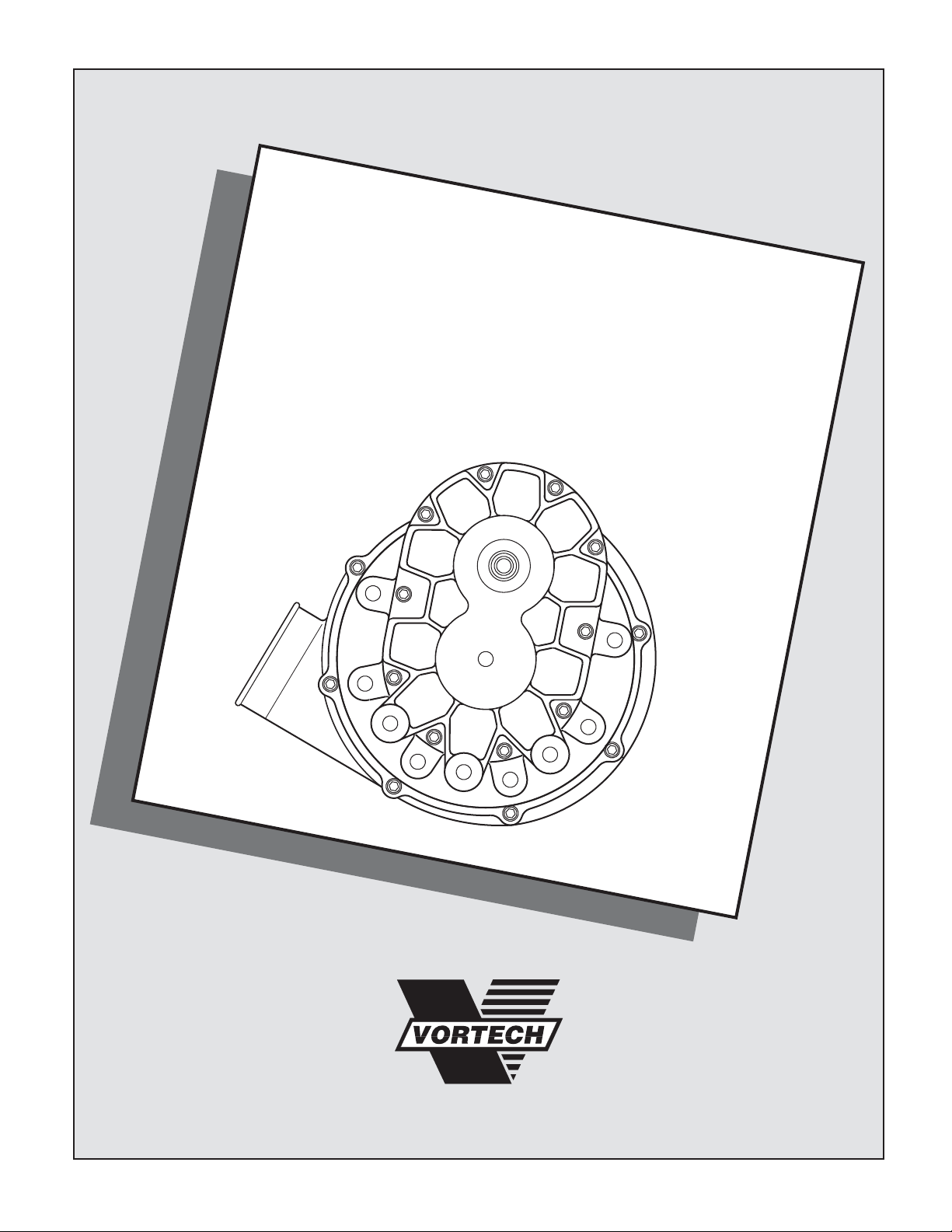
A. Remove the ducting between the air box and
the throttle body. Disconnect the MAF from
the ducting and set aside.
B. Remove the air box, fresh air tube, battery,
battery box and all remaining components
running to the inlet of the motor.
C. Remove the Battery/Air Box support bracket:
1. Support the driver’s side of the transmis-
sion.
2. Remove four nuts securing the bracket to
the driver’s side engine mount.
3. Remove the large central nut securing
the transmission to the engine mount.
4. Lift the plate on top of the engine mount
and remove the Battery/Air Box support
bracket.(See Fig. 1-a.)
5. Reinstall the engine mount plate and
resecure all engine mount hardware.
D. Place an oil drain pan beneath the power
steering pump. Disconnect the high-pressure
(3/8" tube) power steering line from the power
steering pump. Disconnect the opposite end
of the power steering line from the steering
rack. Disconnect all other suppor ts securing
the power steering line and remove it from
the car.
E. From under the vehicle, remove the plastic
cover protecting the belts and pulleys.
F. From under the vehicle, release the tension
on the accessory drive belt and remove the
drive belt.
G. Disconnect the fill hose from the power steer-
ing pump.Remove the four screws securing
the power steering pump and remove the
power steering pump from the vehicle.
H. Drain sufficient coolant to remove and relo-
cate the plastic upper coolant manifold located near the upper radiator core support. (See
Fig. 4-c.)
I. ZX3 Only: Remove the four screws securing
the heat shield to the header.Remove the
heat shield.
J. Locate the PCV valve located near the dri-
ver’s side of the exhaust manifold on the front
of the engine. Pull the stock PCV valve and
install the supplied PCV valve in its place.
K. Remove the screws and pushpins securing
the front bumper cover. Remove the front
bumper cover from the car.
1. PREPARATION/REMOVAL
Fig. 1-a
BATTERY/AIRBOX SUPPORT
TO REMOVE
NOTE: - ZX3 Models Only
1. Remove the passenger side front kick panel from the interior of the vehicle. Remove the sound deadening
material (if any) that is covering the ECM. Remove the plastic ECM hold-down bracket.
2. Using a 10mm socket or wrench, remove the harness and plug from the ECM (as you loosen the bolt, the
connector will slowly release). Remove the ECM from the vehicle.
3. Contact the Vortech Service Department for a Return Authorization Number. Send both ECM and supplied
credit tag to Vortech using the enclosed shipping box.
Page 14
P/N: 4FJ020-010
©2004 Vortech Engineering, LLC
All Rights Reserved, Intl. Copr.Secured
19APR04 v3.0 Focus(4FJ v3.0)
2
A. Disconnect the connectors attached to the
oxygen sensors on the catalytic converter
assembly.
B. Unsecure all hardware and brackets securing
the catalytic converter.
C. Disconnect the EGR tube where it connects
to the EGR control valve toward the rear of
the engine.
D. Manipulate the catalytic converter to either
side to get a clear view of the oil drain location.
E. To provide an oil drain for the supercharger, it
is necessary to make a drain hole in the
engine block skirt. Locate and center-punch
the hole in the exact location as shown per
Figs. 2-a, 2-b.Drill a 1/8" pilot hole at the
center location.
F. Use the supplied 9/16" rotobroach to drill the
hole.Take care to break through the pan and
gently remove the cut out.
G. Pack the flutes of a 3/8" NPT tap with grease.
Tap the hole until the fitting can be star ted.
H. Thoroughly clean the threaded area. Reach
inside the oil pan and retrieve any stray chips.
I. Apply a small amount of sealer to the threads
of the supplied 3/8" NPT hex nipple and
secure in the new hole.Make sure that a seal
is formed around the fitting. (See Fig. 2-a.)
J. Apply sealant to the opposite side of the fit-
ting and install the supplied 3/8" x 90° fitting
on the end of the hex nipple.
K. Apply sealant to the threaded end of the sup-
plied 3/8" x 1/2" barb fitting. Install this fitting
into the 90° fitting. Orient the fittings to point
upward towards the driver’s side. (See Fig.
2-a.)
L. (ZX3 Models Only) Resecure the catalytic
converter and all brackets back to stock location, reconnect the EGR line back to the EGR
control valve. Reconnect the oxygen sensors
and reinstall the heat shield.
2. SUPERCHARGER OIL DRAIN (SVT Models skip steps A-D and proceed to Step E.)
Fig. 2-a / ZX3 Oil Drain
OIL DRAIN ROUTED
BEHIND CAT BRACKET
Fig. 2-b / Oil Drain Hole
Fig. 2-c / SVT Oil Drain
NOTE: SVT Models - It will be necessary to
either loosen the exhaust header or
shorten the supplied rotabroach .33" to
get sufficient room for drilling the oil
drain.
Page 15

P/N: 4FJ020-010
©2004 Vortech Engineering, LLC
All Rights Reserved, Intl. Copr.Secured
19APR04 v3.0 Focus(4FJ v3.0)
3
A. Locate the oil pressure sender on the back of
the engine block near the oil filter. Remove
the oil pressure sender.
B. Lightly lubr icate the threads of the supplied
1/8" NPT street fitting with engine oil. Install
the street fitting into the block.
C. Install the oil pressure sender into the street
fitting so that it is pointing upward and parallel
with the egine block.
D. Install the 1/8" NPT to -4 fitting into the end of
the street fitting so that it is perpendicular to
the engine block.(See Fig. 3-a.)
E. Install the 90° end of the feed hose to the -4
fitting and route it close to the block and up to
the supercharger mounting location.
F. Install the electronic plug back onto the oil
pressure sender.
3. SUPERCHARGER OIL FEED
Fig. 3-a
A. Locate the coolant manifold running across
the top/front of the radiator support. Remove
the plastic manifold and disconnect the three
coolant lines running to the manifold. (See
Fig. 4-c.)
B. Cut 1" off the end of each coolant line r un-
ning to the manifold.
C. Modify the plastic coolant manifold by grind-
ing both tabs so that they are flush with the
manifold. (See Fig. 4-a.)
D. Reattach the lines to their original manifold
ports. (Cutting the lines allows for the coolant
manifold to sit lower.)
E. Tuck the manifold between the top of the radi-
ator and the upper radiator support. This will
allow for clearance between the drive assembly and the coolant manifold.(See Fig. 4-b.)
4. CROSSOVER COOLANT LINE MODIFICATION
Fig. 4-a
Fig. 4-b
Fig. 4-c
1/8"NPT TO -
4 FITTING
STREET
FITTING
2 AREAS TO GRIND
COOLANT MANIFOLD
IN RELOCATED
POSITION
STOCK COOLANT
MANIFOLD LOCATION
Page 16

P/N: 4FJ020-010
©2004 Vortech Engineering, LLC
All Rights Reserved, Intl. Copr.Secured
19APR04 v3.0 Focus(4FJ v3.0)
4
A. Locate the supplied power steering relocation
block.Install the two supplied alignment dowels into the back side of the block.(See Fig.
5-a.)
B. Locate the factory hose clamp secur ing the
lower radiator hose.Orient the clamp to give
clearance for the P/S relocation block.
C. Install the supplied power steering relocation
block onto the cast power steering mounting
bracket that the pump originally mounted to.
Make sure the alignment dowels align with
their corresponding holes on the stock bracket.
D. Use the four supplied 8mm x 1.0" x 40mm
SHCS and 8mm washers to secure the relocation block to the stock bracket.
E. Install the secondar y mounting plate to the
three hole pattern on the side of the relocation block with the supplied 3/8"-18 x 1" flathead screws.(See Fig. 5-b.) Tighten the 3/8"
screws.
F. Place the power steering pump against the
installed relocation block.Make sure that the
stock alignment dowels are installed into the
back of the power steering pump. Secure the
pump to the lower set of four holes in the
relocation block using the stock hardware.
5. POWER STEERING RELOCATION/SECONDARY PLATE INSTALLATION
Fig. 5-a
Fig. 5-b
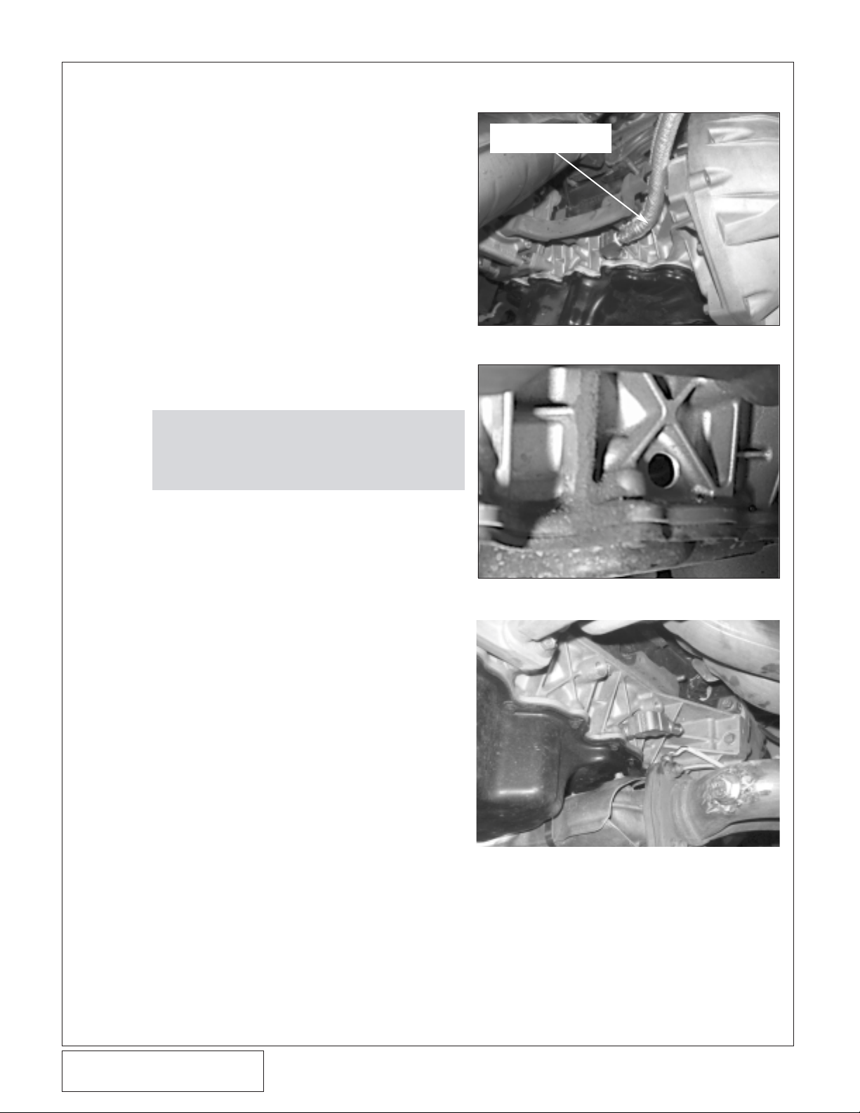
A. Cut the previously removed high-pressure
power steering line in two places.
• The first cut is directly after the long rubber section of power steering line. Cut
the hard line leaving the maxumum
amount of straight section connected to
the rubber end. (See Fig 6-a, 6-c.)
• The second cut through the hard line will
be on the pump side. Cut the line so that
the maximum section of straight tube
remains with the fitting that connects to
the power steering pump.(ZX3 Models
refer to Figs.6-b,6-d.) (SVT Models:
refer to Figs.6-f, 6-g.)
6. POWER STEERING LINE MODIFICATION
Fig. 6-a
Fig. 6-b / ZX3 Models Only
NOTE: It is necessar y when cutting the power
steering lines that the cuts are straight and
clean. It will be necessary to remove the
paint on the lines before installing the compression fittings. Do not “grind” the paint
off of the lines as that will reduce the diameter of the line so that the new fitting may
not properly function.
INSTALLED ALIGNMENT DOWELS
P/S PUMP
REINSTALLED
SECONDARY MOUNTING
PLATE INSTALLED ON P/S
RELOCATION BLOCK
LOCATION TO MAKE CUT.
LEAVE THE MAXIMUM
AMOUNT OF STRAIGHT
SECTION POSSIBLE
END ATTACHES
TO P/S PUMP
LOCATION TO MAKE
CUT. LEAVE THE MAX-
IMUM AMOUNT OF
STRAIGHT SECTION
ALLOWABLE
POWER STEERING
FITTING TO KEEP
END ATTACHES
TO STEERING
RACK
KEEP THIS
SECTION
NOTE: When installing the compression fitting,
initially tighten the fitting finger tight.
Using wrenches, continue 1-1/2 turns so
that the fitting is secure.
Page 17

P/N: 4FJ020-010
©2004 Vortech Engineering, LLC
All Rights Reserved, Intl. Copr.Secured
19APR04 v3.0 Focus(4FJ v3.0)
5
B. Install the compression fitting with the
3/8"NPT female outlet on the shortest section
of power steering line containing the fitting
that connects to the power steering pump.
(ZX3 Models: see Fig. 6-d, SVT Models: see
Fig. 6-g.)
C. Install the compression fitting with the
1/4"NPT female outlet on the longer section
of power steering hose. (Both models see
Fig. 6-c.)
D. Install the 3/8"NPT x -6 x 45° fitting into the
3/8"NPT female outlet installed on the short
section of power steering line.Take this
assembly and install it into the bottom of the
power steering pump with the 45° fitting
pointing toward the front of the car. (ZX3
Models see Fig. 6-e, SVT Models see Fig.
6-h.)
E. Install the 1/4 NPT x -6 fitting into the 1/4
NPT female outlet installed on the long section of the power steering line. Reinstall the
stock section of the power steering line back
into the steering rack. Route the open end of
the hose, in its stock location orienting it
toward the front of the car.
6. POWER STEERING LINE MODIFICATION, cont’d
Fig. 6-d / ZX3 Models Only
Fig. 6-e / ZX3 Models Only
Fig. 6-c
COMPRESSION FITTING
COMPRESSION
FITTING
STOCK P/S PUMP
FITTING REMOVED
IN FIG. 6-b
3/8NPT X -6
x 45° FITTING
1/4"NPT x -6 FITTING
COMING FROM P/S RACK SIDE
FITTING ASSEMBLY
DIRECTLY OFF THE
POWER STEERING PUMP
SECURED P/S HOSE
Fig. 6-f / SVT Models Only
CUT
Fig. 6-g / SVT Models Only
CUT SECTION w/FITTINGS
INSTALLED
STOCK, UNCUT P/S HOSE
Page 18

P/N: 4FJ020-010
©2004 Vortech Engineering, LLC
All Rights Reserved, Intl. Copr.Secured
19APR04 v3.0 Focus(4FJ v3.0)
6
A. Remove the three upper, forward most
screws from the bell housing. (See Fig.8-a.)
B. Slide the supplied heat shrouding over the
1/2" fabric braid oil drain hose.Attach the oil
drain hose to the supercharger drain fitting
and tighten the supplied #8 hose clamp.
C. Install the supplied Ø5/16" x 1.00" dowel into
the countersunk holes in the supercharger
gear case. (See Fig.8-b.)
8. DRIVE SHAFT AND SUPERCHARGER INSTALLATION
A. Disconnect the four (4) fuel injector wiring
clips and retainers from the fuel injectors.
Release any residual fuel pressure from the
rail by opening the schrader valve on the rail.
Have a fire extinguisher nearby and use
extreme caution.
B. Remove the bolts holding down the factory
fuel rail onto the intake manifold.Lift up on to
the rails evenly, removing all four injectors.
C. Using a small amount of clean motor oil,
lightly lubricate the O-rings on both ends on
the Vor tech supplied fuel injectors.
D. Install the new injectors into the fuel rails with
the terminals facing outward.
7. FUEL INJECTOR REPLACEMENT
NOTE: Make sure injectors are secure and
properly installed. Re-check after
cycling fuel system.
E. Carefully lower the fuel rail/injector
assembly down onto the intake
manifold. Check to see that each
injector has been seated properly
into the manifold.
F. Tighten down the fuel rail assem-
bly with the original bolts and
attach the wiring clips to the injector terminals.
F. Connect both ends of the open hose with the
supplied high-pressure line. ZX3 Models:
Route the hose from the 45° fitting pointing
off the P/S pump to the bottom/rear of the
radiator, over the air filter, along the drivers
side frame rail over to the long section of
power steering hose. (See Figs. 6-e, 9-b.)
SVT Model: Route the supplied hose from
the 45° fitting in front of the radiator over to
the driver’s side, over the air filter, along the
driver’s side frame rail to the installed stock
P/S hose section. (See Figs.6-h, 6-i.)
Fig. 6-h / SVT Models Fig. 6-i / SVT Models
G. Use adel clamps to keep the high-
pressure line secure. (See Figs. 6-
e, 9-b.)
H. Using the supplied 5/8" hose-
mender and length of hose,
lengthen the power steering fill
hose. Secure it away from the
supercharger pulley.
I. Refill the power steering reservoir.
FITTING POINTING DOWN
TOWARD THE FRONT OF CAR
SUPPLIED P/S HOSE ROUTED
IN FRONT OF THE RADIATOR
SUPPLIED P/S LINE
ROUTED OVER THE AIR
FILTER TO THE DRIVER’S
SIDE FRAME RAIL
6. POWER STEERING LINE MODIFICATION, cont’d
Page 19

P/N: 4FJ020-010
©2004 Vortech Engineering, LLC
All Rights Reserved, Intl. Copr.Secured
19APR04 v3.0 Focus(4FJ v3.0)
7
D. Install the supercharger mounting plate on
the alignment dowels and tap the plate lightly
until it is flush with the supercharger gear
case. (See Fig. 8-b.)
E. Align the counter bores in the black coupler
housing with the alignment dowels passing
through the supercharger mounting plate.
Lightly tap the drive housing until it is flush
with the mounting plate. (See Fig.8-c.)
F. Install onto the supercharger input shaft, the
supplied key and drive coupling containing
three 1/4" diameter dowel pins protruding
from it. (Apply a thin film of anti-seize or
grease onto the inside diameter of the coupling before installing onto the input shaft.)
Secure the coupling with the supplied 3/8"-24
x .75" HXHD and Ø1.0 O.D. washer.
8. DRIVE SHAFT AND SUPERCHARGER INSTALLATION, Cont’d,
Fig. 8-a
Fig. 8-b
Fig. 8-c
Fig. 8-d
NOTE: Heat may also be necessary to install the
coupling onto the shaft. (A propane
torch will make this easier if needed.)
Use a light thread lock compound on the
3/8"-24 x .75" screw threads.
NOTE: It is necessary to leave the hardware
loose to allow for the correct clocking of
the housing assembly upon final installation. (See Fig. 8-d.)
G. Install the two supplied 1.80" spacers
between the supercharger and the mounting
plate. Secure in one location with a 3/8"-16 x
2.5" flathead and in the other with a 2.75"
HXHD. Leave both fasteners loose at this
time. (See Fig. 8-c.)
H. In the middle mounting location, secure the
supercharger to the mounting plate with the
supplied 12mm x 1.75" x 25mm screw and
washer. Leave the fastener loose at this time.
(See Fig. 8-c.)
I. Locate the preassembled drive shaft assem-
bly. Connect the three-pin coupler from the
end of the drive shaft to the three-pin coupler
on the supercharger assembly using the supplied composite ring. Align the hole patterns
so that one side of pins is alternating with the
opposite side of pins. Each pin will have its
own hole.Verify that each set of pins is
inserted into the raised bosses with holes
on their corresponding side of the composite ring. Push together until each coupler
is flush with the composite ring. (See Figs. 8d and the boxed section of Fig 8-f.)
J. With the couplers aligned, align the two cou-
pler housings. Using the four 5/16"-18 x 5.25"
HXHD screws secure the drive shaft assembly to the supercharger assembly.
K. Lower the supercharger and drive assembly
12mm x 1.25 x 25mm
1.8" SPACER
0.630 O.D.
SPACER LOCATION
INSTALLED
Ø5/16" DOWELS
INSTALLED DRIVE
COUPLING
COUPLER HOUSING
LEAVE LOOSE
UNTIL STEP O
3 LOCATIONS TO
REMOVE STOCK
HARDWARE
Page 20

P/N: 4FJ020-010
©2004 Vortech Engineering, LLC
All Rights Reserved, Intl. Copr.Secured
19APR04 v3.0 Focus(4FJ v3.0)
8
into position locating where the exhaust manifold heat shield and drive shaft will come into
contact. (See Fig. 8-e.)
L. ZX3 Models Only: Mark the heat shield,
remove the drive assembly and modify the
heat shield to clear the drive assembly. (See
Fig. 8-e.) Using an oversize tube or dowel to
form the heat shield is the easiest method for
modification. (See Fig. 8-g.)
M. Place the drive assembly back into position.
Loosely install the 10mm x 140mm screws
and 3.56" spacers between the supercharger
mounting plate and the bell housing locations.
The Ø.630 O.D. spacer will be placed in the
forward most, bottom position on the bell
housing. (See Figs. 8-a., Fig. 8-f.)
N. Loosely install the four 5/16"-18 x .75" flat-
head screws through the secondary mounting
plate into the bearing housing. (See Fig. 8-f.)
O. Tighten all the drive fasteners in the following
order:
•Four 5/16"-18 x .75" flathead screws connecting the bearing housing to the secondary plate
8. DRIVE SHAFT AND SUPERCHARGER INSTALLATION, cont’d
Fig. 8-e
Fig. 8-f
AREA TO MODIFY
Fig. 8-g
AREA TO MODIFY
4 x 5/16"-18 x .75" FLATHEADS
4 x 5/16"-18 x 1.00" HXHD
4 x 5/16"-18 x 5.25" HXHD
DRIVE COUPLING HOUSING
DRIVE COUPLINGS
COMPOSITE DISK
DRIVE COUPLINGS
Ø.875" x 3.56" SPACER
Ø.630" x 3.56"
SPACER
10mm x 140mm HARDWARE
Page 21

P/N: 4FJ020-010
©2004 Vortech Engineering, LLC
All Rights Reserved, Intl. Copr.Secured
19APR04 v3.0 Focus(4FJ v3.0)
9
8. DRIVE SHAFT AND SUPERCHARGER INSTALLATION, cont’d
Fig. 8-g
Fig. 8-h
R. Install the dr ive belt. It may be
necessary to loosen one of
the idlers to get the belt on
due to tight clearances. (See
Figs. 8-h, 8-i.)
S. Install the oil feed and oil drain
hoses.
NOTE: Blue Loctite is recom-
mended on the 7/16"
screws.
•Four 5/16"-18 x 5.25" HXHD screws connecting the shaft housing and coupler
housing to the supercharger and mounting plate
•Four 5/16"-18 x 1.00" HXHD screws connecting the bearing housing to the shaft
housing
• The 3/8"-16 x 2.5" flathead, 3/8"-16 x
2.75" HXHD and 12mm x 1.75 x 25mm
HXHD securing the supercharger directly
to the mounting plate
• Three 10mm x 1.5 x 140mm HXHD
screws securing the mounting bracket
and 3.56" spacers to the bell housing
P. Lightly grease the extended supercharger
input shaft. Install the key and supercharger
pulley oriented so that the long snout of the
pulley is facing toward the supercharger.
Secure the pulley with a 3/8"-24 x 1.0" HXHD,
3/8" washer and pulley retainer.
Q. Install two supplied 2.5" aluminum idlers
using 7/16"-18 x 1.5" hardware, pulley retainers and idler spacers.The idler retainers
(.220" THK) go between the pulley and the
7/16" screw and spacers (.416" THK) are
placed between the idlers and the secondary
mounting plate. When the pulleys are
installed the snap ring retaining the bearing should be facing away from the
mounting plate. (See Fig. 8-h.)
NOTE: Blue Loctite is recommended on the
3/8"-24 x 1.00" screws.
INSTALLED IDLER PULLEY
Fig. 8-i / Belt Routing
STOCK
IDLER
SUPPLIED
2.5"
IDLERS
VORTECH SUPPLIED IDLER
IDLER RETAINER
IDLER SPACER
SECONDARY
MOUNTING
PLATE
ALT
TENSIONER
.220 THICK
7/16-18 x 1.5" SCREW
WATER
PUMP
CRANK
PULLEY
.416
THICK
A/C
S/C
PULLEY
POWER
STEERING
Page 22

P/N: 4FJ020-010
©2004 Vortech Engineering, LLC
All Rights Reserved, Intl. Copr.Secured
19APR04 v3.0 Focus(4FJ v3.0)
10
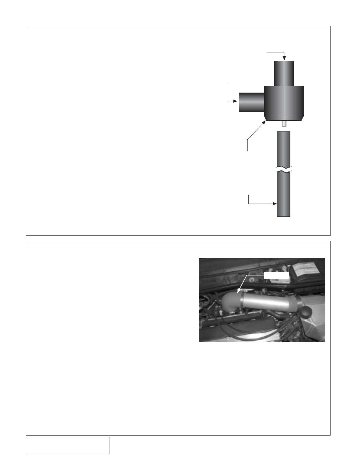
9. AIR INLET ASSEMBLY
Fig. 9-a
Fig. 9-b
A. Unplug the electr ical connector from the hor n.
Remove the horn from the car.
B. Install into the 3/4"NPT boss of the 90° roto-
mold duct the supplied straight 1" barb.(See
Fig. 9-a.)
C. Install into the 3/8"NPT boss of the rotomold
duct the supplied 5/8" barb x 90°.
D. Connect the Ø3.5" end of the 90° inlet duct to
the inlet of the supercharger using the supplied Ø3.5" x 2" sleeve and #56 hose clamps.
Orient the duct so that the open end is pointing down. (See Fig.9-a.)
E. Connect the length of 3" flex-hose to the
open end of the 90° duct using a #48 hose
clamp.
F. Connect the MAF sensor to the supplied
bracket.(See Fig. 9-c.) Attach the supplied air
filter to the inlet of the MAF. (See Fig. 9-d.)
G. Set the air filter/MAF assembly on the lower
radiator support where the horn was located.
Mark two locations and drill using a 9/32"
drill. Secure using the supplied 1/4" hardware. (See Fig. 9-b.)
I. ZX3 Models: (See Fig. 9-e) cut all six (6)
wires leading to the MAF plug leaving 3"-4"
before the plug. Using the supplied wires and
butt connectors extend all six wires so that
they reach the new MAF location.
SVT Models: Cut the middle four wires leaving 3" to 4" after the MAF plug. Cut the outer
2 wires leaving the longest amount of wire
attached to the plug. Extend the four middle
wires so that the MAF plug can reach the
relocated sensor.Connect the white with purple stripe wire to the red wire on the supplied
IAT sensor har ness. Connect the black with
white stripe wire to the brown/black wire on
the IAT sensor. (See Fig. 9-e.) Trim the long
outer wires left on the MAF plug leaving only
a couple of inches of wiring coming out of the
plug.
3/4"NPT TO 1" BARB
3/8"NPT TO 5/16" BARB
MAF AND BRACKET MOUNTING LOCATION
P/S HOSE SECURED
Fig. 9-c
VORTECH SUPPLIED BRACKET
NOTE: Soldering the wire extension is pre-
ferred. Shrink sleeve has been supplied
to seal the solder joints.
J. Re-attach MAF plug to MAF meter.
K. Reinstall the factory hor n as shown in Fig. 9-f
using the supplied 6mm screw.
Page 23

P/N: 4FJ020-010
©2004 Vortech Engineering, LLC
All Rights Reserved, Intl. Copr.Secured
19APR04 v3.0 Focus(4FJ v3.0)
11
Fig. 9-d
Fig. 9-f
Fig. 9-e / MAF Plug Modifications
9. AIR INLET ASSEMBLY, cont’d
NEW HORN LOCATION
BLACK w/ORANGE STRIPE
GREEN w/RED STRIPE
(SVT ONLY)-WHITE w/PURPLE
STRIPE CONNECT TO THE RED
AIR TEMP SENSOR WIRE
(ZX3 ONLY)-EXTEND WIRE TO
MAF PLUG (ALL 6 WIRES)
RED
BLACK/BROWN
SUPPLIED IAT SENSOR CONNECTOR
(SVT MODELS ONLY)
BROWN w/BLUE STRIPE
WHITE w/BLUE STRIPE
(SVT ONLY)-BLACK w/WHITE
STRIPE CONNECT TO THE BROWN
AIR TEMP SENSOR WIRE
(ZX3 ONLY)-EXTEND WIRE TO
MAF PLUG (ALL 6 WIRES)
WIRING EXTENSIONS
EXTEND WIRES TO THE MAF
NEW LOCATION
(SVT ONLY)
WIRING NO LONGER
ATTACHED TO MAF PLUG
MAF PLUG
Page 24

P/N: 4FJ020-010
©2004 Vortech Engineering, LLC
All Rights Reserved, Intl. Copr.Secured
19APR04 v3.0 Focus(4FJ v3.0)
12
10. SVT DSI BOX RELOCATION
A. Locate the DSI Box in the driver’s side fender
well. Disconnect the electrical connector from
the box. Disconnect the cable from the base
of the throttle body. (See Figs.10-a, 10-b.)
B. Remove the hardware securing the DSI box
bracket from the frame rail. Remove the box
from the bracket.
C. Using two of the original batter y tray hold
down screws, secure the supplied DSI box
relocation bracket to the top of the driver’s
side frame rail (See Fig. 10-c.).
D. Secure the DSI box to the relocation bracket
using the supplied 1/4-20 hardware. (See Fig.
10-d.)
E. Reconnect the electrical connector to the DSI
box. Route the cable back to the base of the
throttle body and reconnect. (Ensure that the
cable has no kinks and has free movement.)
Fig. 10-a / SVT Model Only
Fig. 10-b / SVT Model Only
Fig. 10-c / SVT Model Only
Fig. 10-d / SVT Model Only
UNSNAP LINE
BRACKET INSTALLED
DSI BOX INSTALLED
Page 25

P/N: 4FJ020-010
©2004 Vortech Engineering, LLC
All Rights Reserved, Intl. Copr.Secured
19APR04 v3.0 Focus(4FJ v3.0)
13
11. STANDARD DISCHARGE INSTALLATION (H.O. Charge-cooled applications skip to
Section 12.)
Fig. 11-a / (SVT Model)
A. Install the 2.75" to 2.5" reducer sleeve onto
the supercharger discharge.
B. Install on the throttle body the supplied 90°
silicone sleeve.
• ZX3 Models: Use the Ø3.25 x Ø2.75" x 90°
sleeve on the throttle body. (See Fig. 11-b.)
• SVT Models: Use the Ø2.75" x 90° sleeve
on the throttle body. (See Fig.11-a.) Inser t
the supplied rubber grommet and IAT sensor
into the discharge tube. Lubricate for easier
fit if needed.
C. Between the two installed sleeves install the
Vortech discharge tube:
D. ZX3 Models: Secure the sleeve on the throt-
tle body with the supplied #44 and # 48 hose
clamps. Secure the sleeve on the supercharger with the supplied #44 and #40 hose
clamps. (See Fig. 11-b.)
SVT Models: Secure the sleeve on the throttle body with the supplied #44 hose clamps.
Secure the sleeve on the supercharger side
with the supplied #44 and #40 hose clamps.
(See Fig. 11-a.) Connect the recently
installed IAT sensor har ness to the IAT sensor in the discharge tube.
E. Connect the supplied 5" piece of Ø1.0" hose
to the barb on the discharge duct.
F. Using the supplied #16 hose clamps, connect
the inlet of the bypass to the open end of the
installed hose.
G. Using the supplied #16 hose clamps and 90°
molded hose, connect the opposite end of the
bypass valve to the Ø1.0" barb installed on
the inlet duct. (See Figs.11-c, 11-d.)
Trimming of the rubber 1" elbow may be
required.
H. Using the supplied 5/32" TEE and vacuum
hose connect the bypass valve to an engine
vacuum source.(See Fig. 11-d.)
NOTE: Make sure that the vacuum barb on the
bypass valve is installed so that it is
pointing down, directly away from the
discharge tube
Fig. 11-b / (ZX3 Model)
Fig. 11-c / (ZX3 Model)
90° MOLDED HOSE
BYPASS VALVE
Page 26
P/N: 4FJ020-010
©2004 Vortech Engineering, LLC
All Rights Reserved, Intl. Copr.Secured
19APR04 v3.0 Focus(4FJ v3.0)
14
11. STANDARD DISCHARGE INSTALLATION, cont’d (H.O. Charge-cooled applications skip
to Section 12.)
Fig. 11-d
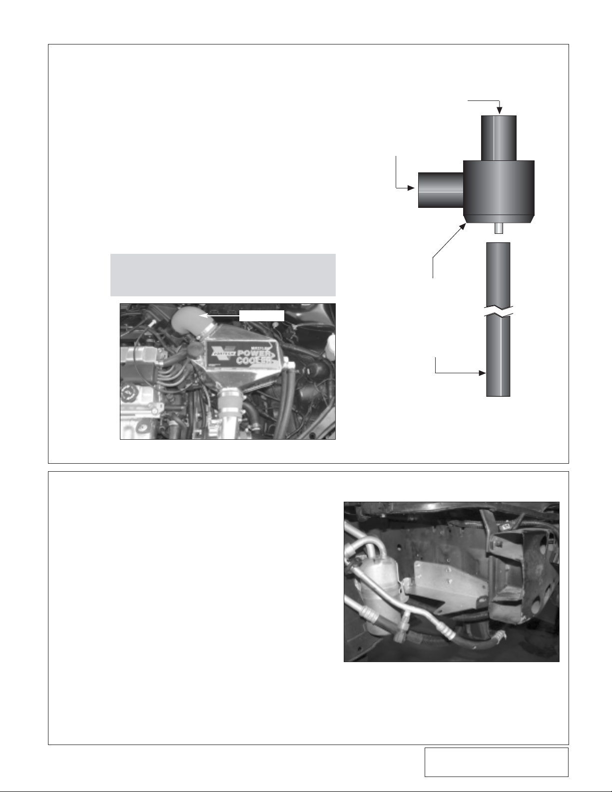
12. CHARGE COOLED DISCHARGE INSTALLATION
Fig. 12-a / ZX3 Model
90° ELBOW
A. Install on the supercharger discharge the
Ø2.75" to 2.5" reducer sleeve.
B. Install the supplied 90° sleeve on the throttle
body.
• ZX3 Models: Ø3.25" to 2.75" reducer x 90°
• SVT Models: Ø2.75" x 90° sleeve.
C. Install the welded charge-cooler into the
Ø2.75" end of the reducer sleeve on the discharge of the supercharger.
ZX3 Models: Install the Ø2.75" x 2.0" sleeve
on the discharge side of the charge cooler.Install the supplied discharge tube
between the charge cooler and the 90°
sleeve on the throttle body. Secure the
discharge tube with #44 hose clamps.
(See Fig. 12-a.)
SVT Models: Connect the discharge of the
charge cooler to the throttle body with
the installed 90° elbow and #44 hose
clamps. (See Fig. 12-b.) Insert the supplied rubber grommet and IAT sensor
into the discharge tube. Lubricate for
easier fit if needed. Connect the recently
installed IAT sensor har ness to the IAT
sensor in the discharge tube.
SUPERCHARGER
DISCHARGE TUBE
AIR INLET
DUCT
BYPASS VALVE
5/32” HOSE
Page 27
P/N: 4FJ020-010
©2004 Vortech Engineering, LLC
All Rights Reserved, Intl. Copr.Secured
19APR04 v3.0 Focus(4FJ v3.0)
15
12. CHARGE COOLED DISCHARGE INSTALLATION
Fig. 12-b / SVT Model
Fig. 12-c
D. Connect the supplied 5" piece of Ø1.0" hose
to the barb on the bottom of the charge cooler.
E. Using the supplied #16 hose clamps, connect
the inlet of the bypass to the open end of the
installed hose.
F. Using the supplied #16 hose clamps and 90°
molded hose, connect the open end of the
bypass valve to the Ø1.0" barb installed on
the inlet duct. (See Fig. 12-a.) Tr imming of the
1" rubber elbow may be required.
G. Using the supplied 5/32" TEE and vacuum
hose connect the bypass valve to an engine
vacuum source.(See Fig. 12-c.)
NOTE: Make sure that the vacuum barb on the
bypass valve is installed so that it is
pointing down and away from the discharge.
13. WATER TANK AND WATER PUMP INSTALLATION (H.O. Charged Cooled Kits Only.)
A. Unsnap the A/C line from the driver’s side
frame rail bracket, then remove the bracket.
B. Align the supplied bracket with the bottom of
the passenger’s side framerail (See Fig. 13-a.)
C. Locate and mark locations to mount the water
tank bracket in the passenger’s side fenderwell. (See Fig. 13-a.)
D. Using the supplied sheet metal screws, mount
the water tank bracket. (See Fig. 13-a.)
E. Using the #28 adel clamp and 1/4"-20 hard-
ware, secure the water pump to the inside of
the water tank as shown.(See Fig. 13-b,
13-d.)
F. Install the 1/2"NPT x 90° brass fittings in the
top and bottom of the tank. Install the Ø3/4" x
90° molded hose between the inlet of the
water pump and the bottom 90° fitting. (See
Fig. 13-d.)
G. Install into the 1"NPT hole in the top of the
water tank the supplied aluminum bushing.
Leave the 1/8"NPT pipe plug out until you
have completely filled the system.
90° ELBOW
Fig. 13-a
SUPERCHARGER
DISCHARGE TUBE
AIR INLET
DUCT
BYPASS VALVE
5/32” HOSE
Page 28

P/N: 4FJ020-010
©2004 Vortech Engineering, LLC
All Rights Reserved, Intl. Copr.Secured
19APR04 v3.0 Focus(4FJ v3.0)
16
13. WATER TANK AND WATER PUMP INSTALLATION (H.O. Charged Cooled Kits
Only.), cont’d
Fig. 13-b
Fig. 13-c
Fig. 13-e
Fig. 13-d
H. Install the water tank assembly into the
mounted bracket securing the tank in three
locations with 1/4"-20 x .5" hardware.Point
the upper 90° fitting so that it is pointing at
the driver’s side. (See Fig. 13-b.)
I. Gently bend the A/C line with the pressure
sensor up so the wiring harness will reach.
(See Fig. 13-f.)
J. Mount the supplied water pump relay near the
firewall just below the fuse box. (See Fig.
13-c.)
K. Connect the red 12-gauge wire from terminal
#30 to the supplied fuse holder using the supplied butt connector. Install a yellow ring terminal on the other end of the fuse holder and
bolt to a positive power supply.
L. Feed the yellow wire from relay terminal #85
to the fuse box on the driver’s side of the
engine bay. Route the wire to the D1 engine
fuse and using the supplied fuse tap connect
the yellow wire to the fuse.
M. Run the black wire from terminal #86 on the
relay to a clean ground.
N. With the long red 12-gauge wire connected to
the water pump relay terminal #87, route the
free end across the firewall, along the fender
and down to the water pump. Secure as necessary to avoid heat and sharp edges.
O. Cut the stock electrical plug off the water
pump.Connect the blue/green positive wire on
the water pump to the positive red wire with
the supplied slide connectors.
P. Run the brown negative wire to a clean
ground.
WATER PUMP RELAY
WATER PUMP
1/2" NPT x 90°
FITTINGS
LIGHTLY BEND A/C LINE UP TO
REACH THE WIRING HARNESS
Fig. 13-f
MODIFIED A/C LINE
GROUND
RELAY
87
86
87A
30
(+) WATER
PUMP
85
D-1 ENGINE
FUSE
(+) BATTERY
TERMINAL
Page 29

P/N: 4FJ020-010
©2004 Vortech Engineering, LLC
All Rights Reserved, Intl. Copr.Secured
19APR04 v3.0 Focus(4FJ v3.0)
17
14. HEAT EXCHANGER MOUNTING (H.O.Charged Cooled Kits Only.)
Fig. 14-a
Fig. 14-b
A. Un-secure the power steering cooler from the
front of the car.Drill 9/32" holes in the rear of
the mounting tabs.
B. Remount the power steering cooler using the
new holes to position it forward.
C. Mar k locations for the supplied water cooler.
D. Mount the supplied cooler using the supplied
self tapping screws with the barbs facing to
the driver’s side directly behind the remounted power steering cooler.(See Fig. 14-a.)
15. WATER LINE ROUTING (H.O.Charged Cooled Kits Only.)
A. Cut a 60" length of 3/4" hose. Run this
from the top 90° fitting on the charge
cooler to the 90° fitting located on the
top of the triangular water reservoir.
Route the hose towards the front of the
car between the air conditioning condenser and grill, over to the water tank.
Make sure that the hose is smoothly
routed without tight bends or kinks.
B. Install the 4" end of the 90° molded
rubber elbow to the outlet of the water
pump.
C. Cut a 70" length of 3/4" hose. Connect
it to the 12" end of the 90° molded
hose with the supplied barbed hose
mender.Run the hose along the base
of the radiator to the supplied rubber
180° hose using the 3/4"-5/8" reducer.
Run the open end of the 180° hose to
the bottom barb on the water cooler
(Running this hose to the bottom barb
is important to flush out any air in the
water system.)
NOTE: When routing hoses, refer to Fig. 15-a.
Trim all hoses for best fit.
D. Cut a 40" length of 3/4" hose. Run this
from the top barb of the water cooler to
the bottom 90° fitting on the charge air
cooler.
E. Secure all hose ends with the supplied
nylon clamps.
F. Start filling the system with a 50/50
water/glycol mix. Check the 1"NPT aluminum fitting in the water tank to see if
water is flowing out of the 1/8"NPT
hole. Once water is to this point, install
the 1/8"NPT plug into the 1” aluminum
fitting.
G. With the key on, make sure the charge
cooler water pump is operating and
that water is flowing through the cooler.
Fill the system if necessary. If the
water is not flowing, remove the charge
cooler supply hose and lower until
water flow out of the hose. If necessary, provide light suction to the hose
to help prime the pump.Verify water
flow. Do not let the pump run for
extended periods (30 seconds or
more) without water flow. Fill the
charge cooler tank until the level stabilizes.
POWER STEERING COOLER
MOUNTED FORWARD
DRILL NEW Ø.28" MOUNTING HOLES
IN THIS POSITION
1.25"
EXISTING HOLES
BOTTOM VIEW
POWER STEERING COOLER
Page 30
P/N: 4FJ020-010
©2004 Vortech Engineering, LLC
All Rights Reserved, Intl. Copr.Secured
19APR04 v3.0 Focus(4FJ v3.0)
18
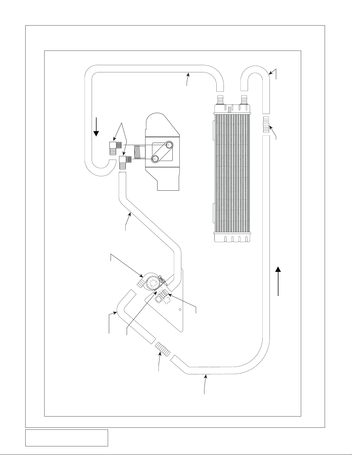
FLOW
Fig. 15-a
Ø90° BRASS FITTINGS
Ø3/4" x 40" HOSE
CHARGE AIR COOLER
180° MOLDED HOSE
Ø3/4"-5/8" HOSE REDUCER
CHARGE COOLER PLUMBING SCHEMATIC (H.O. KITS ONLY)
HOSE
Ø3/4" x 60"
UPSIDE DOWN
WATER PUMP MOUNTED
(BELOW)
90° MOLDED ELBOW
4" x 12" MOLDED HOSE
TOP
HOSEMENDER
SUPPLIED Ø3/4"
(ONE ON TOP OF
TANK, ONE BELOW)
90° BRASS FITTINGS
1/2" NPT x 3/4" HOSE x
Ø3/4" x
70" HOSE
FLOW
Page 31

P/N: 4FJ020-010
©2004 Vortech Engineering, LLC
All Rights Reserved, Intl. Copr.Secured
19APR04 v3.0 Focus(4FJ v3.0)
19
16. BATTERY RELOCATION
Fig. 16-a
Fig. 16-b
Fig. 16-c
Fig. 16-d
NOTE: Clearance between the battery and front
bumper will be tight. Position the battery
box not to interfere with the side marker
lights or front fog lights
NOTE: There might be light contact with the thin
plastic splash guard.
J. Use the supplied batter y ter minal, lug end
and wire to ground the battery to the frame.
K. Reinstall the front bumper cover.Check for
clearance issues. Readjust if necessar y.
REAR LOCATION OF THE
REMOTE BATTERY TERMINAL
.80" SPACER
NEW BATTERY
GROUND
1/4"-20 x 1" SCREW
POSSIBLE LIGHT
CONTACT HERE
A. Remove the battery strap from the stock bat-
tery suppor t bracket. Install the battery strap
into the supplied battery box using the supplied 1/4" hardware.
B. With the front bumper cover removed, align
the battery box along the driver’s side frame
rail. Mark tentative locations for the box to
mount. Place the bumper back into stock
location and check for clearance issues
between the side marker lights, fog lights,
battery box and the plastic inner fender liner.
Take into account clearance when the batter y
will be installed into the battery box. (See Fig.
16-f.)
C. When a position has been found, drill four
13/32" holes in the marked locations.
D. Mount the batter y box in the driver’s side
fender using the supplied spacers and 3/8"
hardware.The .290" spacers will go between
the two forwardmost holes and the upper rear
hole.The lower rear hole will need a .80"
spacer.(See Fig. 16-a.)
E. Install the batter y into the batter y box. Have
the battery orientated so that the ter minals
will be away from the frame rail. Remove the
stock 6mm screw from the factory batter y
strap.Install into its location the supplied 1/4"20 screw and washer. Secure the battery with
the screw and battery strap.
F. Cut any extra ground wires away from the
engine ground strap.Install a ring ter minal on
the ground strap and ground to a clean, paint
free section on the frame.
G. Using a hole saw, make a 1.25" hole inside
the driver’s side fender.Check the location
from the engine compartment before drillling.
(See Figs. 16-c, 16-d.)
H. Mount the remote batter y ter minal as shown.
I. Using the supplied wire, shrink sleeve and lug
terminals, extend the positive wires to the
new remote terminal location. Extend a wire
from the remote battery terminal to the positive terminal on the battery.
NOTE: When wiring the battery, see Fig. 16-e.
NOTE: Secure the positive wires with tie wraps
and shrink sleeves to prevent contact
with other objects.
ENGINE COMPARTMENT VIEW
OF REMOTE BATTERY POST
Page 32

P/N: 4FJ020-010
©2004 Vortech Engineering, LLC
All Rights Reserved, Intl. Copr.Secured
19APR04 v3.0 Focus(4FJ v3.0)
20
Fig. 16-e
16. BATTERY RELOCATION, cont’d.
KEEP THE BATTERY BOX LEVEL
AS THE FRAME RAIL RISES. THIS
WILL MAKE A GAP BETWEEN THIS
CORNER OF THE BATTERY BOX AND
TOP OF THE FRAME RAIL
THERE SHOULD BE LIGHT CONTACT
BETWEEN THIS CORNER AND THE
INSIDE OF THE SPLASH GUARD.
(THE BOX IS PLACED THIS FAR BACK
IN ORDER TO LEAVE CLEARANCE
BETWEEN THE FOG LIGHTS MARKER
LIGHTS AND THE BATTERY)
THIS LOCATION WILL
MOUNT AT THE VERY
BOTTOM OF THE
FRAME RAIL
FRONT OF CAR
MEASURE FROM
BACK SIDE OF
FRONT BUMPER
MOUNT TOP OF
BATTERY BOX
FLUSH WITH TOP
OF FRAME RAIL
3.60"
Fig. 16-f
CUT ENGINE
GROUND FROM
TERMINAL. INSTALL
SUPPLIED RING
TERMINAL AND
GROUND TO
BODY
GROUND TO
FRAME RAIL
WITH VORTECH
SUPPLIED WIRE,
LUG TERMINALS
AND BATTERY
TERMINAL
TO ENGINE BLOCK
DISCARD THE
FACTORY
BATTERY
TERMINAL AND
GROUND WIRE
TO BODY
TERMINAL MODIFIED
-
USE THE SUPPLIED HARDWARE,
RING TERMINALS, SHRINK SLEEVE
AND WIRE TO LENGTHEN THE
POSITIVE LEAD TO THE REMOTE
BATTERY TERMINAL
FACTORY POSITIVE
BATTERY
RUN LEAD TO THE POSITIVE
BATTERY TERMINAL ON
THE RELOCATED BATTERY
5/16" -18
.75" HXHD
+
Page 33

P/N: 4FJ020-010
©2004 Vortech Engineering, LLC
All Rights Reserved, Intl. Copr.Secured
19APR04 v3.0 Focus(4FJ v3.0)
21
Fig. 17-a
17. REFLASH COMPUTER, SVT Models Only
A. Reconnect the batter y.
B. Locate the vehicles OBD2 connector located
in the lower left hand corner of the dash on
the drivers side of the vehicle.(See Fig 17-a.)
C. Attach the OBD2 connector from the Flash
tool that is provided in the kit to the vehicle’s
OBD2 port. (See Fig 17-b.) Make sure this
connector is seated all the way in the vehicles
OBD2 port.You do not want this connector
coming out during programming or damage
may occur to the vehicle’s ECM.
D. The Reflash tool should power up and display
three parameters.
1. Perf ormance Tune
2. Diagnostics
3. Options
E. Select “Performance Tune” and press the
enter button in the middle of the arrow keys.
(See Fig 17-c.)
F. Read the disclaimer entirely, then select
agree and press ENTER.
G. At this point please read the screen displayed
on the reflash tool. If you have any questions,
either refer to the manual that is provided
with the reflash tool or contact our service
department for further assistance.
H. Turn the ignition on (do not start the vehicle).
Set the parking brake and press the ENTER
button to continue.
I. SELECT TUNE will be displayed at the top of
the screen. Use the arrow keys to select the
appropriate tune for your vehicle and press
the ENTER button.You will have a choice of
three to choose from:
1. SVT STD
2. SVT HO
3. Original Backup
J. Continue to follow the screen and when fin-
ished unplug the reflash tool from the vehicles OBD2 port.
IMPORTANT! To ensure trouble-free programming of your vehicle's computer:
• Make sure the vehicle's battery is sufficiently charged.
• Turn off all accessories and close doors to prevent unnecessary drain on the battery.
• Do not attempt to program your vehicle while a battery charger is connected.
• Improper battery voltage will result in failure of the programming process.
• Do not disconnect the cable or turn off the ignition during programming.
NOTE: Do not disturb the cable, or turn the
ignition off during this time. If the programming is disrupted, the computer
will not start or run your vehicle!
Fig. 17-b
Fig. 17-c
ESCAPE
ENTER
OR
SELECT
ARROW
KEYS
Page 34

P/N: 4FJ020-010
©2004 Vortech Engineering, LLC
All Rights Reserved, Intl. Copr.Secured
19APR04 v3.0 Focus(4FJ v3.0)
22
18. FINAL CHECK
A. ZX3 MODELS ONLY - Once the ECM is
received back from Vortech with the
ECM module installed, reinstall the ECM
into the vehicle.In some cases, the
extra height of the ECM module will not
allow the use of the factory hold-down
bracket.Reconnect the factory harness
and reinstall the factory kick panel.
B. Make sure that the oil drain to oil pan fit-
ting is secure and that the engine is
filled with factory specified oil.
C. Fill the factory radiator and the factory
coolant surge tank with a 50/50
coolant/water mix.
D. If your vehicle has gone over 20,000
miles since its last spark plug change,
you will need to change the spark plugs
now before test-driving the vehicle.
E. Check all fittings, nuts, bolts and clamps
for tightness.Pay particular attention to
oil and fuel lines around moving parts,
sharp edges and exhaust system parts.
Make sure all wires and line are properly
secured with clamps or tie-wraps. Make
a visual inspection of the engine and
engine compartment
F. Check all fluid levels, making sure that
your tank is filled with 91 octane or higher fuel before commencing test-drive.
G. (H.O. Kits Only.) With the key on, make
sure the water pump is operating and
that water is flowing through the charge
cooler.Fill as necessar y. If water is not
flowing, remove the supply hose
(attached to the water cooler) and lower
until water flows out of the hose.This
should prime the pump. Reconnect the
hose and verify water flow. Do not run
the water pump for extended periods (30
seconds or more) without water flow.
H. At this point, it is ok to start the vehicle.
I. With the engine running, check power
steering hose connections for leakage.
Let the engine run for two minutes.Turn
the steering wheel in both directions.
Verify:
• Smooth power assist
• Noiseless operation
• Proper fluid level
• No system leaks
• No bubbles, foam or discoleration in
fluid.
WARNING: Do not attempt to operate the
vehicle until all components are
installed and all operations are
completed including the final
check.
J. Recheck to be sure that no hoses,
wires, etc. are near exhaust headers or
moving parts and for signs of any fluid
leakage.
K. Test-drive the vehicle.
L. Recheck the coolant and aftercooler
fluid levels.
M. Read the STREET SUPERCHARGER
SYSTEM OWNER’S MANUAL AND
RETURN THE WARRANTY REGISTRATION FORM within thirty (30) days of
purchasing your supercharger system to
qualify for the 3 year limited warranty.
Page 35

P/N: 4FJ020-010
©2004 Vortech Engineering, LLC
All Rights Reserved, Intl. Copr.Secured
19APR04 v3.0 Focus(4FJ v3.0)
23
This Page Left Intentionally Blank
Page 36

P/N: 4FJ020-010
©2004 Vortech Engineering, LLC
All Rights Reserved, Intl. Copr.Secured
19APR04 v3.0 Focus(4FJ v3.0)
24
1650 PACIFIC AVENUE • CHANNEL ISLANDS, CA 93033-9901 • (805) 247-0226
FAX (805) 247-0669 • www.vortechsuperchargers.com • M-F 8:00 AM - 4:30 PM PST
ENGINEERING, LLC
®
 Loading...