

Page 1
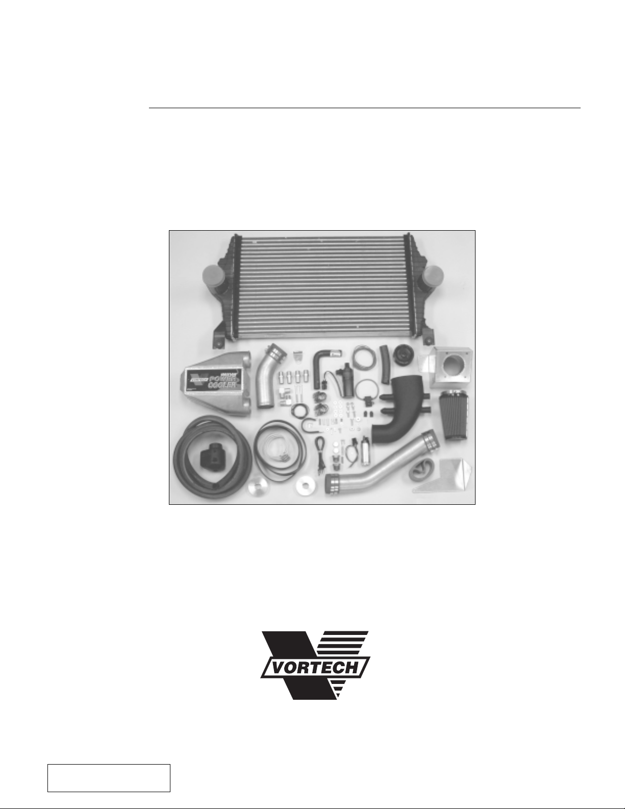
Maxflow® Power Cooler
Installation Instructions
1650 PACIFIC AVENUE • CHANNEL ISLANDS, CA 93033-9901 • (805) 247-0226
FAX (805) 247-0669 • www.vortechsuperchargers.com • M-F 8:00 AM - 4:30 PM PST
P/N: 8N020-100
©2002 Vortech Engineering, LLC
All Rights Reserved, Intl. Copr. Secured
28MAR02 V1.0
(99-01SDPwrCoolr(8N020-100V1.0)
1999-2001 Ford 6.8L Super Duty
Part #8N301-130/138 CARB E.O. #D-213-15
®
ENGINEERING, LLC
Page 2

FOREWORD
Proper installation of this supercharger kit requires general automotive
mechanic knowledge and experience. Please browse through each step of
prior
this instruction manual
should refer the job to a professional installer/technician. Please call Vortech
Engineering for installers in your area.
to beginning the installation to determine if you
All rights reserved. No parts of this publication may be reproduced, transmitted, transcribed,
or translated into another language in any form, by any means without written permission
P/N: 8N020-100
©2002 Vortech Engineering, LLC
All Rights Reserved, Intl. Copr. Secured
28MAR02 V1.0
(99-01SDPwrCoolr(8N020-100V1.0)
© 2002 VORTECH ENGINEERING, LLC
of Vortech Engineering, LLC.
ii
Page 3

Table Of Contents
FOREWORD .....................................................................................................................................ii
TABLE OF CONTENTS ....................................................................................................................iii
TOOL & SUPPLY REQUIREMENTS ................................................................................................ iv
PARTS LIST-1999-2001 FORD SUPER DUTY 6.8L-CHARGE COOLER UPGRADE SYSTEM .....v
1. PREPARATION/REMOVAL ..................................................................................................1
2. SUPERCHARGER RECLOCKING ......................................................................................2
3. IN-TANK FUEL PUMP REPLACEMENT..............................................................................3
4. WATER PUMP AND COOLER INSTALLATION...................................................................4
5. AIR INLET ASSEMBLY ........................................................................................................5
6. CHARGE COOLER INSTALLATION.................................................................................... 6
7. HOSE INSTALLATION & FILLING .......................................................................................7
8. REASSEMBLY AND FINAL CHECK ....................................................................................9
APPENDIX ........................................................................................................................................11
A-1 CHARGE COOLER DIAGRAM ..................................................................................12
A-2 WATER HOSE DIAGRAM ..........................................................................................13
©2002 Vortech Engineering, LLC
iii
All Rights Reserved, Intl. Copr. Secured
28MAR02 V1.0
(99-01SDPwrCoolr(8N020-100V1.0)
P/N: 8N020-100
Page 4

Vortech Maxflow® Power Cooler Installation Instructions
1999-2001 Super Duty V-10
Congratulations on selecting the best performing and most efficient
charge cooler... the VORTECH
®
Maxflow® Power Cooler!
Before beginning this installation, please
read through this entire instruction booklet.
This Vortech Maxflow Power Cooler (referred to in general terms as charge cooler) system was
designed as a street/strip oriented charge cooler, specifically for use on 1999 - 2001 Ford V-10
vehicles equipped with a Vortech supercharger producing up to approximately 580 horsepower.
The Maxflow Power Cooler System will fit and work equally well with other brands of centrifugal
superchargers as well as turbochargers, with minor modifications.
As with any power enhancing product, this system is intended for use on healthy, well-maintained engines. Vortech Engineering is not responsible for engine damage. Installation on new
vehicles will not harm or adversely affect the break-in period so long as factory break-in procedures are followed.
For best performance and continued durability, please take a note of the following key points:
1. Use only premium grade fuel 91 octane or higher (R+M/2).
2. Always listen for any sign of detonation (pinging) and discontinue hard use (no
boost) until problem is resolved.
TOOL & SUPPLY REQUIREMENTS:
• Metric and standard - socket set, wrench set
• Ratchet - 1/2” drive
• Extension
• 1/2" drive breaker bar
• Ford spring lock tool 3/8" & 1/2”
• Pliers
• Drill motor
• Ø1/16" and #30, Ø9/32”, and Ø11/16” drill bits
• Test light
• Rubber mallet or dead blow hammer
• Wire cutters and crimping tool
• Standard hex key set (Allen wrenches)
• Alcohol (denatured or rubbing)
• Silicone sealer/RTV
If your vehicle has in excess of 30,000 miles since its last spark plug change, then you will also need:
• Spark Plug Socket
• NEW Spark Plugs
P/N: 8N020-100
©2002 Vortech Engineering, LLC
All Rights Reserved, Intl. Copr. Secured
28MAR02 V1.0
(99-01SDPwrCoolr(8N020-100V1.0)
iv
Page 5
1999-2001 Ford Super Duty 6.8L
Charge Cooler Upgrade System
®
Part No. 8N301-130/138SQ
ENGINEERING, LLC
PARTS LIST
IMPORTANT: Before beginning installation, verify that all parts are included in the kit. Report any shortages or damaged parts immediately.
Part Number Description Qty Part Number Description Qty
8N101-110 WELDED CORE ASSY. V-10 S.D. 1
4FT112-040 DISCH ASSY PWR COOLR V-10 SD 1
4FT010-060 BRKT, COOLER SUPPORT V-10 S.D. 1
4FT012-040 DUCT, V-10 A.C. TUBE A 1
4FT012-050 DUCT, V-10 A.C. TUBE B 1
4FT012-060 DUCT, V-10 A.C. TUBE C 1
4FT017-080 SPACER, COOLER SUPRT BRKT 1
7C060-025 M6 X 1.0 x 25MM HHCS 1
7F008-020 NUT, M8 x 1.5 1
7J006-094 6MM WASHER S.S. 1
7L312-000 WASHER LOCK 5/16" 1
7R002-044 #44 HOSE CLAMPS 6
7S275-200 2 3/4" x 2" SLEEVE 3
7U034-016 Ø 1.00" G.S. HOSE 6"
8N106-100 WATER COOLER ASSY. V-10 S.D. 1
4FT006-001 WATER COOLER, SUPERDUTY 1
5W018-020 18GA STRD WIRE BLK 3'
7A250-050 1/4-20 x .50" SHCS 2
7A250-075 1/4-20 x 3/4 SHCS PLTD 1
7A250-100 1/4-20 x 1" SHCS 1
7A250-275 1/4-20 x 2.75" SOC HD, ZINC 2
7F250-021 1/4-20 NYLOCK NUT ZINC PLTD. 2
7F250-040 1/4-20 NUT PLATE 2
7J250-001 1/4 SAE WASHER, PLTD 6
7J250-022 1/4" WASHER 2
7P250-020 1/4NPT DRAIN COCK 1
7P500-026 1/2NPT-3/4 BARB 90^ 2
7P500-078 1/2NPT x 3/4 HOSE FIT 4
7R002-052 HOSE CLAMP #52 4
7R007-001 NYLON CLAMP 1-1/8" 8
7S325-200 3.25" x 2.00" SLEEVE 2
7U038-000 3/4" HEATER HOSE 13'
7U100-066 TIE WRAP 11" NYLON 10
8N010-090 MNTG TAB, PLASTIC SURGE TANK 1
8N017-020 ADAPTER, WATER COOLER S.D. 2
8N055-050 CAP, SURGE TANK PLASTIC 1
8N056-060 SURGE TANK
8N107-020 WATER PUMP ASSY. 4.6 1
5W001-011 16-14 GA EYELET 1
5W001-012 SOLDERLESS CONNECTOR 1
5W018-010 18GA STRD WIRE RED 8.25'
5W001-019 SOLDERLESS CONNECTOR 2
5W001-014 FUSE HOLDER 10 GA 1
5W001-015 FUSE, BLADE TYPE 20A 1
5W001-040 12-10GA FEMALE SLIDE 1
5W001-002 FUSE TAP 1
7R003-027 ADEL CLAMP 1-11/16" 1
8F001-402 PUMP, WATER 1
7E010-075 #12 x 3/4" SHEET METAL SCREW 1
7J010-001 #10 FLAT WASHER 1
7U133-060 3/4" x 90° HOSE ELBOW 1
5W001-024 MINI ATC FUSE TAP 1
5W001-025 FEMALE SLIDE, INSULATED, MINI 1
4FT120-020 ECM CHIP PKG ASSY 1
4FT110-030 BRKT ASSY, MAF S.D. GEN II 1
008721 FINISHING PLUGS STEEL 2
2A048-730 BELT 1
2A038-312 8 RIB Ø 3.125 PULLEY 1
8H040-050 AIR FILTER 1
8F101-260 FUEL PMP ASSY, 98+ 4.6,INTANK 1
8F001-260 FUEL PUMP 1
5W001-052 PIGTAIL CONNECTER, FUEL PUMP 1
2A017-048 SPACER, Ø .312 OD / Ø .14 ID 2
5W001-013 14-16AWG, SOLDERLESS CONCTRS 2
7E006-075 #6 x .75 HXHD SHTMTL SCREW 2
4FT011-032 CROWS FOOT, WATER PUMP 1
©2002 Vortech Engineering, LLC
v
All Rights Reserved, Intl. Copr. Secured
28MAR02 V1.0
(99-01SDPwrCoolr(8N020-100V1.0)
P/N: 8N020-100
Page 6

P/N: 8N020-100
©2002 Vortech Engineering, LLC
All Rights Reserved, Intl. Copr. Secured
28MAR02 V1.0
(99-01SDPwrCoolr(8N020-100V1.0)
xii
Page 7

1. PREPARATION / REMOVAL
A. Remove the supercharger drive belt.
B. Remove the entire air inlet assembly. (MAF
bracket, flex hose and aluminum inlet tube.)
C. Disconnect the flex hose from the MAF (Mass
Air Flow meter) and remove the MAF bracket
from the vehicle with the attached meter.
D. NOTE: If your standard supercharger system
has a Gen. I MAF bracket you will need to
remove the MAF meter from the MAF bracket.
(See
Fig. 1-a
.) It will be installed on the supplied
Gen. II MAF bracket in step 5, air inlet assembly.
E. Remove the aluminum discharge duct.
F. Disconnect the oil feed and oil drain lines from
the supercharger. Cap to prevent debris from
entering the open lines.
G. Remove the supercharger from the mounting
plates.
H. If your vehicle has gone over 30,000 miles since
its last spark plug change you will need to
change the spark plugs.
GEN I MAF
BRACKET
ASSEMBLY
GEN II MAF
BRACKET
ASSEMBLY
Fig. 1-a
©2002 Vortech Engineering, LLC
1
All Rights Reserved, Intl. Copr. Secured
28MAR02 V1.0
(99-01SDPwrCoolr(8N020-100V1.0)
P/N: 8N020-100
Page 8

2. SUPERCHARGER RECLOCKING
A. Loosen and remove the six 1/4-20 cap screws
and retaining plates that hold the compressor
housing to the gearcase.
B. Carefully rotate the compressor housing to the
specified location as shown. (See
Figure 2-a
.)
NOTE: If the compressor housing does not
rotate freely relative to the gearcase,
DO NOT FORCE IT. SERIOUS SUPERCHARGER DAMAGE MAY OCCUR. The machined mating surfaces
are designed to prevent pressurized
air from escaping and have minimal
tolerances. If the housing will not move
or is very tight, contact Vortech Engineering immediately at (805) 247-0226
and ask for our service department for
further assistance.
C. Evenly retighten the four cap screws, torque to
60 in/lbs (5ft/lbs).
D. Remove original Ø3.47” supercharger pulley
from the supercharger and install the supplied
Ø3.125” pulley.
NOTE: Included in this kit is a smaller than
originally supplied supercharger pulley. This new pulley is recommended
to achieve best performance results.
Removal of the factory sealed pulley
will reduce the supercharger warranty
from three years to one year unless
the supercharger unit (with the original pulley still attached) and new pulley are sent into Vortech for removal,
installation and re-sealing. If supercharger warranty is not a concern or if
the supercharger warranty has expired, the pulley may simply be removed and replaced with the new part
supplied. Be aware that hammering/
prying etc. on the supercharger may
damage precision parts.
Fig. 2-a
P/N: 8N020-100
©2002 Vortech Engineering, LLC
All Rights Reserved, Intl. Copr. Secured
28MAR02 V1.0
(99-01SDPwrCoolr(8N020-100V1.0)
2
Page 9

3. IN-TANK FUEL PUMP REPLACEMENT
NOTE: The following steps are best per-
A. Support the gas tank with a jack and remove the
screws securing the two gas tank straps.
B. Slightly lower the gas tank and disconnect the
top two vents on the gas tank, front and rear.
C. Disconnect the fuel pump/sender wiring har-
ness located in the frame rail and the fuel fill and
overflow lines.
D. Disconnect the fuel feed and return lines using
a springlock tool.
E. Completely lower the gas tank to the ground.
F. Unscrew the outer ring securing the fuel lines
and remove the cover.
G. Depress the two clips securing the plastic fuel
pump enclosure and slide it out of the tank, the
fuel sender float is attached to the fuel pump
enclosure and must be handled with care. Be
careful not to damage the filter.
H. Cut the two fuel pump power wires about 1” from
the fuel pump electrical connector. Noting the
corresponding (+) and (-) connections, splice
the supplied wiring harness into place using two
solderless connectors.
I. Remove the three screws securing the fuel
pump enclosure’s cover using a 3/16” nut driver
and remove the cover. Cut three equally spaced
1/2" long slits in the perimeter of the cover’s fuel
pump locating cylinder (see
lows the larger O.D. pump to fit in the cover.
Some material may need to be removed from
the I.D. of the pump locating cylinder for proper
pump fit.
J. Remove the stock fuel pump from its enclosure.
Separate the rubber pump support and filter
from the pump and install both onto the supplied
pump.
K. Reassemble the new fuel pump assembly and
canister with cap. Install the supplied 1/8” spacers beneath the pump outlet manifold and the
canister cap. (See
manifold mount holes as a template, drill two 1/
16” pilot holes into the enclosure cover. Secure
the outlet manifold to the cap using the two self
tapping #6 screws. Reinstall the fuel tank assembly and reattach the electrical connections.
L. Reinstall the canister assembly into the fuel tank
and screw on the outer ring to secure it.
M. Reinstall the gas tank and reconnect all the fuel
lines and electrical connections.
formed with the gas tank with the
least amount of fuel in it as possible.
Fig. 3-b
Fig. 3-a
.) Using the outlet
). This al-
PLASTIC FUEL
PUMP OUTLET
MANIFOLD
BYPASS
TUBE
CUT THREE 1/2"
LONG SLITS HERE
Fig. 3-a
#6 SCREWS
FUEL OUTLET
SUPPLIED 1/8"
SPACERS
PUMP CANISTER
Fig. 3-b
HOSE
FUEL PUMP OUTLET
©2002 Vortech Engineering, LLC
3
All Rights Reserved, Intl. Copr. Secured
28MAR02 V1.0
(99-01SDPwrCoolr(8N020-100V1.0)
P/N: 8N020-100
Page 10

4. WATER PUMP AND COOLER INSTALLATION
A. Remove the upper shroud, located between the
core support and the grille.
B. Remove the three screws securing the radiator
reservoir and rotate out of the way.
C. Remove jack tools and tray holding brackets.
D. Remove the upper two supports securing the
condenser.
E. Remove the hood latch from the core support
(leaving it attached to the cable) and set out of
the way.
F. Remove the upper core support - secured with
(8-10) screws. (See
G. Following the
Fig. 4-a
Fig 7-b
supplied water fitting adapters onto the heat
exchanger securing with the provided Ø3.25” x
2” sleeves and clamps.
H. Using the diagram as a guide, install the sup-
plied 3/4” NPT brass fittings into the charge
cooler as shown. A small amount of thread
sealant may be used on these threads.
I. Lower the heat exchanger into place between
the vehicle’s condenser and radiator. Rest the
heat exchanger on the pads of the lower core
support. (See
Fig. 4-b
J. Remove the factory nut clips if any, in the core
support and replace with the ones provided.
Secure the heat exchanger to the vehicle using
the supplied 1/4-20 x 2-3/4” cap screws and
washers.
K. Reinstall the upper core support, hood latch and
condenser supports.
L. Using the
Fig. 4-c
as a guide, measure down 20”
from the top of the fan shroud and over 5” and
drill a hole through the fan shroud using a Ø9/
32” drill bit.
M. Using the supplied adel clamp and 1/4” screw,
washers and nylock nut secure the pump to the
fan shroud.
N. Cut the stock connector off of the pump wiring
and install the provided solderless connectors.
Connect the supplied red wire to the green wire
and the supplied black wire to the brown wire
using the previously installed connectors.
O. Reinstall the vehicle’s stock fan, spacer, shroud
and tighten.
P. Connect the black wire to a suitable ground, free
from paint and vehicle undercoating.
Q. Route the red wire to the vehicle’s fuse box
located near the master cylinder. Using the
supplied fuse tap, fuse holder and slide connectors, tap into the #7 mini-fuse. Check that the
fuse only receives power when the key is in the
ON position using a test light.
.)
on page 8, install the
.)
Fig. 4-a
Fig. 4-b
Fig. 4-c
P/N: 8N020-100
©2002 Vortech Engineering, LLC
All Rights Reserved, Intl. Copr. Secured
28MAR02 V1.0
(99-01SDPwrCoolr(8N020-100V1.0)
4
Page 11

5. AIR INLET ASSEMBLY
A. Attach the MAF meter to the MAF bracket using
the supplied 1/4” hardware. Slide the air filter
onto the tube of the MAF bracket. Using a 5/16”
nut driver or socket, reach in through one of the
Ø5/8” holes and tighten the hose clamp. Cover
the holes with the provided finishing plugs.
B. Install the MAF assembly onto the driver’s side
of the core support using the factory hardware.
(See
Fig. 5-a
.)
?
NOTE: The thick rubber mat may need to be
unsnapped and folded over toward the
radiator to allow proper mounting of
the MAF assembly.
C. Reconnect the MAF wiring connector to the
MAF meter.
D. Reinstall the supercharger and connect the oil
feed and drain lines.
E. Reinstall the Ø3.5” x 2” silicone sleeve and #56
hose clamps onto the supercharger inlet. Install
the cast aluminum inlet duct into the silicone
sleeve and tighten the hose clamps.
F. Connect the cast aluminum duct to the MAF
meter using the supplied Ø3.5" x 15" flex hose
and secure with #52 hose clamps.
G. Install the short end of the Ø5/8" molded elbow
hose onto the Ø5/8" bung on the air inlet.
NOTE: Refer to Fig. A1 in the Appendix.
H. Cut a 90° section from the stock crank case
breather hose and attach to the Ø5/8" molded
elbow hose with the Ø5/8" union. Reconnect the
other end to the crank case breather on the
valve cover. Trim hose length for a proper fit.
Fig. 5-a
©2002 Vortech Engineering, LLC
5
All Rights Reserved, Intl. Copr. Secured
28MAR02 V1.0
(99-01SDPwrCoolr(8N020-100V1.0)
P/N: 8N020-100
Page 12

6. CHARGE COOLER INSTALLATION
A. Remove the coolant line attached to the intake
manifold (see
2” from the bottom of the coolant line (to allow for
clearance of the cooler support bracket) and
reinstall.
B. Cut 4-1/2” off of the supplied piece of foam tape
and the remaining 7-1/2” in half. Thoroughly
clean the top portion of the cooler support bracket
with alcohol and allow it to dry. Following the
diagram (see
the top of the cooler support bracket. Trim the
excess from any over hanging edge.
C. Following the photo (see
supplied cooler support bracket onto the front
passenger’s side of the intake manifold and
secure it using the provided spacer and 6mm
hardware.
NOTE: The spacer is located between the
Secure the lower part of the bracket to the front
cover’s 8mm stud using the 8mm nut and lock
washer provided.
D. Install the provided Ø2-3/4” x 2” sleeves onto
each one of the cooler ducts along with four #44
hose clamps (2 per sleeve).
E. Install the plastic discharge duct onto the throttle
body and secure with the supplied Ø4-1/2”
sleeve and two #72 hose clamps. (See
F. Connect the idle air line and the bypass valve to
the duct as shown (see
using the #16 hose clamps.
G. Connect the bypass valve to the cast air inlet
duct using the supplied Ø1” x 6” hose and
secure using two #16 hose clamps.
H. Slide the Ø3” x Ø2-3/4” reducer sleeve onto the
plastic discharge duct and secure with one #48
hose clamp.
I. Slide one Ø2-3/4" x 2" sleeve and two #44 hose
clamps onto the discharge of the supercharger.
J. Following
the supercharger and discharge duct “B” to the
previously installed plastic duct leading to the
throttle body.
K. Set the charge cooler on top of the cooler
support bracket and connect the discharge ducts
to the charge cooler securing it with the previously installed hose clamps.
Fig. 6-a
Fig. 6-b
cooler support bracket and the top of
the manifold.
Fig. 6-d
). Remove approximately
) attach the foam tape to
Fig. 6-c
Fig. 6-d
) install the
) and secure
, attach discharge duct “A” to
Fig. 6-d
Fig. 6-a
.)
Fig. 6-b
NOTE: Discharge duct “A” must be rotated
P/N: 8N020-100
©2002 Vortech Engineering, LLC
All Rights Reserved, Intl. Copr. Secured
28MAR02 V1.0
(99-01SDPwrCoolr(8N020-100V1.0)
over enough so that the vehicle’s hood
does not come in contact with the duct.
Fig. 6-c
6
Page 13

6. CHARGE COOLER INSTALLATION , cont’d.
DUCT, TUBE C
DUCT, TUBE A
CHARGE AIR
COOLER
CONNECT TO VALVE COVER
TO IDLE AIR CONTROL
DUCT, TUBE B
MAF BRACKET ASSEMBLY
Ø5/8" HOSE
UNION
ALUMINUM
INLET
DUCT
BYPASS
VALVE
FLEX HOSE
Fig. 6-d / See Appendix A-1 for detail
7. HOSE INSTALLATION & SYSTEM FILLING
A. Attach the surge tank mounting bracket to the
surge tank using the supplied 1/4" hardware.
Using
a template. Drill a Ø9/32" hole in the vehicle’s
evaporator bracket and secure the surge tank
assembly with the 1/4" hardware.
B. Cut an 8" section of the Ø3/4" hose and attach
one end to the driver’s side fitting on the water
cooler and the other end to the inlet of the water
pump. Secure both ends with the provided nylon
clamps. (See
Fig. 7-a
and the surge tank assembly as
Fig. 7-b
.)
Fig. 7-a
©2002 Vortech Engineering, LLC
7
All Rights Reserved, Intl. Copr. Secured
28MAR02 V1.0
(99-01SDPwrCoolr(8N020-100V1.0)
P/N: 8N020-100
Page 14

7. HOSE INSTALLATION & SYSTEM FILLING, cont’d.
C. Cut a 98" section of the Ø3/4" hose and attach
one end to the discharge of the water pump and
secure with a nylon clamp. Route the hose
toward the firewall and the back of the engine.
Connect the hose to the straight fitting on the
charge cooler and secure with a nylon clamp.
Make sure the hose is away from sharp edges
and exhaust system. Ensure that
sharp bends are allowed on any of the hoses.
D. Cut a 23" section of the Ø3/4" hose and connect
between the bottom of the surge tank and the
water cooler. Secure both ends with nylon
clamps.
E. Temporarily plug the hose fitting on the surge
tank that is to connect to the 90° fitting on the
charge cooler.
F. When filling the system, ensure that the
IS OFF
and the drain valve on the water cooler
is OPEN.
G. Pour 3/4 of a gallon of antifreeze into the surge
tank. Fill the system with water until water comes
out of the drain fitting, then close the drain valve
but
do not over tighten
.
H. Continue to fill the system with water until it
pours out of the OPEN fitting on the charge
cooler.
I. Connect the water line from the surge tank to the
charge cooler and secure with the provided
clamps. Top the system off with water and install
the surge tank cap.
NO
kinks or
PUMP
98
"
SURGE TANK TOP VIEW
23"
CONNECTS
TO
BOTTOM
OF
SURGE
TANK
SURGE TANK
SIDE VIEW
8"
CHARGE AIR
COOLER
3/4" NPT
BRASS
FITTING
ADAPTER
Ø3.25" X 2"
AIR FROM
SUPERCHARGER
AIR TO
THROTTLE
BODY
WATER PUMP
WATER COOLER
FRONT OF VEHICLE
Fig. 7-b / See Appendix A-2 for detail
DENOTES
FLOW
DIRECTION
8"
P/N: 8N020-100
©2002 Vortech Engineering, LLC
All Rights Reserved, Intl. Copr. Secured
28MAR02 V1.0
(99-01SDPwrCoolr(8N020-100V1.0)
8
Page 15

8. REASSEMBLY AND FINAL CHECK
NOTE: Once the ECM is received back from
Vortech with the ECM module installed,
reinstall the ECM into the vehicle. In some
cases, the extra length of the ECM module will not allow the use of the factory holddown bracket unless it is modified. Reconnect the factory harness.
A. Reinstall the stock surge tank and tire iron.
Reinstall the upper radiator hose opposite of the
factory installation (the short leg of the hose
should connect to the radiator). (See
Fig. 8-a
Refill the radiator.
B. Reconnect the battery.
C. Check all fittings, nuts, bolts and clamps for
tightness. Pay particular attention to oil and fuel
lines, especially around moving parts, sharp
edges and exhaust. Make sure all wires and
lines are properly secured with clamps or tie
wraps.
D. Check all fluid levels, making sure that your fuel
tank is filled with 91 octane or higher fuel before
commencing test drive.
E. Start engine and allow to idle a few minutes,
then shut off.
F. Recheck to be sure that no hoses, wires, etc. are
near exhaust headers or moving parts and for
signs of fluid leakage.
.)
Fig. 8-a
WARNING: Operating the vehicle without ALL
the subassemblies completely and
properly installed may cause F AILURE OF MAJOR COMPONENTS.
G. Test drive the vehicle. Listen for any sign of
detonation (pinging) and discontinue hard use
(no boost) until problem is resolved.
Fig. 8-b
©2002 Vortech Engineering, LLC
9
All Rights Reserved, Intl. Copr. Secured
28MAR02 V1.0
(99-01SDPwrCoolr(8N020-100V1.0)
P/N: 8N020-100
Page 16

P/N: 8N020-100
©2002 Vortech Engineering, LLC
All Rights Reserved, Intl. Copr. Secured
28MAR02 V1.0
(99-01SDPwrCoolr(8N020-100V1.0)
10
Page 17

APPENDIX
11
©2002 Vortech Engineering, LLC
All Rights Reserved, Intl. Copr. Secured
28MAR02 V1.0
(99-01SDPwrCoolr(8N020-100V1.0)
P/N: 8N020-100
Page 18

APPENDIX A-1
V-10 Inlet And Discharge Diagram
DUCT, TUBE A
CONNECT TO VALVE COVER
DUCT, TUBE C
Ø5/8" HOSE UNION
TO IDLE AIR CONTROL
ALUMINUM
INLET
DUCT
BYPASS
VALVE
CHARGE AIR
COOLER
P/N: 8N020-100
©2002 Vortech Engineering, LLC
All Rights Reserved, Intl. Copr. Secured
28MAR02 V1.0
(99-01SDPwrCoolr(8N020-100V1.0)
DUCT, TUBE B
MAF BRACKET ASSEMBLY
FLEX HOSE
12
Page 19

DENOTES FLOW
DIRECTION
WATER PUMP
AIR TO THROTTLE BODY
AIR FROM
SUPERCHARGER
ADAPTER
3/4" NPT BRASS FITTING
23"
SURGE TANK
SIDE VIEW
SURGE TANK
TOP VIEW
8"
CHARGE AIR COOLER
98"
Ø3.25" X 2" SLEEVE
CONNECTS TO
BOTTOM OF
SURGE TANK
WATER COOLER
FRONT OF VEHICLE
8"
APPENDIX A-2
Water Hose Diagram
13
©2002 Vortech Engineering, LLC
All Rights Reserved, Intl. Copr. Secured
28MAR02 V1.0
(99-01SDPwrCoolr(8N020-100V1.0)
P/N: 8N020-100
Page 20

®
ENGINEERING, LLC
1650 PACIFIC AVENUE • CHANNEL ISLANDS, CA 93033-9901 • (805) 247-0226
FAX (805) 247-0669 • www.vortechsuperchargers.com • M-F 8:00 AM - 4:30 PM PST
©2002 Vortech Engineering, LLC
All Rights Reserved, Intl. Copr. Secured
28MAR02 V1.0
(99-01SDPwrCoolr(8N020-100V1.0)
P/N: 8N020-100
 Loading...