

Page 1
PN: 8N020-130 v1.0 — F-150 PwrClr 09/19/05
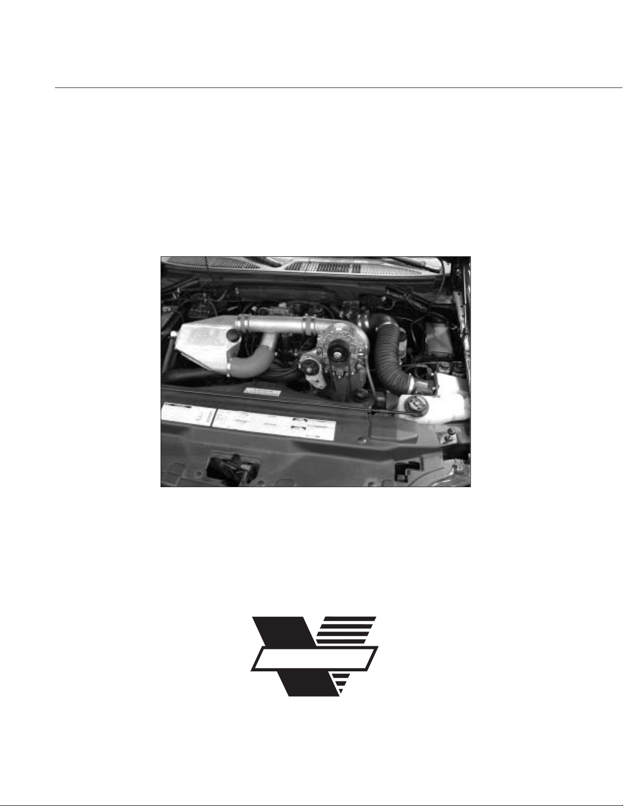
Maxflow®Power Cooler
®
Installation Instructions
1997-2003 Ford 5.4 F-150/Expedition
P/N: 8N301-300/308
ENGINEERING, LLC
1650 PACIFIC AVENUE • CHANNEL ISLANDS, CA 93033-9901 • 805 247-0226
FAX: 805 247-0669 • www.vortechsuperchargers.com • M-F 8:00 AM - 4:30 PM PST
VORTECH
®
Page 2

P/N: 8N020-130
© 2005 Vortech Engineering, LLC
All Rights Reserved, Intl. Copr. Secured.
19SEP05 v1.0 97-03F150PwrClr(8N020-130v1.0)
ii
FOREWORD
Proper installation of this supercharger kit requires
general automotive mechanic knowledge and experience. Please read through each step of this
instruction manual prior to beginning the installation
to determine if you should refer the job to a professional installer/technician. Please call Vortech
Engineering for installers in your area.
© 2005 VOR TECH ENGINEERING, LLC
All rights reserved. No parts of this publication may be reproduced, transmitted, transcribed,
or translated into another language in any form, by any means without written permission
of Vortech Engineering, LLC.
Page 3

P/N: 8N020-130
© 2005 Vortech Engineering, LLC
All Rights Reserved, Intl. Copr. Secured.
19SEP05 v1.0 97-03F150PwrClr(8N020-130v1.0)
iii
TABLE OF CONTENTS
FOREWORD . . . . . . . . . . . . . . . . . . . . . . . . . . . . . . . . . . . . . . . . . . . . . . . . . . .ii
TABLE OF CONTENTS . . . . . . . . . . . . . . . . . . . . . . . . . . . . . . . . . . . . . . . . . .iii
NOTICES . . . . . . . . . . . . . . . . . . . . . . . . . . . . . . . . . . . . . . . . . . . . . . . . . . . . .iv
TOOL & SUPPLY REQUIREMENTS . . . . . . . . . . . . . . . . . . . . . . . . . . . . . . . . .v
PARTS LIST - 1997-2003 5.4L Ford F-150/Expedition . . . . . . . . . . . . . . . . . . . . vi
1. PREPARATION AND REMOVAL . . . . . . . . . . . . . . . . . . . . . . . . . . . . . . .1
2. SUPERCHARGER RECLOCKING . . . . . . . . . . . . . . . . . . . . . . . . . . . . .2
3. DISCHARGE INSTALLATION . . . . . . . . . . . . . . . . . . . . . . . . . . . . . . . . .3
4. WA TER RESERVOIR/PUMP INSTALLATION . . . . . . . . . . . . . . . . . . . . . .4
5. WA TER COOLER INSTALLATION . . . . . . . . . . . . . . . . . . . . . . . . . . . . . .5
6. WA TER PUMP WIRING . . . . . . . . . . . . . . . . . . . . . . . . . . . . . . . . . . . . . .7
7. FUEL MANAGEMENT UNIT RECALIBRATION . . . . . . . . . . . . . . . . . . . .8
8. REASSEMBLY AND FINAL CHECK . . . . . . . . . . . . . . . . . . . . . . . . . . . .9
Page 4

P/N: 8N020-130
© 2005 Vortech Engineering, LLC
All Rights Reserved, Intl. Copr. Secured.
19SEP05 v1.0 97-03F150PwrClr(8N020-130v1.0)
iv
This product may not be legal for use on public roads in all 50 states.
NOTICES
(Read before installation is started)
Included in this kit is a smaller than originally supplied supercharger pulley. This new
pulley is recommended to achieve the best performance results. Removal of the factory sealed pulley will reduce the supercharger warranty from three years to one year
unless the supercharger unit (with the original pulley still attached) and new pulley are
sent into Vor tech for removal, installation and re-sealing. If the supercharger warranty
is not a concern or if the supercharger warranty has expired, the pulley may simply be
removed and replaced with the new part supplied.Hammering/prying etc. on the supercharger and/or pulley will cause damage to the parts. Light heating of the supercharger pulley with a propane torch (if the pulley is tight on the shaft) will aid remov al.A return
authorization number is required before the supercharger and pulley are sent into
Vortech.Call the Vor tech service depar tment at (805) 247-0226 for a return authorization number.Return freight (ground) will be paid by Vor tech.
This product is protected by state common law, copyright and/or patent. All legal
rights therein are reserved.The design, layout, dimensions , geometry, and engineering features shown in this product are the exclusive property of Vortech
Engineering, LLC.This product ma y not be copied or duplicated in whole or part,
abstractly or fundamentally, intentionally or fortuitously, nor shall any design,
dimension, or other information be incorporated into any product or apparatus
without prior written consent of Vortech Engineering, LLC.
Custon ECM calibration by a competent tuner is suggested before operation at
wide open throttle.
Page 5

P/N: 8N020-130
© 2005 Vortech Engineering, LLC
All Rights Reserved, Intl. Copr. Secured.
19SEP05 v1.0 97-03F150PwrClr(8N020-130v1.0)
v
Vortech Maxflow Power Cooler
©
Installation Instructions
1997-2003 5.4L F-150/Expedition
Before beginning this installation,
please read through this entire instruction booklet
The Vor tech Maxflow Power Cooler system was designed as a street/strip oriented aftercooler, specifically for use on 1997-2003 5.4L F-150/Expedition
vehicles equipped with a Vortech supercharger.
As with any power enhancing product, this system is intended for use on
healthy, well-maintained engines. Vortech Engineering is not responsible for
engine damage. Installation on new vehicles will not harm or adversely affect
the break-in period so long as factory break-in procedures are followed.
For best performance and continued durability, please take a note of the following key points:
1. Use only premium grade fuel 91 octane or higher (R+M/2).
2. Always listen for any sign of detonation (pinging) and discontinue hard use (no
boost) until problem is resolved.
TOOL & SUPPLY REQUIREMENTS:
• Metric and standard - socket set, wrench set
• Ratchets - 1/2", 3/8", 1/4" drive
• Extensions: 3" & 6"
• 1/2" drive breaker bar
• Pliers
• Drill motor
• Ø1/16" and #30, Ø9/32", and Ø11/16" drill bits
• Test light
• Wire cutters and crimping tool
• Standard hex key set (Allen wrenches)
• Silicone sealer/RTV
Congratulations on selecting the best performing and most
efficient aftercooler today... the Vortech Maxflow Power Cooler!
If your vehicle has in excess of 30,000 miles since its last spark plug change, then you will also need:
• Spark Plug Socket
• NEW Spark Plugs
Page 6

P/N: 8N020-130
© 2005 Vortech Engineering, LLC
All Rights Reserved, Intl. Copr. Secured.
19SEP05 v1.0 97-03F150PwrClr(8N020-130v1.0)
vi
1997-2003 Ford F-150/Expedition 5.4L
Charge Cooler Upgrade System
Part No. 8N301-300/308
®
ENGINEERING, LLC
PARTS LIST
2A038-295 S/C PULLEY 2.95" 8-GRV 1
4FM212-010 DISCHARGE ASY, '99-'03 5.4 F-150 1
4FM112-015 DISCHARGE TUBE “A”, F-150 H.O. 1
4FM012-016 DISCHARGE TUBE “B”, F-150 H.O. 1
7S275-200 SLEEVE, Ø2.75" x 2.00"L, BLUE 2
7S300-200 SLEEVE, 3" x 2", BLUE 2
7U034-016 1" GS HEATER HOSE .5'
7U034-016 1" GS HEATER HOSE 1.0'
7R002-044 #44 SAE TYPE “F” SS HOSE CLAMP 4
7R002-048 #48 SAE TYPE “F” SS HOSE CLAMP 4
8N055-050 PLASTIC CAP, SURGE TANK 1
7R002-016 #16 SS HOSE CLAMP 4
7U030-046 5/32" VACUUM LINE 2'
7P156-082 5/32" TEE 1
8D001-001 STD COMPRESS BYPASS VALVE 1
8N105-180 WATER TANK/COOLER ASY, '99-'03 1
8N055-030 TANK, WATER TRIANGLE SHAPE 1
7R007-001 NYLON RATCHET CLAMP, 1-1/8" 10
4FM010-180 BRKT, TRIANGLE RES, F-150 H.O. 1
7P500-026 1/2"NPT x 3/4" BARB, 90° BRASS 6
8N006-010 WATER COOLER, SETRAB SINGLE PAS 1
4FM010-190 BRKT, SETRAB UPPER, F-150 H.O. 2
4FM010-170 BRKT, SETRAB LOSER, F-150 H.O. 1
7E010-049 #10 x 3/4" HEX HD SLF DRL SHT MTL 5
7A250-049 1/4-20 x .75" SHCS PLTD 8
7F250-021 1/4-20 NYLOCK NUT, ZINC PLATED 5
7J250-022 1/4" WASHER SAE STAINLESS 15
7U038-000 3/4" HEATER HOSE 15'
7U038-012 HOSE, Ø3/4" x 90°, 4" x 12" LEGS 2
7P375-075 3/4" HOSE BARB UNION, BRASS 1
7J010-001 #10 FLAT WASHER 5
7U100-055 TIE-WRAP, 7.5" NYLON 10
8N107-180 WATER PUMP ASY, 5.4 H.O. 1
5W014-010 14GA STRD WIRE, RED UL1015 8'
5W001-009 16-14GA MAKE SLIDE, INSULATED 2
5W001-010 16-14GA, FEMALE SLIDE, INSULATED 2
5W001-011 16-14GA RING TERM, .26" HOLE 1
5W014-030 14GA STRD WIRE, BLACK 5'
5W001-032 1/4" PLASTIC WIRE LOOM 5"
5W001-041 12-10GA, MALE SLIDE, INSULATED 1
5W001-022 T-TAP CONN, 14-16 AWG 1
5W001-054 16GA FUSE HOLDER WITH WIRE 1
5W001-013 14-16GA BUTT CONN, BLUE, INSULATED 2
5W001-015 FUSE, BLADE TYPE, 20AMP 1
7U100-055 TIE-WRAP, 7.5" NYLON 8
8F001-402 PUMP, WATER, PIERBURG 1
7R003-027 ADEL CLAMP, 1-11/16" 1
8N201-310 WELDED CORE ASY, 5.4 H.O. 1
8N003-030 COOLER DUCT, LT1, GROUND 1
8N030-070 DUCT, COOLER OUTLET, LS1 FBODY 1
8N201-001 WELDED CORE ASSY w/ENDS, S2K 1
8R101-002 PULLEY RETAINER ASSY, 8-RIB 1
2A040-011 PULLEY RETAINER, S/C 1
7B375-125 3/8-24 x 1-1/4" HXHD GR8
7K375-040 3/8"AN960 FLAT WASHER, PLATED 1
7U100-070 KEY, 3/16"SQUARE x 7/8"LONG 1
6Z170-020 8:1 RING SPACER ASSY 1
6Z050-191 FMU WASHER, 8:1 PLATED 1
6Z070-030 FMU 8:1 RING SPACER 1
6Z020-140 LRG DIAPHRAGM, FLOURO 1
007032 FMU RECALIBRATION INSTRUCTIONS 1
6Z170-020 RING AND SPACER, 8:1 FMU 1
2A048-795 8-RIB BELT 1
PART NUMBER DESCRIPTION QTY
Page 7

P/N: 8N020-130
© 2005 Vortech Engineering, LLC
All Rights Reserved, Intl. Copr. Secured.
19SEP05 v1.0 97-03F150PwrClr(8N020-130v1.0)
1
1. Preparation and Removal
A. Disconnect and remove the negative bat-
tery terminal.
B. Remove the supercharger discharge tube
and bypass valve assembly.
C. Remove and set aside the supercharger
inlet elbow and flex tube.
D. Remove the supercharger drive belt and
supercharger.Set aside.
NOTE: Temporarily cap oil feed and oil drain to
protect your engine from foreign particles.
E. Remove the FMU, disconnect the lines not-
ing their position for re-assembly.
Page 8

P/N: 8N020-130
© 2005 Vortech Engineering, LLC
All Rights Reserved, Intl. Copr. Secured.
19SEP05 v1.0 97-03F150PwrClr(8N020-130v1.0)
2
2. Supercharger Reclocking
A. Loosen and remove the six 1/4-20 cap
screws and retaining plates that hold the
compressor housing to the gearcase.
B. Carefully rotate the compressor housing to
the specified location as shown. (See Fig.
2-a.)
C. Evenly retighten the six cap screws, torque
to 60 in/lbs (5ft/lbs).
D. Remove original Ø3.33" supercharger pul-
ley from the supercharger and install the
supplied Ø2.95" pulley. Use heat on the
pulley if necessary.
Fig. 2-a
F-150 5.4L H.O.Supercharger Clocking
NOTE: If the compressor housing does not
rotate freely relative to the gearcase, DO
NOT FORCE IT. SERIOUS SUPERCHARGER DAMAGE MAY OCCUR. The
machined mating surfaces are designed
to prevent pressurized air from escaping
and have minimal tolerances. If the housing will not move or is very tight, contact
Vortech Engineering immediately at
(805) 247-0226 and ask for our service
department for further assistance.
NOTE: Included in this kit is a smaller than orig-
inally supplied supercharger pulley. This
new pulley is recommended to achieve
best performance results. Removal of the
factory sealed pulley will reduce the
supercharger warranty from three years
to one year unless the supercharger unit
(with the original pulley still attached)
and new pulley are sent into Vortech for
removal, installation and re-sealing. If
supercharger warranty is not a concern
or if the supercharger warranty has
expired, the pulley may simply be
removed and replaced with the new part
supplied. Be aware that hammering/prying etc. on the supercharger may damage precision parts.
Page 9

P/N: 8N020-130
© 2005 Vortech Engineering, LLC
All Rights Reserved, Intl. Copr. Secured.
19SEP05 v1.0 97-03F150PwrClr(8N020-130v1.0)
3
3. Discharge Installation
A. Locate the supplied Ø2.75" straight dis-
charge duct. Using a Ø2.75" x 2.0" silicone
sleeve connect the end closest to the
bypass bung to the discharge of the supercharger.Secure this end with #44 hose
clamps. At this time, snug the hose clamps
to leave the ability to fine tune the discharge assembly. (See Fig. 3-a.)
B. Locate the Ø2.75 x 90° discharge tube.
Using a Ø3.0" to 2.75" reducer and silicone
sleeve, connect the lightly curved end to
the throttle body. Point the 90° end of the
duct to the passenger’s side of the vehicle.
C. Install two 3/4" x 90° brass fittings into the
two threaded ports in the supplied charge
cooler.
D. Using the Ø2.75" x 2.0" silicone sleeves
connect the corresponding ends of the
cooler to the open ends of the discharge
ducts. Secure the Ø2.75" end with #44
hose clamps.
E. Align the discharge assembly and tighten
all hose clamps.
F. Lightly bend down the radiator hose sup-
port so that the charge cooler does not rub
against the radiator hose.
Fig. 3-a
Fig. 3-b
Ø2.75" SILICONE SLEEVES
& #44 HOSE CLAMPS
90° BRASS
FITTINGS
Page 10

P/N: 8N020-130
© 2005 Vortech Engineering, LLC
All Rights Reserved, Intl. Copr. Secured.
19SEP05 v1.0 97-03F150PwrClr(8N020-130v1.0)
4
A. Locate the front bumper/fender support
brace from underneath the front passenger’s side fender well. (See Fig. 4-a.)
B. Remove the two screws securing the
brace, then remove the brace.
C. Using an adel clamp mount the supplied
water pump to the triangle water tank. (See
Fig. 4-b.)
D. Dr ill through the two 1/2"NPT ports in the
water reservoir if necessary.Be careful not
to contact the threads. Blow out any debris
from inside the tank. Install a supplied
Ø3/4" x 90° brass fitting in each threaded
hole. Use thread sealant on the threads to
help prevent leakage.
E. Connect the pump inlet to the bottom 90°
brass fitting with the supplied 4" x 12" rubber hose. Fit the hose, then cut it to length.
(See Fig. 4-b.)
F. Mount the pump/tank assembly to the sup-
plied mounting bracket with the supplied
1/4-20 x .50" SHCS. (See Fig. 4-c.)
G. Using the factory hardware mount the
entire pump/tank assembly into the fender
well in place of the factory support. (See
Fig. 4-d.) It may be necessary to bend the
horn out of the way to gain clearance.
4. Water Reservoir/Pump Installation
Fig. 4-a
Fig. 4-b
Fig. 4-c
Fig. 4-d
PASSENGER SIDE SUPPORT BRACE
Page 11

P/N: 8N020-130
© 2005 Vortech Engineering, LLC
All Rights Reserved, Intl. Copr. Secured.
19SEP05 v1.0 97-03F150PwrClr(8N020-130v1.0)
5
5. Water Cooler Installation
A. If not already removed, take off the
plastic cover over the radiator.This will
allow access to the area behind the grill
and in front of the radiator.
B. Locate the supplied Setrab cooler and L-
shaped brackets. Attach the brackets to the
top of the tabs on the Setrab cooler.(See
Fig. 5-a.)
C. Position the cooler behind the grill with the
L-shaped tabs pointing upward. Align the
tabs along the side of the cross-member
and mark locations of the four Ø3/32" pilot
holes to be drilled. (See Fig. 5-b.)
D. Dr ill the holes and temporarily mount the
water cooler.
E. Locate the supplied lower mounting brack-
et. Using the supplied 1/4" hardware secure
one end of the bracket to the forward-most
hole on the lower driver’s side flange of the
cooler.Point the bracket toward the grill.
(See Fig. 5-c.) Mark where the hole sits
over the rear grill support rib. Use a sheet
metal screw to secure the bracket to the
grill.
For the following steps, see Fig. 5-d:
F. Locate the 4" x 12" x 90° molded hose.
Connect the short end of the supplied 90°
hose to the top fitting on the installed water
reservoir.Using a hose mender and supplied length of hose connect the open end
of the 90° hose to the lower fitting on the
charge cooler.Route the hose along side
the passenger’s side of the radiator snaking
down to the upper brass fitting.
G. Using a section of Ø3/4" hose connect the
discharge of the water pump to the passenger’s side 90° fitting in the setrab water
cooler.Route the hose near the frame rail
in front of the radiator and up to the
installed cooler.
H. Using the supplied Ø3/4" hose, connect the
driver’s side fitting in the Setrab cooler to
the upper 90° fitting in the setrab water
cooler.Route the hose to the passenger’s
side of the radiator passing by the core
support, up to the charge cooler.
I. Secure all ends with the supplied nylon
ratchet clamps.
Fig. 5-a
Fig. 5-b
Fig. 5-c
CONNECT TO LOWER
D-SIDE TAB ON
SETRAB COOLER
SECURE TO THE
REAR OF THE
FACTORY GRILL
Page 12

P/N: 8N020-130
© 2005 Vortech Engineering, LLC
All Rights Reserved, Intl. Copr. Secured.
19SEP05 v1.0 97-03F150PwrClr(8N020-130v1.0)
6
Fig. 5-d
4" x 12" x 90° HOSE
TRIMMED TO FIT
1/2"NPT x 3/4" BARB x 90°
1/2"NPT x 3/4" BARB x 90°
WATER RESERVOIR
WATER PUMP
3/4" HOSE MENDER
1/2"NPT x 3/4" BARB x 90°
VORTECH
CHARGE COOLER
WATER
FILL PORT
WATER DIRECTION FLOW
Page 13

P/N: 8N020-130
© 2005 Vortech Engineering, LLC
All Rights Reserved, Intl. Copr. Secured.
19SEP05 v1.0 97-03F150PwrClr(8N020-130v1.0)
7
A. Locate the supplied 14GA red wire and
wire loom. Route the wire from the water
pump over to the power distribution box on
the driver’s side. Use the supplied loom and
tie-wraps to secure the wire.
B. Use the supplied slide connectors to attach
the red wire to the (blue/green) positive
wire on the water pump.
C. Connect the brown wire to a good ground
with the supplied black wire, ring terminal
and slide connectors.
D. Locate the positive wire running to the fuel
pump at the power distribution box.Use the
supplied T-tap terminal and male slide connector to connect the water pump positive
wire to the fuel pump positive wire.
6. Water Pump Wiring
NOTE: In some cases, the water pump must be
primed on initial start-up. This may be
accomplished by turning on the pump,
removing the RETURN line from the
charge cooler and providing light suction
on the hose to remove air in the system.
E. Fill the system with 25% anti-freeze and
75% water. Cycle the key a few times to
verify water is flowing. Let the pump run for
a few minutes to allow for any trapped air
to be released.The combination of running
for shor t periods of time and stopping the
pump helps in purging the system.Top the
system off when all air is purged.
Page 14

P/N: 8N020-130
© 2005 Vortech Engineering, LLC
All Rights Reserved, Intl. Copr. Secured.
19SEP05 v1.0 97-03F150PwrClr(8N020-130v1.0)
8
7. Fuel Management Unit Recalibration
Fig. 7-a
WARNING: Do not remove the four screws hold-
ing the valve body. Once taken apart,
the valve would have to be replaced.
A. Remove the six allen-head screws on top of
the fuel management unit (FMU).
B. Remove the diaphram and 7:1 disk (2.038"
O.D.) and ring from inside of the FMU.
C. Install the replacement 8:1 ring (with notched
part facing down) around the four screws
inside the FMU.(The 8:1 components are
larger in diameter that their 7:1 counterpar ts.)
Place the 8:1 disk (2.22" O.D.) inside the r ing
on top of the piston.
D. Install the new diaphram and carefully line up
the holes to the body.
E. Reinstall the FMU cover with the six allen-
head screws.Do not overtighten the screws.
The correct torque is 24 in/lb (2 ft/lb.).
8:1
RING &
DISC
Page 15

P/N: 8N020-130
© 2005 Vortech Engineering, LLC
All Rights Reserved, Intl. Copr. Secured.
19SEP05 v1.0 97-03F150PwrClr(8N020-130v1.0)
9
8. Reassembly and Final Check
A. Reconnect the battery.
B. Check all fittings, nuts, bolts and clamps for
tightness. Pay particular attention to the oil
and fuel lines, especially around moving
parts, sharp edges and exhaust headers.
Make sure all wires and lines are properly
secured with clamps or tie-wraps.
C. Check all fluid levels, making sure that your
fuel tank is filled with 91 octane or higher
fuel before test driving.
D. Start the engine and allow to idle for a few
minutes, then shut the engine off.
E. Recheck to be sure that no hoses, wires,
etc are near exhaust headers or moving
parts and for signs of fluid leakage.
F. Test drive the vehicle.Listen for any signs
of detonation (pinging). If detected, discontinue hard use (no boost) until the problem
is resolved.
WARNING: Operating the vehicle without all the
sub-assemblies completed and properly installed, may cause FAILURE OF
MAJOR COMPONENTS.
WARNING: Custon ECM calibration by a competent
tuner is suggested before operation at
wide open throttle.
Page 16

PN: 8N020-130 v1.0 — F-150 PwrClr 09/19/05
VORTECH
ENGINEERING, LLC
1650 PACIFIC AVENUE • CHANNEL ISLANDS, CA 93033-9901 • 805 247-0226
FAX: 805 247-0669 • www.vortechsuperchargers.com • M-F 8:00 AM - 4:30 PM PST
®
 Loading...