

Page 1
P/N: 8N020-030
© 2002 Vortech Engineering, LLC
All Rights Reserved, Intl. Copr. Secured.
23JAN01 V2.1 (2V Maxflow Power Cooler.qxd)
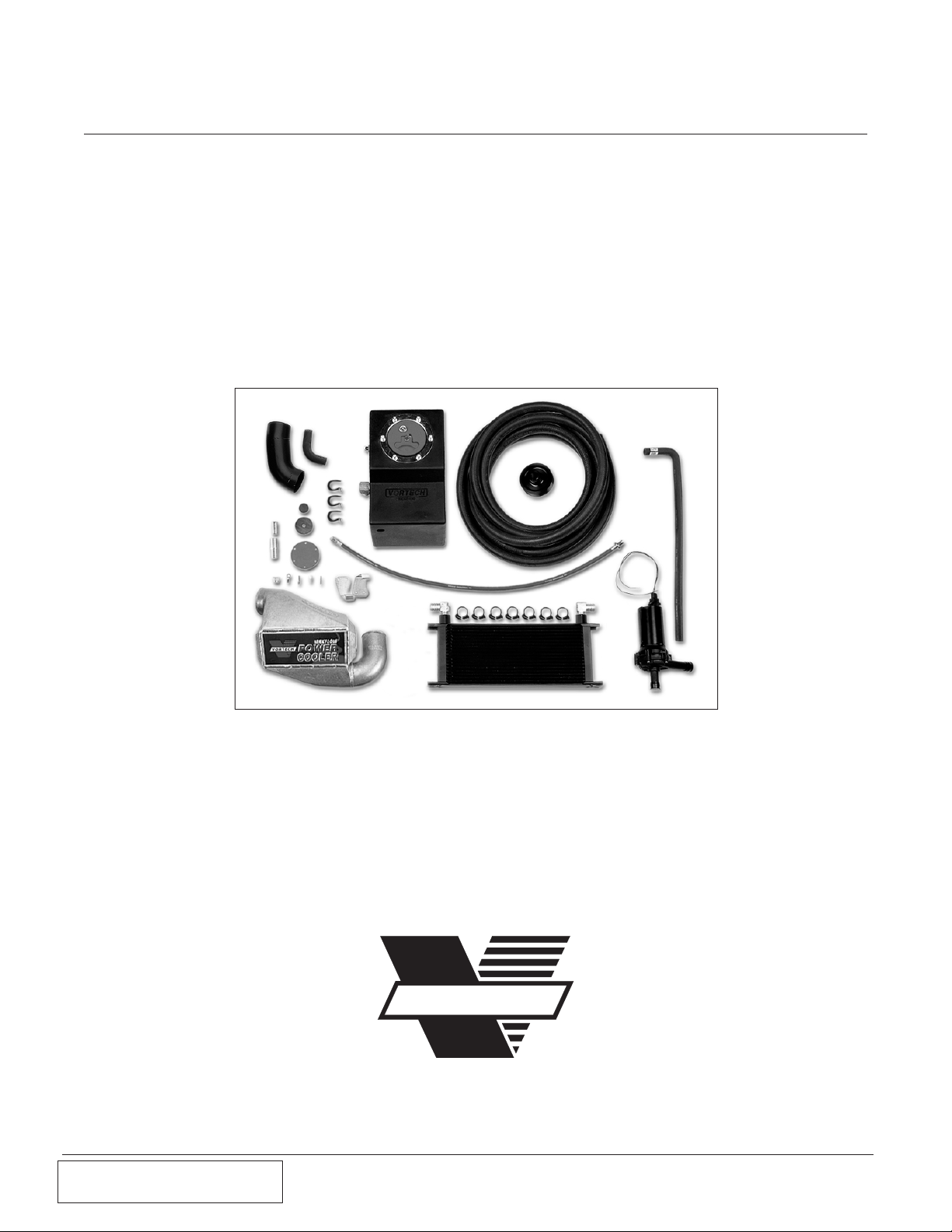
Maxflow®Power Cooler
®
Installation Instructions
1996 - 2001 Ford 4.6 Mustang GT (2 Valve)
P/N: 8N301-030 CARB EO #D-213-15 (1996-1998 Models only)
1650 Pacific Avenue, Channel Islands, CA 93033-9901 • Phone 805 247-0226
Fax: 805 247-0669 • www.vortechsuperchargers.com • M-F 8:00 AM - 4:30 PM (PST)
ENGINEERING, LLC
VORTECH
®
Page 2

P/N: 8N020-030
© 2002 Vortech Engineering, LLC
All Rights Reserved, Intl. Copr. Secured.
23JAN01 V2.1 (2V Maxflow Power Cooler.qxd)
ii
FOREWORD
Proper installation of this supercharger kit requires general automotive mechanic knowledge and experience. Please browse through each step of this instruction manual prior to
beginning the installation to determine if you should refer the job to a professional
installer/technician. Please call Vortech Engineering for installers in your area.
© 2001 VORTECH ENGINEERING, INC.
All rights reserved. No parts of this publication may be reproduced, transmitted, transcribed,
or translated into another language in any form, by any means without written permission
of Vortech Engineering, Inc.
Page 3

iii
P/N: 8N020-030
© 2002 Vortech Engineering, LLC
All Rights Reserved, Intl. Copr. Secured.
23JAN00 V2.1 (2V Maxflow Power Cooler.qxd)
Table Of Contents
FOREWORD . . . . . . . . . . . . . . . . . . . . . . . . . . . . . . . . . . . . . . . . . . . . . . .ii
TABLE OF CONTENTS . . . . . . . . . . . . . . . . . . . . . . . . . . . . . . . . . . . . . . .iii
NOTICES . . . . . . . . . . . . . . . . . . . . . . . . . . . . . . . . . . . . . . . . . . . . . . . . . .iv
TOOL AND SUPPLY REQUIREMENTS . . . . . . . . . . . . . . . . . . . . . . . . . . . .v
1. PREPARATION/REMOVAL . . . . . . . . . . . . . . . . . . . . . . . . . . . . . . . . . .1
2. SUPERCHARGER RECLOCKING AND REINSTALLATION . . . . . . . . .2
3. AFTERCOOLER AND DISCHARGE TUBE MOUNTING . . . . . . . . . . . .3
4. IDLE AIR CONTROL AND VALVE COVER VENT LINES . . . . . . . . . . . .4
5. WATER TANK MOUNTING (PLUMBING SCHEMATIC) . . . . . . . . . . . . .5
6. PLUMBING SCHEMATIC . . . . . . . . . . . . . . . . . . . . . . . . . . . . . . . . . . .6
7. WATER COOLER AND PUMP INSTALLATION . . . . . . . . . . . . . . . . . . .7
8. WATER PUMP WIRING . . . . . . . . . . . . . . . . . . . . . . . . . . . . . . . . . . . .8
9. FMU RECALIBRATION (1996-1998 Only) . . . . . . . . . . . . . . . . . . . . . . .9
10. FMU ASSEMBLY (1996-1998 Only) . . . . . . . . . . . . . . . . . . . . . . . . . . .10
11. FMU MOUNTING (1996-1998 Only) . . . . . . . . . . . . . . . . . . . . . . . . . . .11
12. FINAL CHECK . . . . . . . . . . . . . . . . . . . . . . . . . . . . . . . . . . . . . . . . . . .12
Page 4

P/N: 8N020-030
© 2002 Vortech Engineering, LLC
All Rights Reserved, Intl. Copr. Secured.
23JAN01 V2.1 (2V Maxflow Power Cooler.qxd)
iv
If the vehicle still has the battery located in the factory position, it must be relocated into the trunk to make room for the water tank assembly. Vortech part
number 8N150-010 is a Heavy-Duty Battery Relocation Kit that may be purchased separately. Commonly available “universal” relocation kits may be used
but they will most likely contain a smaller cable. Additional fabrication may also
be necessary when using a “universal” kit.
This product may not be legal for use on public roads in all 50 states.
NOTICES
(Read before installation is started)
Included in this kit is a smaller than originally supplied supercharger pulley. This new pulley is recommended to achieve the best performance results. Removal of the factory
sealed pulley will reduce the supercharger warranty from three years to one year unless
the supercharger unit (with the original pulley still attached) and new pulley are sent into
Vortech for removal, installation and re-sealing. If the supercharger warranty is not a concern or if the supercharger warranty has expired, the pulley may simply be removed and
replaced with the new part supplied. Hammering/prying etc. on the supercharger and/or
pulley will cause damage to the parts. Light heating of the supercharger pulley with a
propane torch (if the pulley is tight on the shaft) will aid removal. A return authorization
number is required before the supercharger and pulley are sent into Vortech. Call the
Vortech service department at (805) 247-0226 for a return authorization number. Return
freight (ground) will be paid by Vortech.
This product is protected by state common law, copyright and/or patent. All legal
rights therein are reserved. The design, layout, dimensions, geometry, and engineering features shown in this product are the exclusive property of Vortech
Engineering, Inc. This product may not be copied or duplicated in whole or part,
abstractly or fundamentally, intentionally or fortuitously, nor shall any design,
dimension, or other information be incorporated into any product or apparatus
without prior written consent of Vortech Engineering, Inc.
Page 5

P/N: 8N020-030
© 2002 Vortech Engineering, LLC
All Rights Reserved, Intl. Copr. Secured.
23JAN00 V2.1 (2V Maxflow Power Cooler.qxd)
v
Vortech Maxflow Power Cooler
Installation Instructions
1996 - 2001 Ford 4.6 Mustang GT (2 Valve)
Before beginning this installation,
please read through this entire instruction booklet
The Vortech Maxflow Power Cooler system was designed as a street/strip oriented aftercooler, specifically for use on 1996 - 2001 Ford 4.6 Mustang vehicles
equipped with a Vortech supercharger producing up to approximately 580 horsepower.
As with any power enhancing product, this system is intended for use on healthy,
well-maintained engines. Vortech Engineering is not responsible for engine dam-
age. Installation on new vehicles will not harm or adversely affect the break-in
period so long as factory break-in procedures are followed.
For best performance and continued durability, please take a note of the following key points:
1. Use only premium grade fuel 92 octane or higher (R+M/2).
2. Always listen for any sign of detonation (pinging) and discontinue hard use (no boost)
until problem is resolved.
TOOL & SUPPLY REQUIREMENTS:
• Open End Wrenches (7/16”, 9/16”, 5/8”, 11/16”)
• 3/8” Ratchet
• 8mm, 13mm, 9/16”and 18mm Sockets
• 5/32”, 3/16”, 9/16” Allen Wrenches
• Flat #2 Screwdriver
• Phillips #2 Screwdriver
• Utility Knife
• Torque Wrench (in/lbs)
• Wire Cutters, Strippers and Crimpers
• Drill Motor
• 1/8”, #21 Drill Bits
• Tape Measure
• Ford Springlock 3/8” Fuel Fitting
Disconnect Tool
• Pipe Tape (Teflon)
• Adjustable Wrench
Congratulations on selecting the best performing and most
efficient aftercooler today... the Vortech Maxflow Power Cooler!
Page 6

vi
Page 7

P/N: 8N020-030
© 2002 Vortech Engineering, LLC
All Rights Reserved, Intl. Copr. Secured.
23JAN00 V2.1 (2V Maxflow Power Cooler.qxd)
Vortech Maxflow Power Cooler
Part No. 8N301-030
1996 - 2001 Ford 4.6 Mustang GT (2 Valve)
PARTS LIST
IMPORTANT: Before beginning installation, verify that all parts are included in the kit.
Report any shortages or damaged parts immediately.
Air/Water Aftercooler Assembly (8N201-030)
Water Cooler Assembly (8N106-030)
PART NUMBER DESCRIPTION QUANTITY
8N101-030 Air/Water Aftercooler 1
7P500-078 1/2” NPT x 3/4” Hose Fitting 2
8N012-050 Cooler Discharge Tube 4.6 2V 1
7S300-200 3” x 2” Sleeve 1
7R002-044 No. 44 Hose Clamps 2
PART NUMBER DESCRIPTION QUANTITY
8N006-010 Water Cooler 1
7P500-026 90° Brass Fittings 2
8N010-050 Mounting Tabs 2
7E010-075 #12 x 3/4 HXHD Sheet Metal 4
7J010-001 #10 Flat Washer 4
7A250-075 1/4-20 x 3/4 SHCS 5
7F250-021 1/4-20 Nylock 5
7J250-001 1/4” Flat Washer 10
Water Pump Assembly (8N107-020)
PART NUMBER DESCRIPTION QUANTITY
5W001-011 14-16 GA Eyelet 1
5W001-012 18-22 GA Butt Connector 1
5W018-010 18 GA Wire Red (99”) 1
5W001-019 12 GA Butt Connector 1
5W001-014 Fuse Holder 1
5W001-015 Fuse Blade Style 1
5W001-002 Fuse Tap 1
5W001-040 12-10 GA Female Slide 1
8F001-402 Pump, Water 1
7E010-075 #12 x 3/4” Sheet Metal Screw 2
7J010-001 #10 Flat Washer 2
7U133-060 3/4” x 90° Hose Elbow 1
7R003-027 Adel Clamp 1
Water Tank Assembly (8N105-030)
PART NUMBER DESCRIPTION QUANTITY
8N105-010 Water Tank w/Fittings 1
7U038-000 3/4” Heater Hose (228”) 1
7R007-001 Plastic Double Grip Clamps 7
7R003-016 15/16” Adel Clamps 3
7E010-075 #12 x 3/4 HXHD 3
7J010-001 #10 Flat Washer 3
7U100-044 Nylon Tie Wraps 4” 16
7U100-066 Nylon Tie Wraps 11” 6
Support Components (8N104-020)
PART NUMBER DESCRIPTION QUANTITY
4FH145-050 30” Male Fuel Line 1
7U030-046 5/32” Vac Line (30”) 1
7U133-024 5/8” x 24-90° (Modified) 1
7P625-002 5/8” Hose Mendor 1
7P375-075 3/4” Hose Mendor 1
7U030-065 3/4”90° (Modified) 1
7U100-030 O-Ring FMU 1
6Z020-130 Small Diaphragm 1
6Z060-181 Valve Disk 1
6Z170-020 8:1 Ring Spacer Assembly 1
2A036-333 3.33 Supercharger Pulley 1
vii
Page 8

P/N: 8N020-030
© 2002 Vortech Engineering, LLC
All Rights Reserved, Intl. Copr. Secured.
23JAN01 V2.1 (2V Maxflow Power Cooler.qxd)
viii
Page 9

P/N: 8N020-030
© 2002 Vortech Engineering, LLC
All Rights Reserved, Intl. Copr. Secured.
23JAN00 V2.1 (2V Maxflow Power Cooler.qxd)
1
1. Preparation and Removal
A. Disconnect and remove the battery (if located in
the factory position, the battery will need to be
relocated to the trunk).
B. Remove the supercharger discharge tube and
bypass valve assembly.
C. Remove belt, supercharger and bracket.
Disassemble the bracket from the supercharger.
D. Disconnect lines from the air inlet that connects to
the idle air control and valve cover vent.
E. 1996-1998 Models Only: Remove the FMU from
the inner fender and disconnect the male fuel line
from the fuel rail.
NOTE: Temporarily cap oil feed and oil drain to
protect your engine from foreign particles.
*
*
*
*
* Ignore these steps and refer to the supercharger kit
instruction manual if the Power Cooler is being installed
at the same time as the supercharger kit.
Page 10

2
P/N: 8N020-030
© 2002 Vortech Engineering, LLC
All Rights Reserved, Intl. Copr. Secured.
23JAN00 V2.1 (2V Maxflow Power Cooler.qxd)
2. Supercharger Reclocking and Reinstallation
A. Loosen and remove the six (6) 1/4-20 cap screws
and retaining plates that hold the compressor
housing to the gearcase.
B. Carefully rotate the supercharger volute to the
specified location as shown. (See Figure 2-a.)
C. Evenly retighten the six (6) cap screws, torque to
60 in/lbs (5ft/lbs).
D. Remove original 3.60” supercharger pulley from
the supercharger and install the supplied 3.33” pulley.
E. Reattach the supercharger onto the bracket and
then remount the assembly to the engine.
Reconnect oil feed and drain lines.
NOTE: Included in this kit is a smaller than origi-
nally supplied supercharger pulley. This
new pulley is recommended to achieve
best performance results. Removal of the
factory sealed pulley will reduce the
supercharger warranty from three years
to one year unless the supercharger unit
(with the original pulley still attached) and
new pulley are sent into Vortech for
removal, installation and re-sealing. If
supercharger warranty is not a concern
or if the supercharger warranty has
expired, the pulley may simply be
removed and replaced with the new part
supplied. Hammering/prying etc. on the
supercharger and/or pulley will cause
damage to the parts. Light heating of the
supercharger pulley with a propane torch
(if the pulley is tight on the shaft) will aid
removal. A return authorization number is
required before the supercharger and
pulley are sent into Vortech. Call the
Vortech service department at (805) 2470226 for return authorization number.
Return freight (ground) will be paid by
Vortech.
NOTE: If the compressor housing does not rotate
freely relative to the gearcase, DO NOT
FORCE IT. SERIOUS SUPERCHARGER
DAMAGE MAY OCCUR. The machined
mating surfaces are designed to prevent
pressurized air from escaping and have
minimal tolerances. If the housing will not
move or is very tight, contact Vortech
Engineering immediately at (805) 2470226 and ask for our service department
for further assistance.
Figure 2-a
NOTE: Ignore this section if the Power Cooler is
being installed at the same time as the
supercharger kit.
Modified Clocking
Page 11

P/N: 8N020-030
© 2002 Vortech Engineering, LLC
All Rights Reserved, Intl. Copr. Secured.
23JAN00 V2.1 (2V Maxflow Power Cooler.qxd)
3
3. Aftercooler and Discharge Tube Mounting
A. Install the bypass valve onto the 1” cooler inlet
barb using the original hose. Secure the assembly
to the aftercooler.
B. Remove the silicone sleeves and clamps from the
original discharge tube.
C. Reinstall the 2-3/4” diameter silicone sleeve onto
the supercharger outlet and slide the sleeve back
as far as possible, leaving the two #44 hose
clamps loose.
D. Slide the 3” silicone sleeves (1 supplied, 1 original)
onto the throttle body and aftercooler outlet. Leave
the four #48 hose clamps loose.
E. With cooler into position, slide the silicone sleeve
and clamps from the supercharger outlet onto the
aftercooler inlet and secure.
F. Install the discharge tube between aftercooler and
throttle body and secure sleeves and clamps. (See
Figure 3-a.)
G. Reconnect the bypass valve outlet to the 90° plas-
tic elbow on the air inlet and secure with the original hose clamps. A small amount of trimming to
the 1” hose may be necessary to ensure proper fit.
Figure 3-a
*
* Ignore these steps and refer to the supercharger kit
instruction manual if the Power Cooler is being installed
at the same time as the supercharger kit.
Page 12

4
P/N: 8N020-030
© 2002 Vortech Engineering, LLC
All Rights Reserved, Intl. Copr. Secured.
23JAN00 V2.1 (2V Maxflow Power Cooler.qxd)
A. Using the 3/4” 90° elbow slide the shortest end
onto the 3 1/2” x 45° inlet elbow and insert the 3/4”
hose union into the opposite end.
B. Cut a piece of 3/4” hose 34” in length and attach
to the 3/4” hose union and to the idle air control
motor.
C. Attach the short end of the 5/8” x 24” 90° hose to
the 3 1/2” x 45° inlet elbow and install the 5/8”
hose union into the free end (see Figure 4-a).
D. Connect the valve cover vent line to the 5/8” hose
union and trim the excess line as needed (see
Figure 4-b).
4. Idle Air Control and Valve Cover Vent Lines
Figure 4-a
1996-1998 Models
Figure 4-b
Figure 4-c
1999-2001 Models
Page 13

5
P/N: 8N020-030
© 2002 Vortech Engineering, LLC
All Rights Reserved, Intl. Copr. Secured.
23JAN00 V2.1 (2V Maxflow Power Cooler.qxd)
5. Water Tank Mounting (Plumbing Schematic)
A. Remove battery tray and notch to allow tank
to sit flush with bottom of tray and reinstall
(see Figure 5-a).
B. Place the water tank in the tray previously occu-
pied by the battery and secure using the original
battery hold down (see Figure 5-b).
C. Cut a piece of the 3/4” hose 50” in length and
attach to the 3/4” 90° fitting (located at the lower
rear of the water tank). Route downward and
toward the front of the car (see Figure 5-e on the
next page).
D. Cut a piece of the 3/4” hose 98” in length and
attach it to the water return fitting on the tank.
Route the hose downward and secure with the
supplied adel clamps and #12 hardware to the
bottom of the radiator core support (see Figure
5–c). Connect the hose to the outlet fitting on the
aftercooler routing it up and through the headlight
well (see Figure 5-d).
Figure 5-a
Figure 5-b
Figure 5-c
Figure 5-d
Page 14

P/N: 8N020-030
© 2002 Vortech Engineering, LLC
All Rights Reserved, Intl. Copr. Secured.
23JAN00 V2.1 (2V Maxflow Power Cooler.qxd)
6
5. Water Tank Mounting, cont’d (Plumbing Schematic)
Figure 5-e
FROM
SUPERCHARGER
FRONT VIEW OF COOLER
TO THROTTLE BODY
WATER
INLET
WATER
OUTLET
Water Out
Flow
Water In
Flow
42"
FROM
SUPERCHARGER
TOP VIEW
BLUE/GREEN
(-)
BROWN/BLACK
WATER
COOLER
(+)
DRAINCOCK
WATER
PUMP
3/4” 90°
HOSE BEND
RETURN WATER FROM
AFTERCOOLER CORE
WATER
TANK
WATER
FLOW
50"
FEEDHOSE
FROM TANK
98"
FRONT OF VEHICLE
SECURE TO THE BOTTOM
OF THE RADIATOR CORE
SUPPORT
Page 15

P/N: 8N020-030
© 2002 Vortech Engineering, LLC
All Rights Reserved, Intl. Copr. Secured.
23JAN00 V2.1 (2V Maxflow Power Cooler.qxd)
7
A. Remove the air dam from the lower radiator
core support.
B. Loosely attach the supplied water cooler brackets
to the cooler using the supplied 1/4” hardware
(see Fig. 6-b). Following the photo, position the
cooler on the core support as far towards the passenger side as possible. Using the mounted cooler
brackets as a guide, mark the position on the
lower radiator core support where the bracket
mounting holes must be drilled (see Fig. 6-a). Drill
the four mounting holes and attach the cooler
assembly to the core support with #12 hardware.
C. Notch the air dam to allow clearance for the cooler
mounting brackets and reinstall.
D. Route the previously attached 50” section of hose
extending downward from the lower 90° fitting on
the water tank to the inlet of the water pump.
Secure hose with nylon ratchet clamps.
E. Secure the hoses to the chassis with provided tie
wraps.
F. Cut a piece of the 3/4” hose 42” in length and
attach to the outlet fitting of the water cooler.
Connect hose to the inlet fitting on the aftercooler.
The line should run parallel with the return line.
Trim the ends appropriately and secure both with
nylon ratchet clamps.
G. Following Figs. 6-b and 6-c, attach the supplied
rubber 90° hose bend to the water cooler inlet.
Slide the water pump bracket onto the water pump
and position the outlet of the pump in line with the
90° hose bend. Using the bracket as a guide, mark
and drill holes in core support and attach with the
supplied hardware. Trim the 90° hose if necessary,
and secure with nylon ratchet clamps.
NOTE: Hoses must not be kinked or restricted.
Route away from moving parts and direct
engine heat.
6. Water Cooler and Pump Installation
Figure 6-a
Water Pump Outlet
Figure 6-c
Water Pump Inlet
Figure 6-b
Page 16

P/N: 8N020-030
© 2002 Vortech Engineering, LLC
All Rights Reserved, Intl. Copr. Secured.
23JAN00 V2.1 (2V Maxflow Power Cooler.qxd)
8
7. Water Pump Wiring
A. Cut the supplied wiring harness plug from the end
at the water pump harness. Attach a 16 GA eyelet
to the brown/black wire (negative) and route to a
clean ground free from paint and vehicle undercoating. A cooler mounting tab works well for this.
B. Route the red wire from the water pump through
the firewall to the fuse panel. Connect to fuse #18
using the supplied fuse tap, fuse and fuse holder
(make sure that the supplied secondary fuse is
spliced into the power wire). Secure the red wire to
the chassis using the provided tie wraps. Connect
the red wire using a solderless connector to the
black wire with a yellow stripe or blue/green wire
(positive) on the wiring harness of the water pump.
C. Fill the water tank with 25% antifreeze and 75%
water to approximately 3” from the top. Do not fill
past the water return fitting (doing so will not allow
system to purge itself of air).
D. Turn the ignition key to the “ON” position and
check that the water is flowing through the system.
Once water is flowing, allow to run for approximately one minute. This will allow any trapped air
to be purged from the system. Once all the air is
removed, fill the tank to one inch below the filler
ring.
NOTE: Do not attach the red wire to the power
until the water tank is full of water, running
the water pump without water will lead to
premature failure and void your warranty.
NOTE: In some cases, the water pump must be
primed on initial start-up. This may be
accomplished by turning on the pump,
removing the RETURN line from the tank
and providing light suction on the hose to
remove the air in the system.
Page 17

P/N: 8N020-030
© 2002 Vortech Engineering, LLC
All Rights Reserved, Intl. Copr. Secured.
23JAN00 V2.1 (2V Maxflow Power Cooler.qxd)
9
8. FMU Recalibration (1996-1998 MODELS ONLY)
A. Remove the six (6) allen head screws on top of
the fuel management unit (FMU).
B. Remove the diaphragm and washer (and the ring,
if equipped) from inside of the FMU.
C. Remove the four screws holding the valve body.
Once taken apart, remove the piston, small
diaphragm, disk and O-ring.
D. Remove and exchange fittings on the valve body.
A small amount of Teflon sealant (not silicone or
RTV) may be used on the fittings. Excessive
sealant may damage the FMU.
E. Install the new O-ring, disk and small diaphragm
as shown. The disk must be centered on the valve
body. The disk should not be allowed to make
contact with the screws as this can damage it,
resulting in FMU leakage and/or malfunction.
F. Before tightening the valve bodyscrews, install the
piston with the radius side down. Apply a small
amount of pressure on the piston to eliminate any
possibility of an air bubble being trapped between
the disk and diaphragm.
G. Tighten the four screws to 24in/lbs (2ft/lbs) in a
crisscross pattern to ensure a proper seal.
H. Install the replacement ring (with the notched part
facing down) around the four screws inside the
FMU.
I. Place the new washer inside the ring on top of the
piston.
J. Install the new diaphragm and carefully line up
holes to the body.
K. Reinstall the FMU cover with the six (6) allen head
screws. DO NOT OVERTIGHTEN THE SCREWS.
The correct torque is 24in/lbs (2ft/lbs).
NOTE: If you are unsure of your ability to correctly
complete these steps, please contact
Vortech Engineering at (805)247-0226 and
ask for the Service Department.
NOTE: Ignore this section if the Power Cooler is
being installed at the same time as the
supercharger kit.
Page 18

P/N: 8N020-030
© 2002 Vortech Engineering, LLC
All Rights Reserved, Intl. Copr. Secured.
23JAN00 V2.1 (2V Maxflow Power Cooler.qxd)
10
8. FMU Recalibration, cont’d (FMU Assembly)
Figure 8-a
1996-1998 Models Only
COVER W/FITTING
DIAPHRAGM (LARGE)
RING SPACER
(NOTCH DOWN)
WASHER
FLARE FITTING
PISTON
TEFLON SEALANT
ON THESE
THREADS ONLY
10
O-RING
VALVE BODY
90° FLARE FITTING
© 1999 VORTECH ENGINEERING, INC.
All Rights Reserved, Intl. Copr. Secured
HOUSING
VALVE DISK
DIAPHRAGM (SMALL)
Page 19

P/N: 8N020-030
© 2002 Vortech Engineering, LLC
All Rights Reserved, Intl. Copr. Secured.
23JAN00 V2.1 (2V Maxflow Power Cooler.qxd)
11
9. FMU Mounting (1996-1998 Models Only)
A. Install the new 30” long male FMU line to the fuel
rail and to the FMU.
B. Remount the FMU next to the air inlet (see Figure
9-a).
C. Connect the supplied length of 5/32” vacuum hose
to the FMU and the original manifold vacuum
source.
D. Route the 5/32” vacuum line from the bypass valve
and TEE into the FMU vacuum line with the original 5/32” TEE. Make sure vacuum line to bypass
valve is not kinked.
Figure 9-a
Page 20

12
P/N: 8N020-030
© 2002 Vortech Engineering, LLC
All Rights Reserved, Intl. Copr. Secured.
23JAN00 V2.1 (2V Maxflow Power Cooler.qxd)
10. Final Check
A. Check all fittings, hose and clamps for tightness
and leaks. Make sure all wires and lines are properly secure with clamps or tie wraps.
B. Make sure all wires and hoses are routed away
from hot, moving or sharp objects.
C. Double check to ensure water is flowing through
the system.
ENGINEERING, INC.
WARNING: Do not attempt to operate the vehicle until
ALL components are installed and ALL
operations are completed including the
final check.
1650 Pacific Avenue, Channel Islands, CA 93033-9901 • Phone 805 247-0226
Fax: 805 247-0669 • www.vortechsuperchargers.com • M-F 8:00 AM - 4:30 PM (PST)
VORTECH
®
 Loading...