

Page 1
GM F-Body LT1
Supercharger System
Installation Instructions
50 State Smog Legal per CARB EO #D-213-17
1993-1997 Model Years
1650 PACIFIC AVENUE • CHANNEL ISLANDS, CA 93033-9901 • (805) 247-0226
FAX (805) 247-0669 • www.v ortechsuperchargers.com • M-F 8:00 AM - 4:30 PM PST
P/N: 4GH020-010
©2003 Vortech Engineering, LLC
All Rights Reserved, Intl. Copr. Secured
05NOV01 v1.2
(4GH V1.2)
®
ENGINEERING, LLC
Page 2

FOREWORD
Proper installation of this supercharger kit requires general automotive mechanic
knowledge and experience. Please browse through each step of this instruction
manual
job to a professional installer/technician. Please call Vortech Engineering for
possible installers in your area.
prior
to beginning the installation to determine if you should refer the
© 2001 VORTECH ENGINEERING, LLC
All rights reserved. No part of this publication may be reproduced, transmitted, transcribed,
or translated into another language in any form, by any means without written permission
of Vortech Engineering, LLC.
P/N: 4GH020-010
©2003 Vortech Engineering, LLC
All Rights Reserved, Intl. Copr. Secured
05NOV01 v1.2
(4GH V1.2)
ii
Page 3

Table Of Contents
FOREW0RD............................................................................................................i
TABLE OF CONTENTS ..........................................................................................ii
IMPORTANT NOTICES ........................................................................................... iii
1993 GM LT1 F-BODY SUPPLEMENT...................................................................iv
1994-95 GM LT1 F-BODY SUPPLEMENT..............................................................v
1996-97 GM F-BODY SUPPLEMENT ....................................................................vi
CARROLL SUPERCHARGING MAF SIGNAL MASSAGER...................................vii
CRANE IGNITION SYSTEM ...................................................................................viii
TOOL AND SUPPLY REQUIREMENTS..................................................................ix
PARTS LIST - 1993 GM LT1 F-BODY.....................................................................x
PARTS LIST - 1994-97 GM LT1 F-BODY ...............................................................xi
1. PREPARATION/REMOVAL ..........................................................................1
2. OIL COOLER LINE MODIFICATIONS .........................................................2
3. CRUISE CONTROL RELOCATION .............................................................4
3. SPLASH GUARD TEMPLATE......................................................................5
4.1 AIR PUMP MODIFICATION AND RELOCATION (1993 ONLY)...................6
4.2 AIR PUMP MODIFICATION AND RELOCATION (1994-97 ONLY)..............7
5. OIL FEED LINE ............................................................................................9
6. OIL DRAIN LINE...........................................................................................10
7. SUPERCHARGER MAIN BRACKETS.........................................................11
8. SUPERCHARGER MOUNTING...................................................................11
9. HARMONIC BALANCER, PULLEYS AND DRIVE BELT .............................12
10. AIR INLET DUCT .........................................................................................13
11. OIL DRAIN HOSE.........................................................................................14
12. OIL FEED HOSE CONNECTION.................................................................14
13. COIL RELOCATION AND IGNITION BOX MOUNTING...............................14
14. IGNITION/BOOST CONTROL OPERATION................................................16
15. SUPERCHARGER DISCHARGE ASSEMBLY.............................................17
16. INTAKE AIR TEMPERATURE (IAT) SENSOR THREADING .......................17
17. BYPASS VALVE CONNECTION ..................................................................17
18. FUEL MANAGEMENT UNIT (FMU) INSTALLATION ...................................18
19. BREATHER HOSE RE-ROUTING ...............................................................19
20. T-REX FUEL PUMP INSTALLATION............................................................19
T-REX FUEL PUMP TEMPLATE..................................................................21
21. FUEL INJECTOR REPLACEMENT (1993 MODELS ONLY)........................22
22. FINAL CHECK..............................................................................................23
©2003 Vortech Engineering, LLC
iii
All Rights Reserved, Intl. Copr. Secured
P/N: 4GH020-010
05NOV01 v1.2
Page 4

GM F-BODY LT1
IMPORTANT
NOTICES
This product is protected by state common law, copyright and/or patent.
All legal rights therein are reserved. The design, layout, dimensions,
geometry, and engineering features shown in this product are the exclusive
property of Vortech Engineering, Inc. This product may not be copied or
duplicated in whole or part, abstractly or fundamentally, intentionally or
fortuitously, nor shall any design, dimension, or other information be
incorporated into any product or apparatus without prior written consent
of Vortech Engineering, LLC.
This kit is not designed to fit onto vehicles equipped with the factory
traction control option. If you are installing this kit on one of these vehicles,
additional non-Vortech parts are required. Call Vortech for further details.
P/N: 4GH020-010
©2003 Vortech Engineering, LLC
All Rights Reserved, Intl. Copr. Secured
05NOV01 v1.2
(4GH V1.2)
iv
Page 5
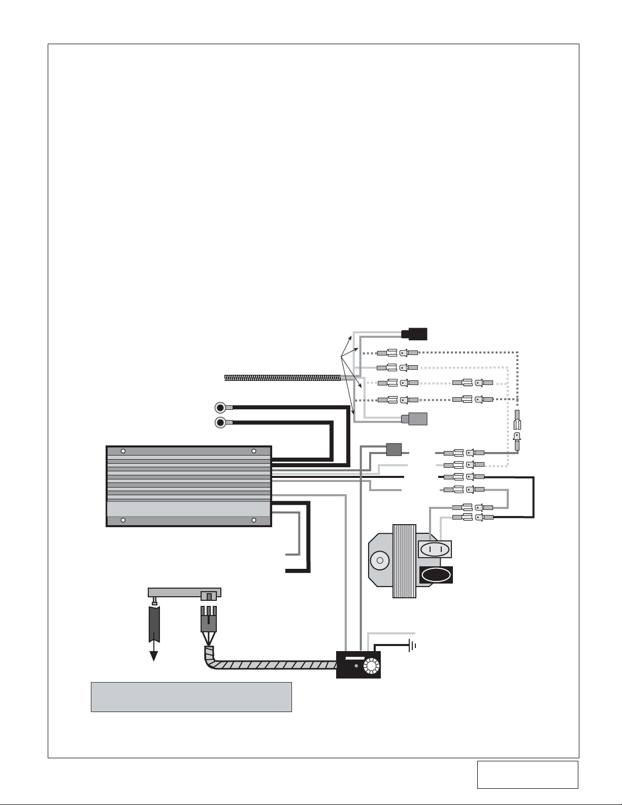
1993 GM LT1 F-BODY SUPPLEMENT
HARDWIRING INSTRUCTIONS FOR KITS NOT
EQUIPPED WITH A GM WIRING HARNESS
1. Unplug the grey and black connectors from the coil.
Cut the connectors off from the main harness
approximately 2" from the end.
2. Attach the supplied male and female connectors to
lengthen the white and pink wires previously cut from
the coil connectors. Connect the two pink wires together
to one red wire and the two white wires to the supplied
single white wire. Attach the pink and white wires to the
red and white wires on the supplied ignition box.
3. Reattach the grey connector to the coil (leave the black
connector disconnected). Using the supplied male and
female connectors, attach the pink wire on the grey
connector to the orange wire on the supplied ignition
box and attach the white wire to the black wire on the
ignition box.
WHITE OR
GREEN
X
FACTORY GM
HARNESS
(UNPLUGGED
FROM COIL)
TO BATTERY +
TO GROUND
RANE
®
cams
HI-6R
C
*GREY MAGNETIC TRIGGER HARNESS (TAPE UP)
CAPACITIVE DISCHARGE IGNITION
WITH AUTO-SEQUENCE REV LIMITER
GREEN TACH (TAPE UP)
SUPPLIED MAP SENSOR
HEAVY RED
HEAVY BLACK
CUT
HERE
PINK
X
X
WHITE
X
PINK
IGNITION COIL
WIRE TAP
BLACK CONNECTOR
RED
WHITE
WHITE
RED
GREY CONNECTOR
RED
WHITE
BLACK
ORANGE
PINK
WHITE
BLACK
ORANGE
GREY
TERMINAL
NO CONNECTIONS
AT BLACK TERMINAL
3 WIRE HARNESS
MANIFOLD
VACUUM
*NOTE: CABLE CONTAINS RED AND BLACK
LEADS. MAKE SURE LEADS DO NOT CONTACT
EACH OTHER AND SHORT UNIT WHEN TAPING UP .
v
YELLOW (TAPE UP)
BROWN WITH WHITE STRIPE
RED
RANE
T
E
ELECTRONICS
R
C
HI-6TR
TIMING RETARD CONTROL
A
R
D
BLACK (GROUND)
©2003 Vortech Engineering, LLC
All Rights Reserved, Intl. Copr. Secured
P/N: 4GH020-010
05NOV01 v1.2
Page 6
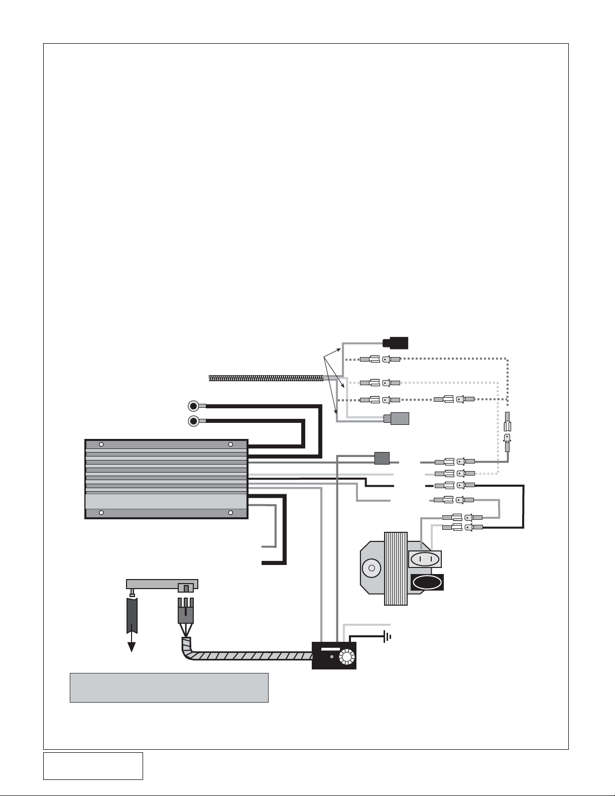
1994-95 GM LT1 F-BODY SUPPLEMENT
HARDWIRING INSTRUCTIONS FOR KITS NOT
EQUIPPED WITH A GM WIRING HARNESS
1. Unplug the grey and black connectors from the coil.
Cut the connectors off from the main harness
approximately 2" from the end.
2. Attach the supplied male and female connectors to
lengthen the white and pink wires previously cut from
the coil connectors. Connect the two pink wires
together to one red wire. Attach the pink and white
wires to the red and white wires on the supplied ignition
box.
3. Reattach the grey connector to the coil (leave the black
connector disconnected). Using the supplied male and
female connectors, attach the pink wire on the grey
connector to the orange wire on the supplied ignition
box and attach the white wire to the black wire on the
ignition box.
FACTORY GM
HARNESS
(UNPLUGGED
FROM COIL)
TO BATTERY +
TO GROUND
RANE
®
cams
MANIFOLD
VACUUM
HI-6R
C
*GREY MAGNETIC TRIGGER HARNESS (TAPE UP)
*NOTE: CABLE CONTAINS RED AND BLACK
LEADS. MAKE SURE LEADS DO NOT CONTACT
EACH OTHER AND SHORT UNIT WHEN TAPING UP .
CAPACITIVE DISCHARGE IGNITION
WITH AUTO-SEQUENCE REV LIMITER
GREEN TACH (TAPE UP)
HEAVY RED
HEAVY BLACK
SUPPLIED MAP SENSOR
3 WIRE HARNESS
PINK
CUT
HERE
X
X
WHITE
X
PINK
WIRE TAP
IGNITION COIL
BROWN WITH WHITE STRIPE
RED
RANE
A
R
T
E
D
ELECTRONICS
R
C
HI-6TR
TIMING RETARD CONTROL
BLACK CONNECTOR
RED
WHITE
RED
GREY CONNECTOR
RED
WHITE
BLACK
ORANGE
PINK
WHITE
GREY
TERMINAL
NO CONNECTIONS
AT BLACK TERMINAL
YELLOW (TAPE UP)
BLACK (GROUND)
BLACK
ORANGE
P/N: 4GH020-010
©2003 Vortech Engineering, LLC
All Rights Reserved, Intl. Copr. Secured
05NOV01 v1.2
(4GH V1.2)
vi
Page 7

1996-97 GM LT1 F-BODY SUPPLEMENT
HARDWIRING INSTRUCTIONS FOR KITS NOT
EQUIPPED WITH A GM WIRING HARNESS
1. Unplug the two-wire harness from the coil. Cut the
connectors off from the main harness approximately 2"
from the end.
2. Attach the supplied male and female connectors to the
green and pink wires previously cut from the coil
connector. Connect the pink wire to the red wire and
the green wire to the white wire coming from the
supplied ignition box.
3. Reattach the grey connector to the coil. Using the
supplied male and female connectors, attach the pink
wire to the orange wire (from the ignition box) and attach
the green wire to the black wire.
CUT HERE
AND ATTACH
CONNECTOR
FACTORY GM
TO BATTERY +
TO GROUND
HARNESS
(UNPLUGGED
FROM COIL)
GREEN
HEAVY RED
HEAVY BLACK
X
PINK
X
RANE
®
cams
MANIFOLD
VACUUM
HI-6R
C
*GREY MAGNETIC TRIGGER HARNESS (TAPE UP)
*NOTE: CABLE CONTAINS RED AND BLACK
LEADS. MAKE SURE LEADS DO NOT CONTACT
EACH OTHER AND SHORT UNIT WHEN TAPING UP .
CAPACITIVE DISCHARGE IGNITION
WITH AUTO-SEQUENCE REV LIMITER
GREEN TACH (TAPE UP)
SUPPLIED MAP SENSOR
3 WIRE HARNESS
WIRE TAP
RED
WHITE
BLACK
ORANGE
IGNITION COIL
YELLOW (TAPE UP)
BROWN WITH WHITE STRIPE
RED
RANE
ELECTRONICS
C
HI-6TR
TIMING RETARD CONTROL
A
R
T
E
D
R
BLACK (GROUND)
PINK
GREEN
vii
©2003 Vortech Engineering, LLC
All Rights Reserved, Intl. Copr. Secured
P/N: 4GH020-010
05NOV01 v1.2
Page 8

SPECIAL NOTICE CONCERNING THE
Carroll Supercharging
MAF Signal Massager
1996-97 LT1 F-Bodies may require the Carroll Supercharging
MAF Signal Massager to prevent OBD-II trouble codes from
being set. This par t is available separately at an additional
cost under P/N 4GM020-030 direct from Vortech Engineering,
Inc. The MAF Signal Massager, manufactured by Carroll
Supercharging Co., Inc., is serviced exclusively by the
manufacturer. Carroll Supercharging Co., Inc. warrants this
product to be free from defects in material and workmanship
under normal use and if properly installed for 90 days. In case
of malfunction, this unit will be repaired free of charge according
to the terms of the warranty. If found to be defective as
mentioned above, it will be repaired or replaced if returned
prepaid along with proof of date of purchase. This shall
constitute the sole remedy of the purchaser and the sole liability
of Carroll Supercharging Co., Inc. and/or Vortech Engineering,
Inc. To the extent permitted by law, the foregoing is exclusive
and in lieu of all other warranties or representations whether
expressed or implied, including any implied warranty of
merchantability or fitness. In no event shall Carroll
Supercharging Co., Inc. and/or Vortech Engineer ing, Inc., be
liable for labor charges, special or consequential damages.
When returning this unit for service, proof of purchase must be
supplied for warranty verification. Please send the unit prepaid with proof of purchase to the attention of:
Carroll Supercharging Co., Inc.
Customer Service Department
14 Doty Rd.
Haskell, NJ 07420
(973) 835-1705
(973) 835-1660 Fax
www. carrollsupercharging.com
The repaired unit will be returned as soon as possible after
receipt, COD for any charges. Be sure you include a detailed
account of any problems experienced, the type of vehicle and
any modifications.
Should you have any technical or installation questions
regarding this unit, contact Vortech Engineering, Inc., directly
at (805) 247-0226, M-F 8AM-4:30PM (PST).
P/N: 4GH020-010
©2003 Vortech Engineering, LLC
All Rights Reserved, Intl. Copr. Secured
05NOV01 v1.2
(4GH V1.2)
viii
Page 9

SPECIAL NOTICE CONCERNING THE
CRANE IGNITION SYSTEM
The ignition system, manufactured by Crane Electronics,
included in this kit is serviced exclusively by the manuf acturer.
Crane Electronics warrants this product to be free from defects
in material and workmanship under normal use and if properly
installed for a period of one (1) year from the date of purchase.
In case of malfunction, this unit will be repaired free of charge
according to the terms of the warranty. If found to be def ectiv e
as mentioned above, it will be repaired or replaced if returned
prepaid along with proof of date of purchase. This shall
constitute the sole remedy of the purchaser and the sole liability
of Crane Electronics and/or Vortech Engineering, Inc. To the
extent permitted by law, the foregoing is exclusive and in lieu
of all other warranties or representations whether expressed
or implied, including any implied warranty of merchantability
or fitness. In no event shall Crane Electronics and/or Vortech
Engineering, Inc., be liable for labor charges, special or
consequential damages.
When returning this unit for service, proof of purchase must be
supplied for warr anty verification. After the w arranty period has
expired, repair service is charged between a minimum and
maximum charge. In either case, please send the unit prepaid with proof of purchase to the attention of:
Crane Electronics
Customer Service Department
530 Fentress Boulevard
Daytona Beach, Florida, 32114
(904) 258-6174
(904) 258-6167 Fax
www.cranecams.com
The repaired unit will be returned as soon as possible after
receipt, COD for any charges. Be sure you include a detailed
account of any problems experienced, the type of vehicle and
any modifications.
Should you have any technical or installation questions
regarding this unit, contact Vor tech Engineering, Inc. directly
at (805) 247-0226, M-F 8AM-4:30PM (PST).
©2003 Vortech Engineering, LLC
ix
All Rights Reserved, Intl. Copr. Secured
P/N: 4GH020-010
05NOV01 v1.2
Page 10

1993 - 1997
GM LT1 F-Body
Installation Instructions
50 State Smog Legal per CARB EO #D-213-16
Congratulations on selecting the best performing and best supported automotive
supercharger available today... the VORTECH
Before beginning this installation, please read through this entire instruction booklet and the Street
Supercharger System Owner's Manual which includes the Limited Warranty Program and the Warranty
Registration form.
Vortech supercharger systems are performance improving devices. In most cases, increases in torque of 30%
to 35% and horsepower of between 35% and 45% can be expected with the boost levels specified by Vortech
Engineering, Inc. This product is intended for use on healthy, well maintained engines. Installation on a worn-out
or damaged engine is not recommended and may result in failure of the engine as well as the supercharger.
Vortech Engineering, Inc. is not responsible for engine damage.
Installation on new vehicles will not harm or adversely affect the break-in period so long as factory break-in
procedures are followed.
For best performance and continued durability, please take note of the following key points:
1. Use only premium grade fuel 92 octane or higher (R+M/2).
2. The engine must have stock compression ratio.
3. If the engine has been modified in any way, check with Vortech prior to using this product.
4. Always listen for any sign of detonation (pinging) and discontinue hard use (no boost) until problem is
resolved.
5. Perform an oil and filter change upon completion of this installation and prior to test driving your
vehicle. Thereafter, always use either a high grade SF rated engine oil or a high quality synthetic
lubricant, and change the oil and filter at least every 3,000 miles. Never attempt to extend the oil
change interval beyond 3,000 miles, regardless of oil manufacturer's claims, as potential damage
to the supercharger may result.
6. Before beginning installation, replace all spark plugs that are older than 1 year or 10,000 miles with
original heat range plugs as specified by the manufacturer and reset timing to factory specifications
(follow the procedures outlined in the factory repair manual and/or as indicated on the factory underhood
emissions tag). Do not use platinum spark plugs unless they are original equipment. Change
spark plugs every 15,000 miles and spark plug wires at least every 50,000 miles.
®
V-2® Supercharger!
TOOL & SUPPLY REQUIREMENTS
• Factory repair manual
• 3/8" socket and drive set: SAE & metric
• 1/2" breaker bar and 4" extension
• Flat #2 screwdriver
• Phillips #2 screwdriver
• Adjustable wrench
• Open end wrenches:
3/8", 7/16", 9/16", 5/8", 3/4", 7/8", 15mm, 10mm
• 1/8" drill bit
•2 gallons 50/50 coolant and water mix
•Tubing cutter
• Hose cutter or knife
• Loctite threadlocker
•5 quarts 20w/50 synthetic motor oil
• Spring-lock fitting disconnect tool
• Drill motor
• 1/2"-20 die
• Wire cutter/crimp tool
• 1/4" drill bit
• 5/16" allen wrench
Note: If your vehicle has in excess of 10,000 miles since its last spark plug change, then you will need:
• Spark plug socket
•8 - new OE heat range spark plugs
4GH218-050-15
4GH218-060-15
P/N: 4GH020-010
©2003 Vortech Engineering, LLC
All Rights Reserved, Intl. Copr. Secured
05NOV01 v1.2
(4GH V1.2)
x
Page 11
1993 GM LT1 F-Body
®
ENGINEERING, LLC
Part No. 4GH218-050SQ
PARTS LIST
IMPORTANT: Before beginning installation, verify that all parts are included in the kit. Report any shortages or damaged parts immediately.
Part Number Description Quantity
2E228-120 SUPERCHARGER ASSEMBLY 1
2E128-120 V-2 SQ Supercharger 1
4GH038-333 3.33” supercharger drive pulley 1
8R101-002 Pulley retainer assembly 1
4GH111-021 MOUNTING BRACKET ASSEMBLY 1
4GH010-034 Mounting plate A 1
4GH010-044 Mounting plate B 1
4GH011-021 Upper mounting bracket 1
4GH011-031 Lower mounting bracket 1
7A375-250 3/8-16 x 2-1/2” bolts 2
7J375-044 3/8" SAE washers 4
7A375-124 3/8-16 x 1-1/4” bolts 3
7K375-040 3/8” AN960 flat washers 10
7A375-075 3/8-16 x 3/4” bolts 4
7A375-100 3/8-16 x 1” bolts 4
7A312-100 5/16-18 X 1” bolts 2
7K312-001 5/16” AN washers 2
7L312-000 5/16" split lock washers 2
7F312-018 5/16-18 nuts 2
7A375-125 3/8-16 x 1-1/4” socket head cap screws 3
4GV011-032 Belt tensioner 1
7GL10-150 10M x 1.5 nylock nut 1
4GH112-010 AIR INTAKE ASSEMBLY 1
4GH012-012 Air inlet tube assembly 1
8H040-030 Air filter 1
7U035-000 3-1/2" x 17" flex hose 1
4FA012-012 90° intake elbow 1
7E010-075 #12 x 3/4" sheet metal bolts 4
7S350-200 3-1/2” x 2” sleeves 2
7R002-052 #52 hose clamps 2
7R002-056 #56 hose clamps 4
5W018-050 30" 18GA yellow wire 1
5W018-020 30" 18GA black wire 1
5W018-010 30" 18GA red wire 1
5W001-007 3/16" x 6" shrink tube 1
7P375-045 3/8" NPT 45° street elbow 1
7P375-017 3/8" NPT x 1/2" straight hose barb 1
7P125-025 1/8" NPT x 5/32" hose 1
4GH010-091 Air Inlet bracket 1
7P125-016 1/8" NPT plug 1
4GH013-010 Air filter cover 1
4GH130-036 OIL DRAIN ASSEMBLY 1
7U030-036 1/2” x 9” oil drain hose 1
7P375-017 3/8” NPT x 1/2” straight hose barb 1
7R001-008 #8 stainless hose clamps 2
4GH101-001 FUEL PUMP ASSEMBLY 1
5W001-001 Wire tap 1
5W001-012 22GA red solderless connector 1
5W001-014 Fuse holder 1
5W001-015 20A blade type fuse 1
5W001-017 Large ring terminals 2
5W001-011 Ring terminals 2
7F008-032 8-32 lock nuts 8
7J008-001 #8 flat washers 8
7J010-001 #10 flat washers 2
7R001-004 #4 hose clamps 2
7R004-002 17.0 stepless clamps 2
7U100-055 6" nylon tie wraps 10
8F101-300 Pump wiring assembly 1
7U032-016 3/8" x 36" fuel hose (pump inlet) 1
7U031-018 5/16" x 12" fuel hose 1
7U032-016 3/8" x 11" fuel hose (pump outlet) 1
7U314-001 #8 Lord mounts 4
8F002-265 Inline 90° T-Rex fuel pump 1
7P312-002 5/16" x 1/4" NPT barbs 2
7P250-045 1/4" NPT x 3/8" fittings 2
7R004-003 14.5 stepless clamps 2
7E010-046 #8 x 3/4" sheet metal screw 1
7U100-044 4" nylon tie wraps 10
4GH150-012 RELOCATION ASSEMBLY 1
4GH010-051 Bent coil mount bracket 1
7A375-075 3/8-16 x 3/4" bolts 2
7F375-016 3/8-16 nuts 2
7J375-044 3/8" SAE washers 2
7E010-150 #10 x 1-1/2" sheet metal bolts 2
7R001-008 #8 stainless hose clamps 4
7GL10-150 10M x 1.5" nylock nut 1
7R003-015 15/16" adel clamp 1
7U033-000 5/8" x 20" PVC hose 1
7U125-000 11-1/2" heat sleeve 1
7U133-024 5/8" x 2' molded elbow hose 1
7P375-020 3/8" NPT x 5/8" straight hose barb fittings 2
7P500-021 1/2" 90° compression fittings 2
7P625-005 5/8" 90° compression fittings 2
7P500-022 1/2" to 3/8" bushings 2
Part Number Description Quantity
4GH112-020 AIR DISCHARGE ASSEMBLY 1
4GH012-020 Discharge tube A 1
4GH012-010 Discharge tube B 1
7S350-300 3-1/2” x 3” sleeve 1
7S400-200 4” x 2” sleeve 1
7R002-044 #44 hose clamps 2
7R002-056 #56 hose clamps 2
7R002-064 #64 hose clamps 2
7S275-300 2-3/4” x 3” sleeve 1
7U034-016 1" x 2-1/2" heater hose 1
7U034-016 1" x 14" heater hose 1
7R002-016 #16 hose clamps 4
7U030-046 5/32" x 26" vacuum hose 1
7P156-082 5/32" tee 1
8D001-001 Bypass valve 1
7P750-100 3/4" NPT x 1" hose fitting 1
4GH116-010 CRANK PULLEY ASSEMBLY 1
4GH016-021 Crank pulley 1
4GH018-021 Factory crank pulley 1
7A437-175 7/16-14 x 1-3/4" bolts 3
7J438-081 7/16” SAE washers 3
7L437-075 7/16” lock washers 3
2A048-408 Belt 1
4GH130-026 OIL FEED ASSEMBLY 1
7U030-026 1/4” x 49” oil feed hose 1
7P525-067 .500 crimp ferrules 2
7P250-066 #4 swivel x 1/4” hose barb fittings 2
7P250-082 1/4 NPT x -4 90° fitting 1
7P250-122 1/4" pipe thread AN917 tee 1
7P125-026 1/8 NPT x #4 90° fitting 1
7P250-121 1/4" NPT x 3" steel nipple 1
7U100-055 6" nylon tie wraps 3
7U100-066 11" nylon tie wraps 2
7P250-080 1/4 NPT 90° street elbow 1
7P250-036 #4 flare to 1/4" NPT 1
7S625-000 32" fire sleeve 1
4GH139-096 PCV ASSEMBLY 1
7U375-052 3/8" vacuum cap 1
7U100-055 6" nylon tie wraps 5
7U030-036 1/2” x 58” oil drain hose 1
7R001-008 #8 stainless hose clamps 2
4GH238-058 FMU (with lines) 1
6Z110-118 10:1 fuel management unit 1
4GH145-156 14" male fuel line assembly 1
4GH146-166 10" female fuel line assembly 1
7P156-082 5/32" tee 1
7U030-046 5/32” x 36” vacuum line 1
7U100-055 6” nylon tie wraps 10
4GH136-060 SMOG PUMP RELOCATION 1
7U100-066 11" nylon tie wraps 8
7P625-004 5/8" tee 1
7R001-008 #8 stainless hose clamp 1
4GH010-061 Bent smog pump bracket 1
7A250-101 1/4-20 x 1" cap screws 3
7F250-021 1/4-20 nylock nuts 3
7J250-001 1/4" SAE washers 6
7E010-075 #12 x 3/4" sheet metal bolts 3
7U033-000 5/8" x 35" PVC hose 1
7U033-000 5/8" x 20" PVC hose 1
8H040-022 3/4" breather 1
5A101-008 HI-6 CRANE IGNITION ASSEMBLY 1
5A001-009 HI-6TR Crane ignition system 1
5W001-001 Wire tap 1
5W001-009 16-14GA male slides 11
5W001-010 16-14GA female slides 15
5W001-011 16-14GA eyelets 2
5W001-019 12-10GA solderless connectors 4
5W001-020 3/4" X 35" plastic wire loom 1
5W012-000 72" 12GA red wire 1
5W012-010 24" 12GA black wire 1
5W018-010 18" 18GA red wire 1
5W018-020 18" 18GA black wire 1
5W018-060 18" 18GA orange wire 1
5W022-060 77" 22GA blue wire 1
7E010-046 #8 x 3/4" sheet metal screws 2
7P156-082 5/32" tee 1
7U030-046 5/32" x 60" vacuum line 1
7U100-055 6" nylon tie wraps 6
7U375-001 9" Velcro hook 1
7U375-002 9" Velcro latch 1
5A002-001 GM Wiring harness 1
5W001-014 Fuse holder 1
5W001-015 Blade type 20A fuse 1
5W001-017 Large ring terminals 2
5A002-006 Map sensor 1
©2003 Vortech Engineering, LLC
xi
All Rights Reserved, Intl. Copr. Secured
P/N: 4GH020-010
05NOV01 v1.2
Page 12

1994-1997 GM LT1 F-Body
Part No. 4GH218-060SQ
®
ENGINEERING, LLC
PARTS LIST
IMPORTANT: Before beginning installation, verify that all parts are included in the kit. Report any shortages or damaged parts immediately.
Part Number Description Quantity
2E228-120 SUPERCHARGER ASSEMBLY 1
2E128-120 V-2 SQ supercharger 1
4GH038-333 3.33” supercharger drive pulley 1
8R101-002 Pulley retainer assembly 1
4GH111-021 MOUNTING BRACKET ASSEMBLY 1
4GH010-034 Mounting plate A 1
4GH010-044 Mounting plate B 1
4GH011-021 Upper mounting bracket 1
4GH011-031 Lower mounting bracket 1
7A375-250 3/8-16 x 2-1/2” bolts 2
7J375-044 3/8" SAE washers 4
7A375-124 3/8-16 x 1-1/4” bolts 3
7K375-040 3/8” AN960 flat washers 10
7A375-075 3/8-16 x 3/4” bolts 4
7A375-100 3/8-16 x 1” bolts 4
7A312-100 5/16-18 X 1” bolts 2
7K312-001 5/16” AN washers 2
7L312-000 5/16" split lock washers 2
7F312-018 5/16-18 nuts 2
7A375-125 3/8-16 x 1-1/4” socket head cap screws 3
4GV011-032 Belt tensioner 1
7GL10-150 10M x 1.5 nylock nut 1
4GH112-010 AIR INTAKE ASSEMBLY 1
4GH012-012 Air inlet tube assembly 1
8H040-030 Air filter 1
7U035-000 3-1/2" x 17" flex hose 1
4FA012-012 90° intake elbow 1
7E010-075 #12 x 3/4" sheet metal bolts 4
7S350-200 3-1/2” x 2” sleeves 2
7R002-052 #52 hose clamps 2
7R002-056 #56 hose clamps 4
5W018-050 30" 18GA yellow wire 1
5W018-020 30" 18GA black wire 1
5W018-010 30" 18GA red wire 1
5W001-007 3/16" x 6" shrink tube 1
7P375-045 3/8" NPT 45° street elbow 1
7P375-017 3/8" NPT x 1/2" straight hose barb 1
7P125-025 1/8" NPT x 5/32" hose 1
4GH010-091 Air inlet bracket 1
7P125-016 1/8" NPT plug 1
4GH013-010 Air filter cover 1
4GH130-036 OIL DRAIN ASSEMBLY 1
7U030-036 1/2” x 9” oil drain hose 1
7P375-017 3/8” NPT x 1/2” straight hose barb 1
7R001-008 #8 stainless hose clamps 2
4GH101-001 FUEL PUMP ASSEMBLY 1
5W001-001 Wire tap 1
5W001-012 22GA red solderless connector 1
5W001-014 Fuse holder 1
5W001-015 20A blade type fuse 1
5W001-017 Large ring terminals 2
5W001-011 Ring terminals 2
7F008-032 8-32 lock nuts 8
7J008-001 #8 flat washers 8
7J010-001 #10 flat washers 2
7R001-004 #4 hose clamps 2
7R004-002 17.0 stepless clamps 2
7U100-055 6" nylon tie wraps 10
8F101-300 Pump wiring assembly 1
7U032-016 3/8" x 36" fuel hose (pump inlet) 1
7U031-018 5/16" x 12" fuel hose 1
7U032-016 3/8" x 11" fuel hose (pump outlet) 1
7U314-001 #8 Lord mounts 4
8F002-265 Inline 90° T-Rex fuel pump 1
7P312-002 5/16" x 1/4" NPT barbs 2
7P250-045 1/4" NPT x 3/8" fittings 2
7R004-003 14.5 stepless clamps 2
7E010-046 #8 x 3/4" sheet metal screw 1
7U100-044 4" nylon tie wraps 10
4GH150-012 RELOCATION ASSEMBLY 1
4GH010-051 Bent coil mount bracket 1
7A375-075 3/8-16 x 3/4" bolts 2
7F375-016 3/8-16 nuts 2
7J375-044 3/8" SAE washers 2
7E010-150 #10 x 1-1/2" sheet metal bolts 2
7R001-008 #8 stainless hose clamps 4
7GL10-150 10M x 1.5" nylock nut 1
7R003-015 15/16" adel clamp 1
7U033-000 5/8" x 20" PVC hose 1
7U125-000 11-1/2" heat sleeve 1
7U133-024 5/8" x 2' molded elbow hose 1
7P375-020 3/8" NPT x 5/8" straight hose barb fittings 2
7P500-021 1/2" 90° compression fittings 2
7P625-005 5/8" 90° compression fittings 2
7P500-022 1/2" to 3/8" bushings 2
7P625-002 5/8" Hose Mender 1
Part Number Description Quantity
4GH112-020 AIR DISCHARGE ASSEMBLY 1
4GH012-020 Discharge Tube A 1
4GH012-010 Discharge Tube B 1
7S350-300 3-1/2" x 3” sleeve 1
7S400-200 4” x 2” sleeve 1
7R002-044 #44 hose clamps 2
7R002-056 #56 hose clamps 2
7R002-064 #64 hose clamps 2
7S275-300 2-3/4” x 3” sleeve 1
7U034-016 1" x 2-1/2" heater hose 1
7U034-016 1" x 14" heater hose 1
7R002-016 #16 hose clamps 4
7U030-046 5/32" x 26" vacuum hose 1
7P156-082 5/32" tee 1
8D001-001 Bypass valve 1
7P750-100 3/4" NPT x 1" hose fitting 1
4GH116-010 CRANK PULLEY ASSEMBLY 1
4GH016-021 Crank pulley 1
4GH018-021 Factory crank pulley 1
7A437-175 7/16-14 x 1-3/4" bolts 3
7J438-081 7/16” SAE washers 3
7L437-075 7/16” lock washers 3
2A048-408 Belt 1
4GH130-026 OIL FEED ASSEMBLY 1
7U030-026 1/4” x 49” oil feed hose 1
7P525-067 .500 crimp ferrules 2
7P250-066 #4 swivel x 1/4” hose barb fittings 2
7P250-082 1/4 NPT x -4 90° fitting 1
7P250-122 1/4" pipe thread AN917 tee 1
7P125-026 1/8 NPT x #4 90° fitting 1
7P250-121 1/4" NPT x 3" steel nipple 1
7U100-055 6" nylon tie wraps 3
7U100-066 11" nylon tie wraps 2
7P250-080 1/4 NPT 90° street elbow 1
7P250-036 #4 flare to 1/4" NPT 1
7S625-000 32" fire sleeve 1
4GH139-096 PCV ASSEMBLY 1
7U375-052 3/8" vacuum cap 1
7U100-055 6" nylon tie wraps 5
7U030-036 1/2” x 58” oil drain hose 1
7R001-008 #8 stainless hose clamps 2
4GH238-068 FMU (with lines) 1
6Z110-117 8:1 fuel management unit 1
4GH145-156 14" male fuel line assembly 1
4GH146-166 10" female fuel line assembly 1
7P156-082 5/32" tee 1
7U129-036 5/32” x 36” vacuum line 1
7U100-055 6” nylon tie wraps 10
4GH136-060 SMOG PUMP RELOCATION 1
7U100-066 11" nylon tie wraps 8
7P625-004 5/8" tee 1
7R001-008 #8 stainless hose clamp 1
4GH010-061 Bent smog pump bracket 1
7A250-101 1/4-20 x 1" cap screws 3
7F250-021 1/4-20 nylock nuts 3
7J250-001 1/4" SAE washers 6
7E010-075 #12 x 3/4" sheet metal bolts 3
7U033-000 5/8" x 35" PVC hose 1
7U033-000 5/8" x 20" PVC hose 1
8H040-022 3/4" breather 1
5A101-008 HI-6 CRANE IGNITION ASSEMBLY 1
5A001-009 HI-6TR Crane ignition system 1
5W001-001 Wire tap 1
5W001-009 16-14GA male slides 11
5W001-010 16-14GA female slides 15
5W001-011 16-14GA eyelets 2
5W001-019 12-10GA solderless connectors 4
5W001-020 3/4" X 35" plastic wire loom 1
5W012-000 72" 12GA red wire 1
5W012-010 24" 12GA black wire 1
5W018-010 18" 18GA red wire 1
5W018-020 18" 18GA black wire 1
5W018-060 18" 18GA orange wire 1
5W022-060 77" 22GA blue wire 1
7E010-046 #8 x 3/4" sheet metal screws 2
7P156-082 5/32" tee 1
7U030-046 5/32" x 60" vacuum line 1
7U100-055 6" nylon tie wraps 6
7U375-001 9" Velcro hook 1
7U375-002 9" Velcro latch 1
5A002-001 GM Wiring harness 1
5W001-014 Fuse holder 1
5W001-015 Blade type 20A fuse 1
5W001-017 Large ring terminals 2
5A002-006 Map sensor 1
P/N: 4GH020-010
©2003 Vortech Engineering, LLC
All Rights Reserved, Intl. Copr. Secured
05NOV01 v1.2
(4GH V1.2)
xii
Page 13

1. PREPARATION/REMOVAL
A. Disconnect the negative cable at the battery.
B. Jack up the front of the vehicle and secure with jack
stands or use a lift.
C. Crank the engine over just until the arrow on the
crankshaft pulley points in the 6 o'clock position
(straight down).
D. Disconnect and set aside the anti-roll bar.
E. Drain the radiator completely by removing the radiator
cap and opening the petcock on the lower passenger's
side. Catch the coolant in a clean container to reuse
or dispose of properly.
F. Unplug the intake air temp sensor connector. Remo ve
the sensor from the intake elbow. Unplug the MAF
sensor located between the intake elbow and air filter .
(1993 models are not equipped with MAF meters.)
Remove the unit and set aside, taking care to protect
the wire elements inside. Remove the intake elbow/
resonator assembly. (On 1995-1997 models, the
5/32" hose must be removed from the inlet elbow.)
Using an upholstery fastener removal tool, remove the
entire air intake assembly including the air box and
filter.
NOTE: On models equipped with factory "ram air"
induction, remove the air inlet system entirely and
reinstall the fuel rail bolts originally securing the
air filter box.
G. Remove the factory air pump from the vehicle.
H. Unplug the ignition coil and ignition module
connections along with the attached ground wires and
set aside. Remove the coil and related hardware.
I. If the vehicle is equipped with an engine oil cooler,
remove the upper radiator hose assembly (driver's
side) from the radiator, water pump and intake
manifold. Set the complete assembly and clamps
aside for future reassembly.
J. Remove the 5/8" oil cooler hose from the water pump.
Remove the rubber 5/8" hose (on the bottom driver's
side of the radiator) that connects to the oil filter/cooler
assembly (do not remove the entire cooling line from
the vehicle).
K. Remove the accessory drive belt.
L. Remove the three (3) bolts that attach the harmonic
balancer to the crankshaft hub (do not remove the hub
or center bolt) and remove the balancer.
M. Label and disconnect the four (4) driver's side spark
plug wires from the distributor module.
N. Removing the driver's side radiator fan eases
supercharger mounting somewhat, but is not
necessary to complete installation.
©2003 Vortech Engineering, LLC
1
All Rights Reserved, Intl. Copr. Secured
P/N: 4GH020-010
05NOV01 v1.2
Page 14

2. OIL COOLER LINE MODIFICATIONS
NOTE: On vehicles not equipped with external
oil cooler lines, skip the steps below and
move onto steps 2-H, 2-J and 2-K.
A. Remove the engine oil filter.
B. With both coolant lines disconnected from
the radiator and water pump, remove the
clamp securing the cooler line assembly to
the oil pan. Spreading the clamp slightly may
be necessary.
C. Remove the bolt securing the oil cooler line
assembly to the oil filter base. Carefully
remove the entire oil cooler line assembly
by pulling them through toward the front or
the rear of the engine. Use caution not to
lose or damage the sealing washers.
D. Using a tubing cutter or hacksaw, carefully
cut the coolant lines as shown in
2-a, 2-b
.
E. Thread the supplied 5/8" barb and 3/8" NPT
x 5/8" or 1/2" (depending on model year) x
90° compression fittings together.
Temporarily install a compression fitting
assembly onto the end of each of the cooler
lines to aid in installation later. Remove the
compression assembly. The nuts and
ferrules should remain on the tubes.
F. Reinstall the cooler line assembly onto the
oil filter base using care not to damage the
sealing washers.
G. Remount the 90° compression fitting
assemblies back onto the installed cooler
line assembly. The 5/8" brass barbs must
point up in approximately the two o'clock
position.
(See Figure 2-C
.)
H. For clearance purposes, the 5/8" elbow that
exits the water pump must be rotated
carefully upward to the two o'clock position.
Using a small piece of pipe or cylindrical
object, insert the object into the elbow and
rotate the elbow counterclockwise. Use
caution not to distort or kink the tube. (See
Figure 2-d
.)
Figures
13"
14"
Figure: 2-a
1995-97 Models
13"
14"
Figure: 2-b
1993-94 Models
TO
WATER
PUMP
TO
RADIATOR
Figure: 2-c
ROTATE TO
TWO O'CLOCK
P/N: 4GH020-010
©2003 Vortech Engineering, LLC
All Rights Reserved, Intl. Copr. Secured
05NOV01 v1.2
(4GH V1.2)
Figure: 2-d
2
Page 15

2. OIL COOLER LINE MODIFICATIONS, cont'd.
I. Install the 5/8" x 20" long heater hose onto
the upper oil cooler line fitting. Slide the
supplied 12" long heat sleeve over the
heater hose to protect it from exhaust heat.
Route the hose up and around to the 90°
fitting on the water pump. (The hose will run
near the exhaust manifold.) Secure both
ends of the hose with clamps provided. (See
Figure 2-e
.)
J. Install the 5/8" x 24" long heater hose with
the 90° molded end to the lower left side
fitting on the radiator. (The 90° end of the
hose must be trimmed slightly to fit as close
as possible to the radiator.) Route the hose
along the frame (front to rear) and around
to the lower oil cooler line barb fitting. (For
non-oil cooler applications, reattach the
factory coolant hose to the previously rotated
elbow located on the water pump. Connect
this hose to the 5/8" hose coming from the
lower radiator using the supplied 5/8"
hosemender and #8 clamps. Slide the
orange heat sleeve over the hoses to protect
them from exhaust heat. Trim hose length if
necessary. Clamp and secure both ends of
the hose using the supplied #8 clamps and
tie wraps to avoid sharp corners and moving
parts. An adel clamp and 10mm nut have
been supplied to secure the hose to the antiroll bar mount.
K. Refill cooling system.
Figure: 2-e
©2003 Vortech Engineering, LLC
3
All Rights Reserved, Intl. Copr. Secured
P/N: 4GH020-010
05NOV01 v1.2
Page 16

3. CRUISE CONTROL RELOCATION
A. Using the template on page 5, mark the
splash guard located in the front lower left
side of the vehicle.
B. Remove the splash guard and cut out the
marked area for air inlet tube clearance.
(See
Figure 3-a
.)
C. Locate the cruise control box below the
driver's side front frame rail, and remove by
disconnecting the electrical connection and
fasteners.
D. Disconnect the control box from its mounting
bracket by removing the three bolts and
splitting the plastic cable guard.
E. Rotate the unit and mount it on the side of
the frame rail using the front bolt hole of the
original bolt pattern on the frame, bolt and
front tab. Secure the two front mounting tabs
by drilling two 1/8" holes and installing the
supplied #10 x 1-1/2" sheet metal screws.
(See
Figures 3-b, 3-c
.)
F. Plug the electrical connector back into the
unit (you may find it necessary to reroute
the wiring through the air intake opening to
reach the control box). Check all cables and
connections for routing and possible binding.
Use the supplied tie wraps to secure.
Fig. 3-a
➔
Fig. 3-b
P/N: 4GH020-010
©2003 Vortech Engineering, LLC
All Rights Reserved, Intl. Copr. Secured
05NOV01 v1.2
(4GH V1.2)
Fig. 3-c
4
Page 17

TEMPLATE
SPLASH GUARD 1993-1997 LT1 F-BODY
FRONT OF
VEHICLE
UP
CUT OUT
CUT OUT TEMPLATE AND
PLACE ON SPLASH GUARD
AS A GUIDE
®
®
ENGINEERING, INC.
© VORTECH ENGINEERING 1997 ALL RIGHTS RESERVED
ENGINEERING, LLC
©2003 Vortech Engineering, LLC
5
All Rights Reserved, Intl. Copr. Secured
P/N: 4GH020-010
05NOV01 v1.2
Page 18

4.1 AIR PUMP MODIFICATION AND RELOCA TION (1993 MODELS)
TO AIR PUMP
DISCHARGE
ROTATE
TEE 180°
HOSE REMOVED
FROM ORIGINAL
AIR PUMP INLET
5/8" x 23"
HOSE
TOP VIEW
FRONT
REMOVE
AND
DISCARD
A. Unplug the wiring assembly, clamps and
hoses from the air pump.
B. Remove the unit from the mount by removing
the mounting nuts. Remove the pump mount
and spark plug wire hold-down from the
vehicle.
C. Remove the 90° rubber elbow from the
check valve and TEE on the driver's side
exhaust manifold. Rotate the TEE 180°.
Remove the hose that was previously
connected to the air pump and discard.
D. Cut a 45° bend out of the original 3/4" air
pump inlet hose and attach to the checkvalve and TEE. (See
Figure 4-a
.) Secure
with tie wraps.
E. Take the supplied piece of 5/8" x 35" hose
and remove 12". Attach the 23" piece to the
remaining branch on the air pump discharge
Figure: 4-a
TEE.
F. Place the air pump relocation bracket near
the left side inner fender panel (former air
filter assembly location). Position the pump
bracket so that the pump discharge and inlet
tubes face the engine. Mark and drill holes
and mount the bracket using the #12 x 1"
sheet metal screws provided. (See
4-b
.)
Figure
G. Using the three 1/4-20 x 1" bolts, nylock nuts
and washers, secure the air pump to the
relocation bracket.
H. Reroute the pump power cable up to its new
location and attach to the pump.
Figure: 4-b
I. Attach the remaining end of the 5/8" x 23"
hose to the air pump discharge and secure
with a tie wrap.
J. Remove a straight 1-1/2" long section from
the original air pump inlet hose. Attach the
hose and the supplied 3/4" breather to the
air pump inlet.
P/N: 4GH020-010
©2003 Vortech Engineering, LLC
All Rights Reserved, Intl. Copr. Secured
05NOV01 v1.2
(4GH V1.2)
6
Page 19

4.2 AIR PUMP MODIFICATION AND RELOCA TION (1994-97 MODELS)
A. Unplug the wiring assembly, clamps and
hoses from the air pump.
B. Remove the unit from the mount by removing
the mounting nuts. Remove the pump mount
and spark plug wire hold-down from the
vehicle.
C. Using a tubing cutter or hacksaw, cut the 5/
8" steel air line that runs from the
passenger's side exhaust manifold to the
driver's side exhaust manifold. Make the cut
in the area shown in
Figures 4-c, 4-d
(approximately 2" off of the crank).
D. Attach the supplied 5/8" x 35" hose and #8
clamp onto the previously cut air pump tube.
Figure: 4-c
E. Route the hose along the power steering
lines (on the rack and pinion assembly) and
up through and between the engine-to-frame
area on the driver's side using tie wraps
where necessary.
F. Rotate the left side check valve
elbow on the exhaust manifold
HARMONIC
BALANCER
180° from its original position (it
should end up pointing to the rear).
G. Cut the 5/8" factory air pump
discharge hose as shown in
Figures 4-e, 4-f
to the supplied 5/8" TEE and
exhaust manifold check valve as
shown in
Figures 4-h, 4-i
8.
. Attach the hose
on page
CUT HERE AND
INSTALL 5/8" X 35"
HOSE USING
SUPPLIED #8 CLAMP
FRONT
REMOVE
THIS
PORTION
STEEL TUBE
PREVIOUSLY
REMOVED
VACUUM
LINE
Figure: 4-d
STEEL TUBE REMO VED
PREVIOUSLY
(SEE GRAPHIC A)
CUT HERE
THIS END TO
ROTATED EXHAUST
CHECK V AL VE
SOLENOID
VACUUM COUPLING
(REINSTALL INTO
RELOCA TED AIR
PUMP DISCHARGE
ALONG WITH
VACUUM LINE AND
SOLENOID)
ATTACH THIS END TO
ROTATED EXHAUST
CHECK V AL VE
REINSTALL
INTO
RELOCATED
AIR PUMP
DISCHARGE
HOSE
CUT HERE
Figure: 4-e - 1996-97 Models Figure: 4-f - 1993-95 Models
©2003 Vortech Engineering, LLC
7
All Rights Reserved, Intl. Copr. Secured
P/N: 4GH020-010
05NOV01 v1.2
Page 20

4.2 AIR PUMP MODIFICATION AND RELOCATION (1994-97 MODELS) cont'd.
H. Place the air pump relocation bracket near
the driver's side inner fender panel (former
air filter assembly location). Position the
pump bracket so that the pump discharge
and inlet tubes face the engine. Mark and
drill holes and mount the bracket using the
#12 x 1" sheet metal screws provided. (See
Figure 4-g
.)
I. Using the three 1/4-20 x 1" bolts, nylock nuts
and washers, secure the air pump to the
relocation bracket.
J. Reroute the pump power cable up to its new
location and attach to the pump. (See
4-h
.)
Figure
Figure: 4-g
K. Install the 5/8" x 20" long piece of hose onto
the TEE fitting connected to the exhaust
manifold check valve. Connect the
remaining end to the air pump discharge.
(On 1995 and newer vehicles, install the
vacuum breather/check valve into the air
pump discharge hose along with the vacuum
FRONT OF
VEHICLE
line and solenoid, if so equipped.) Attach the
remaining end of the 5/8" x 35" hose to the
last branch on the 5/8" TEE. Secure with
the supplied tie wraps. (See
Figure 4-i
.)
L. Remove a straight 1-1/2" long section from
the original air pump inlet hose. Attach the
hose and the supplied 3/4" breather to the
air pump inlet.
Figure: 4-h
➞
P/N: 4GH020-010
©2003 Vortech Engineering, LLC
All Rights Reserved, Intl. Copr. Secured
05NOV01 v1.2
(4GH V1.2)
8
Page 21

5. OIL FEED LINE
A. The supercharger uses engine oil for
lubrication and must have an oil feed line
connected to a filtered oil access on the
engine and an oil return or drain. The return
is a gravity drain and should be routed so a
gradual drop is provided and connected to
the pan above oil level and away from
suspension components or exhaust headers
or pipes.
WARNING: The oil system contains a small
orifice that is easily plugged. DO
NOT USE any type sealant on
any of the threads. Instead use
clean engine oil. Disassemble
and blow out the entire line if you
have any doubts.
B. Locate the oil pressure sender which is just
above the oil filter assembly. (See
5-a
.) (1995-97 models have the oil sending
unit located in a different position.)
NOTE: For 1995-97 models, skip steps C
and D.
C. Unplug the sender wiring harness.
D. Using a 1-1/16" oil pressure sender socket,
remove the unit from the block.
E. Preassemble the 3" x 1/4" NPT nipple, 1/4"
NPT TEE as shown and install into the
sender port of the block. (See
Figure: 5-b
For 1995-97 models, remove the 1/4" NPT
pipe plug above the oil filter and install the
3" x 1/4" NPT nipple, 1/4" NPT female elbow
and #4 x 1/4" NPT straight fitting into the
block using engine oil on the threads for
lubrication.
F. Reassemble the mounting fitting and oil
sender using engine oil on the pipe threads.
Teflon tape, paste or other sealant is not
recommended as it might loosen and cause
blockage of the oil feed orifice, resulting in
supercharger failure.
Figure:
.)
Figure: 5-a
Oil Pressure Sender
NOTE: Install the supplied piece of metallic
heat sleeve onto the oil feed hose
before attaching to the vehicle.
3" x 1/4"
NIPPLE
REAR
OF CAR
1/4" NPT TEE
#4 x 1/4" NPT 90°
Figure: 5-b
OIL
FILTER
BASE
View From Underneath Vehicle - 1995
and Later Vehicles Will Not Have an Oil
Pressure Sending Unit Installed in Feed Line.
©2003 Vortech Engineering, LLC
9
All Rights Reserved, Intl. Copr. Secured
P/N: 4GH020-010
05NOV01 v1.2
Page 22

5. OIL FEED LINE cont'd.
G. Attach one end of the feed hose assembly
to the 90° flare previously mounted in the
block. Route the line around the oil filter
mount, along the oil cooler tubing and out to
the front of the engine block. Take care to
tie wrap and protect the line from kinking,
abrasion and high heat areas. (See
5-c
.)
H. Temporarily cover the end of the hose and
protect it from dirt until connecting to the
supercharger.
6. OIL DRAIN LIN E
A. To provide an oil drain f or the supercharger ,
it is necessary to make a hole in the oil pan.
Locate and mark hole. (See
6-b
.). It is best to punch the hole rather than
Figures 6-a,
drill.
B. Remove paint around the hole area.
C. Use a small center punch to perforate the
pan and expand hole, switch to a larger
diameter punch and expand the hole further
to approximately 9/16" diameter. Most
punches are made from hexagon material
and may be placed in a socket with an
extension to make this procedure easier.
Use caution so that the hole is not enlarged
too much and punch does not contact the
crankshaft.
D. Tap the hole with a 3/8" NPT tap
approximately 1/4" deep. Pack the flutes of
the tap with heavy grease to hold chips. Use
a small magnet to check for any stray chips.
Figure
FRONT VIEW
BOTTOM VIEW
Figure: 6-a
OIL PAN
FRONT
Figure: 5-c
2-1/2"
PUNCH HOLE
THROUGH
(DIRECTLY
UNDERNEATH
CORNER PAN BOLT)
HOLE MUST BE MADE
FROM THE SIDE OF
THE PAN
OIL PAN BOLTS
NOTE: This method of rolling over the lip of
E. Thoroughly clean the threaded area. Apply
a small amount of silicone sealer to the new
threads. Apply more sealer to the 3/8" NPT
hose fitting and secure in hole. Make sure a
seal is formed all around the fitting.
F. Drain the engine oil, install a new filter and
refill with fresh oil.
P/N: 4GH020-010
©2003 Vortech Engineering, LLC
All Rights Reserved, Intl. Copr. Secured
05NOV01 v1.2
(4GH V1.2)
the hole and tapping it works very well
if carefully done and should cause no
problems.
Figure: 6-b
10
Page 23

UPPER MOUNTING
BRACKET HOLES
UPPER
MOUNTING
BRACKET
7. SUPERCHARGER MAIN BRACKETS
A. Install the lower mounting bracket to the front
driver's side of the engine block using two
3/8-16 x 1-1/4" socket head bolts supplied.
(See
Figures 7-a, 7-b
.)
B. Install the upper mounting bracket to the
cylinder head and engine block using the
two 3/8-16 x 2-1/2" and 3/8-16 x 1-1/4"
socket head bolt. (See
Figure 7-c
LOWER MOUNTING
BRACKET HOLES
LOWER
MOUNTING
BRACKET
.)
Figure: 7-a
8. SUPERCHARGER MOUNTING
A. Reinstall the four driver's side spark leads
B. On 1995-97 models only, separate the
C. Attach the supplied 1/2" x 9" drain hose to
to the distributor module.
distributor ventilation hoses from the black
flex loom. Remove the vacuum hose from
the blue one-way valve (next to the throttle
body) and cut approximately 7-1/2" off of the
end. Run the line back up in between the
water pump and the upper main bracket to
the blue valve and reconnect. Temporarily
leave the remaining 5/32" fresh air hose
down below. (See
Figure 8-a
.)
the supercharger oil drain using the supplied
#8 clamp. Rotate the clamp so that the screw
housing will not interfere with the mounting
plate when installed.
Figure: 7-cFigure: 7-b
Distributor V entilation System
(1995-97 Models Only)
FRONT
REMOVE 7-1/2"
FROM THIS END
FROM
DISTRIBUTOR
ROUTE TO LEFT
SIDE INNER FENDER
Figure: 8-a
11
©2003 Vortech Engineering, LLC
All Rights Reserved, Intl. Copr. Secured
P/N: 4GH020-010
05NOV01 v1.2
Page 24

8. SUPERCHARGER MOUNTING, cont'd
D. Attach mounting plates A and B together
(see
Figure 8-b
) using two 5/16-18 x 1" bolts
and 5/16" nuts, washers and lock washers.
E. Fasten the supercharger plate assembly to
the supercharger unit using the four supplied
3/8-16 x 1" bolts and washers.
F. From beneath the car, carefully guide the
supercharger and mounting plate assembly
up and onto the two mounting brackets.
G. Using the six supplied 3/8-16 bolts and
ANwashers (see
Figure 8-c
), attach the
supercharger mounting plate to the
mounting brackets. Use caution when
mounting the supercharger so that no hoses,
wires, etc. are being pinched or cut.
5/16"-18 X 1" BOLTS
AND NUTS
Figure: 8-b
3/8-16 x 1-1/4" BOLTS
3/8-16 x 1" BOLTS
3/8-16 x 3/4" BOLTS
9. HARMONIC BALANCER, PULLEYS AND DRIVE BELT
A. Install the supplied spring belt tensioner to the
supercharger mounting plate using the 10mm x 1.5
hardware provided.
B. Be sure that both of the mating surfaces of the crank
and balancer are clean and free from rust and dirt.
C. Slide the supplied harmonic balancer onto the
crankshaft hub. Rotate the balancer on the crankshaft
hub to find proper bolt hole alignment. Place the
Vortech supercharger crank pulley onto the new
balancer also lining up the bolt holes. Use the supplied
7/16-14 x 1-3/4" bolts with Loctite and start all three
bolts; then torque to 60 ft./lbs.
D. Install the factory accessory and supercharger belts.
E. Check for clearance at supercharger pulley and upper
radiator hose. Rotate hose and/or use tie wraps to keep
hose from rubbing the pulley and belt.
Figure: 8-cFigure: 8-d
P/N: 4GH020-010
©2003 Vortech Engineering, LLC
All Rights Reserved, Intl. Copr. Secured
05NOV01 v1.2
(4GH V1.2)
12
Page 25

10. AIR INLET DUCT
A. Attach the appropriate fitting into the 1/8"
NPT bung on the plastic air inlet tube:
a. 1993-94 models - 1/8" NPT plug
b. 1995-97 models - 1/8" NPT x 5/32" 90° fitting
B. Slip the 3-1/2" x 2" sleeve onto the
supercharger inlet using the supplied #56
clamps. Slide the short end of the 3-1/2"
plastic elbow into the sleeve. Rotate the
elbow so that it points downward in
approximately the five o'clock position
(viewed from the front).
C. Mark and drill four 1/8" holes to mount the
plastic air inlet tube by placing the tube and
bracket assembly on the bottom of the
driver's side frame rail. Position the tube
mounting flange in the center of the rail (left
to right) and in between the anti-roll bar
mount and the radiator core support. Secure
the assembly by installing the supplied #8
sheet metal screws into the frame. (See
Figure 10-a.
)
D. Reinstall anti-roll bar with the factory
hardware.
E. Slide the 3-1/2" x 17-1/2" flex hose onto the
supercharger elbow and the air filter tube.
Secure with the supplied #52 clamps.
F. The MAF plug harness (1993 models are
not equipped with MAF meters) must be
lengthened to accommodate relocation of
the MAF meter using the supplied 30"
lengths of wire. Carefully cut the MAF wires,
add heat shrink tubing and solder extensions
into place.
3-1/2" x 2" SLEEVE
AIR FILTER TUBE
Figure: 10-a
MAF METER
1994-97
ONLY
Figure: 10-b
AIR FIILTER
COVER
AIR FILTER
NOTE: Double check the wire to wire (MAF
and harness) relationship before
soldering and sealing.
G. Install the 3-1/2" x 2" sleeve, MAF meter
(directional) and air filter to the open end of
the air filter tube. (See
Figure 10-c.
) Secure
all pieces with supplied clamps. Reconnect
the extended MAF wiring connector to the
MAF unit.
H. Install the air filter onto the MAF meter and
secure with the clamp provided. Attach the
supplied air filter cover to the top-half of the
air filter.(See
Figure 10-b.
) The cover must
be installed so that rain water etc. cannot
drip onto the air filter. 1995-1997 Models
Only: Attach the 5/32" distributor breather
line to the fitting located near the MAF meter
on the air inlet duct.
13
Figure: 10-c - Air Filter Cover Not Shown
©2003 Vortech Engineering, LLC
All Rights Reserved, Intl. Copr. Secured
P/N: 4GH020-010
05NOV01 v1.2
Page 26

10. AIR INLET DUCT, cont'd.
I. Reinstall the plastic splash guard (previously
trimmed) into the lower left fenderwell.
11. OIL DRAIN HOSE
A. Connect the 1/2" x 9" drain hose from the
supercharger to the 1/2" barb in the oil pan.
Make sure that there are no dips or kinks in
the drain hose. Trim if necessary.
B. Secure both ends with the supplied #8
clamps.
12. OIL FEED HOSE CONNECTION
A. Route the oil feed line up to the supercharger
and connect to the supercharger oil feed.
B. Use care to ensure that there are no kinks,
sharp bends or routing near moving objects.
13. COIL RELOCATION AND IGNITION BOX MOUNTING
A. Use the supplied 3/8-16 x 3/4" bolt to
reconnect the ground wires to the cylinder
head. Use the upper left hand hole in the
front of the driver's side cylinder head to
mount the bolt (include the small bracket
securing the 1/4" piece of plastic tubing with
the ground wires).
B. Using the two supplied 3/8-16 x 3/4" bolts,
washers and nuts, fasten the coil and ignition
module assembly to the V ortech coil bracket.
(See
Figure 13-a.
)
Figure: 13-a
P/N: 4GH020-010
©2003 Vortech Engineering, LLC
All Rights Reserved, Intl. Copr. Secured
05NOV01 v1.2
(4GH V1.2)
14
Page 27

13. COIL RELOCATION AND IGNITION BOX MOUNTING, cont'd.
C. Mount the coil and bracket assembly to the
upper supercharger mounting bracket. Use
AIR PUMP
the two 3/8-16 x 1-1/4" bolts previously
installed on the supercharger bracket to
mount the coil assembly.
D. Reinstall the upper radiator and coolant
TOP VIEW
hoses.
E. Mount the supplied ignition control box onto
the vehicle in the flat area behind the
headlight, next to the air pump. (See
)
13-b.
Figure
F. Route the heavy black cable to a clean
ground. Extend the heavy red cable with the
supplied wire and connector. Route the red
cable to the (+) battery terminal.
G. Install the supplied wiring harness to the coil
and ignition box following
Figure 13-e
. Use
the supplied 1/4" male and female quick
disconnects.
H. Mount the timing control knob in an easily
accessible position from the drivers seat.
Attach the black wire to a clean ground and
the red wire to a keyed on 12V power source
or to the red wire from the Vor tech ignition
box. Tape up the end of the yellow wire to
prevent contact with any metal surface.
Route the three wire harness to the supplied
map sensor and attach. Connect a manifold
sourced vacuum line to the map sensor
using a 5/32" TEE and hose.
I. Use supplied cable ties to keep the harness
secure and away from moving objects.
IGNITION
CONTROL BOX
FRONT OF
VEHICLE
➞
Figure: 13-b
NOTE: If your kit is not equipped with MSD
harness #8876, proceed to
hardwire the ignition box following
the supplemental instruction sheet
included.
15
©2003 Vortech Engineering, LLC
All Rights Reserved, Intl. Copr. Secured
P/N: 4GH020-010
05NOV01 v1.2
Page 28

13. COIL RELOCATION AND IGNITION BOX MOUNTING cont'd.
15
10
5
5 psi at 3° per lb. 7 psi at 2° per lb.
10 psi at
1/2° per lb.
MAX. RETARD
DEGREES OF RETARD
5
7
10
PSI BOOST
MAXIMUM
RETART=20°
FACTORY GM
HARNESS
(UNPLUGGED
FROM COIL)
GM ADAPTER
HARNESS
TO BATTERY +
TO GROUND
RANE
HI-6R
C
GREY MAGNETIC TRIGGER HARNESS (TAPE UP)
®
cams
MANIFOLD
VACUUM
CAPACITIVE DISCHARGE IGNITION
WITH AUTO-SEQUENCE REV LIMITER
GREEN TACH (TAPE UP)
HEAVY RED
HEAVY BLACK
SUPPLIED MAP SENSOR
3 WIRE HARNESS
BLUE (RETARD INPUT)
RANE
ELECTRONICS
C
HI-6TR
TIMING RETARD CONTROL
Figure: 13-e
RED
E
R
IGNITION COIL
A
R
T
D
WIRE TAP
RED
WHITE
BLACK
ORANGE
NO CONNECTIONS
AT GREY TERMINAL
BLACK
TERMINAL
YELLOW (TAPE UP)
BLACK (GROUND)
1993-1995 VEHICLES ONLY: SEE
SUPPLEMENT FOR 1996-97
14. IGNITION/BOOST CONTROL OPERATION
A. The Ignition/Boost Control unit is designed
to retard ignition in relation to boost.
B. The unit is adjustable from 0° of ignition
retard to 4° of ignition retard for each pound
of boost, up to a maximum of 20°.
C. Using the 1° per pound position as a starting
point, adjust the ignition retard knob until just
beyond the point of detonation. Use third
gear for testing in a saf e area or road. Adjust
the retard according to changes in altitude
and fuel quality.
P/N: 4GH020-010
©2003 Vortech Engineering, LLC
All Rights Reserved, Intl. Copr. Secured
05NOV01 v1.2
(4GH V1.2)
Caution: It is extremely important that the
boost retard never be turned to 0°.
It is recom-mended that in stock
street applications, the knob be at
no less than 1° per lb.
16
Examples of Ignition Retart vs. Boost
Figure: 14-a
Page 29

REMOVE RIDGES
USE A 1/2"-20 DIE TO
THREAD THIS PORTION
15. SUPERCHARGER DISCHARGE ASSEMBLY
A. Install the 2-3/4" x 2" sleeve and #44 clamps
onto the supercharger discharge. Place the
4" x 2" sleeve and #64 clamps onto the
throttle body.
B. Connect the Vortech discharge tube and
aluminum discharge elbow together using
the 3-1/2" x 3" sleeve and #56 clamps. Orient
the discharge tube so that the 1" barb points
toward the front of the vehicle.
C. Install the discharge tube assembly onto the
throttle body and supercharger. Rotate the
tubes to get proper alignment and tighten
all clamps.
16. INTAKE AIR TEMPERATURE (IAT) SENSOR THREADING
A. Disconnect the IA T sensor from the harness.
B. With a file, remove the ridges from the
sensor and thread the sensor to 1/2-20 with
a die. (See
Figure 16-a
.)
C. Install the threaded sensor onto the
supercharger discharge duct and secure.
D. Attach wiring connection to sensor.
17. BYPASS VALVE CONNECTION
A. Attach the 1" x 2-1/2" hose to
the discharge tube using a
#16 clamp.
B. Slide the 1" x 14" hose onto
SUPERCHARGER
DISCHARGE DUCT
the bypass valve outlet (see
Figure 17-a
) and secure with
a #16 clamp.
C. Attach the bypass valve inlet to the supercharger
discharge duct while simultaneously routing the
1" outlet hose down to the barb on the air inlet
duct. Secure the hose ends with the supplied #16
clamps.
D. Route the 5/32" vacuum line from the bypass to
the nipple on the driver's side of the intake
manifold. Remove the factory vacuum connection
from the manifold. Place the supplied 1-1/2" length
of line and vacuum TEE on the manif old v acuum
spout. Connect the TEE to the factory vacuum
line and bypass vacuum line.
Figure: 16-a
BYPASS VALVE
TO MANIFOLD
VACUUM
INLET
OUTLET
AIR INLET
TUBE
Figure: 17-a
17
©2003 Vortech Engineering, LLC
All Rights Reserved, Intl. Copr. Secured
P/N: 4GH020-010
05NOV01 v1.2
Page 30

18. FUEL MANAGEMENT UNIT (FMU) INSTALLATION
A. Remove the two center bolts that secure the
driver's side valve cover.
B. Install the FMU with the fittings pointing
upward (towards the center of the engine)
using the valve cover bolts.
C. Disconnect the fuel return line at the fuel rail
(smaller line) using a spring lock disconnect
tool.
D. Connect the 1/4" x 14" fuel line to the center
fitting on the FMU and then snap into the
return line running to the tank. (See
18-c
.)
Figure
E. Attach the 1/4" x 10" fuel line to the 90° fitting
on the side of the FMU and snap it into the
return fitting coming from the fuel rail.
F. Using the supplied 5/32" vacuum line and
TEE, splice into the bypass valve vacuum
line. (See
IMPORTANT!: Pressure check the entire fuel
Figure 18-b
.)
system to confirm that each
fitting has a leak-free connection. Make sure fuel lines
are routed away from hot
exhaust pipes and moving or
sharp objects.
Figure: 18-a
ENGINE
ADDITIONAL
FUEL PUMP
FUEL
FEED
LINE
FILTER
STANDARD
PUMP
FUEL
MANAGEMENT
UNIT (FMU)
FUEL
RETURN
LINE
FUEL
TANK
ORIGINAL
VACUUM
LINE
INTAKE
MANIFOLD
FMU
FRONT
BYPASS
VAL VE
Figure: 18-b
Vacuum DiagramFigure: 18-c
P/N: 4GH020-010
©2003 Vortech Engineering, LLC
All Rights Reserved, Intl. Copr. Secured
05NOV01 v1.2
(4GH V1.2)
18
Page 31

19. BREATHER HOSE REROUTING
A. Remove the valve cover breather assembly
from the vehicle. Disconnect the plastic valve
cover fitting and attach it to the supplied
length of 1/2" x 58" long hose.
B. Thread the supplied 1/2" barb into the 3/8"
NPT bung on the inlet duct.
C. Route the hose from the valve cover forward
along the fender apron, down near the air
conditioning compressor and then along the
front frame K-member to the 1/2" barb on
the inlet duct. Secure with a #8 clamp. (See
Figure 19-a
.)
D. Attach the supplied vacuum cap to the nipple
on the throttle body.
20. T-REX FUEL PUMP INSTALLATION
A. Loosen the tank filler cap to vent
any residual pressure.
B. Disconnect the original plastic fuel
feed hose to the fuel filter.
C. Remove the plastic fitting from the
hose and set aside.
D. Using a sharp knife or razor blade,
cut approximately 1" off from the
end of the hose.
E. Place the supplied 5/16" barb fitting
into a 400° F oven for
approximately 15-20 minutes.
Using heat protective gloves or a
towel, quickly insert the heated 5/
16" barb into the plastic fuel hose.
(See
Figure 20-a
.)
F. After the fitting has cooled,
thread the 3/8" NPT x 3/8"
barb into it using pipe sealant
on the threads.
G. Inside the vehicle, remove
the rear carpet and flip the
rear seats forward.
GROUND
H. Locate the fuel relay box
underneath the vehicle rear seat floor pan.
Disconnect the two plugs entering the box.
Trim the "cut-out" from the supplied template
on page 21 (see
Figure 20-g
) and place over
the fuel relay. Center punch and drill the four
holes 3/16" in diameter. Reinstall the f actory
relay plugs.
FACTORY
SUPPLY LINE
FROM T ANK
HEAT FITTING
(5/16" END)
RELAY
87
86
87A
30
3/8" HOSE
85
1/2" BREATHER HOSE
Figure: 19-a
REMOVE FITTING
AND ATTACH HERE
STOCK
FUEL FILTER
1"
CUT AND
REMOVE
FLOW
Figure: 20-a
(+) TERMINAL
ON T -REX
FUEL PUMP
(+) BATTERY
TERMINAL
Figure: 20-b
TO FUEL
RAIL
3/8" HOSE
GREY
PURPLE
BLACK
FACTORY
FUEL WIRING
CONNECTOR
®
®
T-REX
19
©2003 Vortech Engineering, LLC
All Rights Reserved, Intl. Copr. Secured
P/N: 4GH020-010
05NOV01 v1.2
Page 32

20. T-REX FUEL PUMP INSTALLATION, cont'd.
I. Secure the fuel pump/line assembly to the
vehicle with the supplied rubber isolators,
nylock nuts, and hardware. (See
20-c
.)
Figure
J. Reinstall rear carpet and seats.
K. Route the T-Rex inlet hose around the front
of the fuel filter to form a smooth, gradual
bend to the pump. Attach into the 3/8" barb
in the factory feed line. Secure the
connection with a #8 hose clamp. (See
Figure 20-a
.)
L. Attach the factory snap connector removed
from the original line into the T-Rex
discharge line. Secure with supplied #8
clamp. Attach the line to the fuel filter inlet.
Use cable ties to keep all fuel lines tight up
against the underbody.
NOTE: It is important that all fuel lines have
no contact with moving parts,
exhaust components or sharp
corners. Make sure lines are routed
with gentle bends and secured with
the supplied tie wraps.
View Looking Up From Beneath Vehicle.
Figure: 20-c
M. Using a 1/8" drill, make a mounting hole in
the frame crossmember above the T-Rex
pump to mount the relay wiring harness and
provide a grounding point. Remove all paint
and dirt from around the hole. Mount the
relay, fuel pump grounding wire and #86
relay terminal using the supplied sheet metal
screw.
N. Using the yellow wire from the #85 relay
terminal and a wire tap, splice into the grey
wire in the factory fuel pump harness. (See
Figure 20-b
.)
O. Connect the #87 red wire on the relay to the
positive terminal on the T-Rex pump.
P. Run the remaining long red wire up to the
battery, using tie wraps to keep the wire
away from heat and moving parts. Connect
the supplied fuse, fuse holder and large ring
terminal to the wire and attach to the remote
(+) positive battery terminal.
Q. Replace the fuel tank filler cap.
IMPORTANT! Pressurize the fuel system to
check for any leakage before
starting the vehicle.
Figure: 20-d
P/N: 4GH020-010
©2003 Vortech Engineering, LLC
All Rights Reserved, Intl. Copr. Secured
05NOV01 v1.2
(4GH V1.2)
20
Page 33

20. T-REX FUEL PUMP INSTALLATION, cont'd.
T-REX
®
®
STOCK
FUEL FILTER
VORTECH
RELAY
STOCK RELAY BOX
ATTACH YELLOW
VORTECH RELAY WIRE
TO FACTORY GREY WIRE.
FRAME/CROSS MEMBER
FACTORY
PLASTIC
FUEL LINE
REAR VIEW
RIGHT SIDE
VIEW
®
®
REX
T-
FACTORY
PLASTIC
FUEL LINE
STOCK
FUEL FILTER
Figure: 20-e Figure: 20-f
TEMPLATE
T-REX FUEL PUMP KIT 1993-1997 LT1 F-BODY
CUT OUT RECTANGLE AND
PLACE OVER FUEL SYSTEM
RELAY AS A GUIDE
UP
CUT OUT
(RELAY)
CENTER PUNCH AND
DRILL FOUR 3/16" HOLES
IN FOUR PLACES
RELAY LOCATED UNDERNEATH REAR SEAT
FLOORPAN IN DRIVER’S SIDE OF VEHICLE
Figure: 20-g
21
©2003 Vortech Engineering, LLC
All Rights Reserved, Intl. Copr. Secured
P/N: 4GH020-010
05NOV01 v1.2
Page 34

21. FUEL INJECTOR REPLACEMENT (1993 MODELS ONLY)
A. Disconnect the eight fuel injector wiring clips
and retainers from the injectors.
B. Remove the four 10mm bolts holding down
the fuel rail on the intake manifold. Lift up
on the rails evenly, removing all eight
injectors.
C. Using a small amount of clean motor oil,
lightly lubricate the O-rings on both ends on
the Vor tech supplied fuel injectors.
D. Install the new injectors into the fuel rails with
the terminals facing outward. Attach the
injector retainers into the top injector groove.
E. Carefully lower the fuel rail/injector assembly
down onto the intake manifold. Check to see
that each injector has been seated properly
into the manifold.
F. Tighten down the fuel rail assembly with the
original bolts and attach the wiring clips to
the injector terminals.
NOTE: Make sure injector retainers are secure
and properly installed. Recheck after
cycling fuel system.
P/N: 4GH020-010
©2003 Vortech Engineering, LLC
All Rights Reserved, Intl. Copr. Secured
05NOV01 v1.2
(4GH V1.2)
22
Page 35

22. FINAL ASSEMBLY AND CHECK
A. Reinstall cooling fan if removed in step 1.
B. Make sure that the pan fitting is tight and
the engine is filled with factory specified
synthetic oil.
C. Fill the coolant surge tank with a 50/50
coolant/water mix.
D. Fill the overflow tank to the proper level.
E. Reconnect the battery.
F. If your vehicle has gone over 10,000 miles
since its last spark plug change, you will
need to change the spark plugs now before
test-driving the vehicle.
G. Check all fittings, nuts, bolts and clamps for
tightness. Pay particular attention to oil and
fuel lines around moving parts, sharp edges
and exhaust system parts. Make sure all
wires and lines are properly secured with
clamps or tie wraps. (See
Figure 22-a
H. Check all fluid levels, making sure that your
tank is filled with 92 octane or higher fuel
before commencing test-drive.
I. Start the engine and bleed the cooling
system at the water neck until a steady
stream of coolant comes out of the fitting.
Retighten the bleed screw . Refill the coolant
bottle.
J. Recheck to be sure that no hoses, wires,
etc. are near exhaust headers or moving
parts and for signs of any fluid leakage.
Check ignition timing to make sure it is set
to stock specifications before commencing
test-drive.
K. Test-drive the vehicle.
L. Recheck the coolant and oil level.
M. Read the STREET SUPERCHARGER
SYSTEM OWNER'S MANUAL AND
RETURN THE WARRANTY
REGISTRATION FORM within thirty (30)
days of purchasing your supercharger
system.
Figure: 22-a
.)
WARNING: Do not attempt to operate the
vehicle until ALL components
are installed and ALL
operations are completed
including final check. Failure to
do so may cause PREMATURE
FAILURE OF MAJOR
COMPONENTS.
23
©2003 Vortech Engineering, LLC
All Rights Reserved, Intl. Copr. Secured
P/N: 4GH020-010
05NOV01 v1.2
Page 36

1650 Pacific Avenue, Channel Islands, CA 93033-9901 • Phone (805) 247-0226
Fax (805) 247-0669 • www.vortechsuperchargers.com • M-F 8:00 AM - 4:30PM (PST)
P/N: 4GH020-010
©2003 Vortech Engineering, LLC
All Rights Reserved, Intl. Copr. Secured
05NOV01 v1.2
(4GH V1.2)
®
ENGINEERING, LLC
 Loading...