

Page 1
Corvette LT1
Supercharger System
Installation Instructions
50 State Smog Legal per CARB EO #D-213-16
1992-1996 MODEL YEARS
®
ENGINEERING, INC.
1650 PACIFIC AVENUE • CHANNEL ISLANDS, CA 93033-9901
© 1997
VORTECH
®
all rights reserved. International Copyrights Secured 1-3-1994
Page 2

NOTICE
This product is protected by state common law,
copyright and/or patent. All legal rights therein are
reserved. The design, layout, dimensions,
geometry , and engineering features shown in this
product are the exclusive property of Vortech
Engineering, Inc. This product may not be copied
or duplicated in whole or part, abstractly or
fundamentally, intentionally or fortuitously, nor
shall any design, dimension, or other information
be incorporated into any product or apparatus
without prior written consent of Vortech
Engineering, Inc.
®
ENGINEERING, INC.
1650 Pacific Avenue, Channel Islands, CA 93033 • (805) 247-0226
FAX (805) 247-0669 • http://www.vortecheng.com • M-F 8AM - 4:30PM (PST)
Page 3

ATTENTION
CORVETTE OWNERS!
The 3-Year Unlimited Mileage Warranty is
automatically included with the purchase of your
Corvette kit. However, you must still fill out the
Warranty Registration Form along with a copy
of the original purchase receipt and mail it back
to V ortech Engineering within 30 days from time
of purchase so that we can activate your
warranty. Thank you for choosing Vortech
Engineering!
VORTECH
VORTECH
ENGINEERING, Inc.
®
Page 4

SPECIAL NOTICE CONCERNING THE
Carroll Supercharging
MAF Signal Massager
Some 1996 LT1 Corvettes may require the Carroll
Supercharging MAF Signal Massager to prevent OBD-II trouble
codes from being set. This part is available separately at an
additional cost under P/N: 4GM020-030 direct from Vortech
Engineering, Inc. The MAF Signal Massager, manufactured
by Carroll Supercharging Co., INC., is serviced exclusively by
the manufacturer. Carroll Supercharging Co., INC. warrants
this product to be free from defects in material and workmanship
under normal use and if properly installed for 90 days. In case
of malfunction, this unit will be repaired free of charge according
to the terms of the warranty. If found to be defective as
mentioned above, it will be repaired or replaced if returned
prepaid along with proof of date of purchase. This shall
constitute the sole remedy of the purchaser and the sole liability
of Carroll Supercharging Co., INC. and/or Vortech Engineering,
Incorporated. To the extent permitted by law, the foregoing is
exclusive and in lieu of all other warranties or representations
whether expressed or implied, including any implied warranty
of merchantability or fitness. In no event shall Carroll
Supercharging Co., INC. and/or Vortech Engineering,
Incorporated, be liable for labor charges, special or
consequential damages.
When returning this unit for service, proof of purchase must be
supplied for warranty verification. Please send the unit prepaid with proof of purchase to the attention of:
Carroll Supercharging Co., INC.
Customer Service Department
14 Doty Rd.
Haskell, NJ 07420
(973) 835-1705
(973) 835-1660 Fax
www. carrollsupercharging.com
The repaired unit will be returned as soon as possible after
receipt, COD for any charges. Be sure you include a detailed
account of any problems experienced, the type of vehicle and
any modifications.
Should you have any technical or installation questions
regarding this unit, contact Vortech Engineering,
Incorporated, directly at (805) 247-0226, M-F 8AM-4:30PM
(PST).
®
ENGINEERING, INC.
Page 5

SPECIAL NOTICE CONCERNING THE
CRANE IGNITION SYSTEM
The ignition system, manufactured by Crane Electronics,
included in this kit is serviced exclusively by the manufacturer .
Crane Electronics warrants this product to be free from defects
in material and workmanship under normal use and if properly
installed for a period of one (1) year from the date of purchase.
In case of malfunction, this unit will be repaired free of charge
according to the terms of the warranty . If found to be defective
as mentioned above, it will be repaired or replaced if returned
prepaid along with proof of date of purchase. This shall
constitute the sole remedy of the purchaser and the sole liability
of Crane Electronics and/or V ortech Engineering, Incorporated.
To the extent permitted by law, the foregoing is exclusive and
in lieu of all other warranties or representations whether
expressed or implied, including any implied warranty of
merchantability or fitness. In no event shall Crane Electronics
and/or Vortech Engineering, Incorporated, be liable for labor
charges, special or consequential damages.
When returning this unit for service, proof of purchase must be
supplied for warranty verification. After the warranty period has
expired, repair service is charged between a minimum and
maximum charge. In either case, please send the unit prepaid with proof of purchase to the attention of:
Crane Electronics
Customer Service Department
530 Fentress Boulevard
Daytona Beach, Florida, 32114
(904) 258-6174
(904) 258-6167 Fax
www.cranecams.com
The repaired unit will be returned as soon as possible after
receipt, COD for any charges. Be sure you include a detailed
account of any problems experienced, the type of vehicle and
any modifications.
Should you have any technical or installation questions
regarding this unit, contact Vortech Engineering, Incorporated,
directly at (805) 247-0226, M-F 8AM-4:30PM (PST).
®
ENGINEERING, INC.
Page 6

Installation Instructions for
1992 - 1996
Congratulations on selecting the best performing and best supported automotive
supercharger available today... the VORTECH
Before beginning this installation, please read through this entire instruction booklet and the Street
Supercharger System Owner's Manual which includes the Limited Warranty Program and the Warranty
Registration form and return envelope.
Vortech supercharger systems are performance improving devices. In most cases, increases in torque of 30%
to 35% and horsepower of between 35% and 45% can be expected with the boost levels specified by Vortech
Engineering, Inc. This product is intended for use on healthy, well maintained engines. Installation on a worn-out
or damaged engine is not recommended and may result in failure of the engine as well as the supercharger.
Vortech Engineering, Inc. is not responsible for engine damage.
Installation on new vehicles will not harm or adversely affect the break-in period so long as factory break-in
procedures are followed.
For best performance and continued durability, please take note of the following key points:
1. Use only premium grade fuel 92 octane or higher (R+M/2).
2. The engine must have stock compression ratio.
3. If the engine has been modified in any way, check with Vortech prior to using this product.
4. Always listen for any sign of detonation (pinging) and discontinue hard use (no boost) until problem is resolved.
5. Perform an oil and filter change upon completion of this installation and prior to test driving your vehicle.
Thereafter, always use either a high grade SF rated engine oil or a high quality synthetic lubricant, and change
the oil and filter every 3,000 miles or less. Never attempt to extend the oil change interval beyond 3,000
miles, regardless of oil manufacturer's claims, as potential damage to the supercharger may result.
6. Before beginning installation, replace all spark plugs that are older than 1 year or 10,000 miles with original
heat range plugs as specified by the manufacturer and reset timing to factory specifications (follow the
procedures outlined in the factory repair manual and/or as indicated on the factory underhood emissions tag).
Do not use platinum spark plugs unless they are original equipment. Change spark plugs every 15,000
miles and spark plug wires every 50,000 miles or sooner.
Corvette LT1 -
50 State Smog Legal, as per CARB EO #D-213-16
®
V-1® Supercharger!
TOOL & SUPPLY REQUIREMENTS
Factory repair manual
3/8" socket and drive set: SAE & metric
1/2" breaker bar and 4" extension
Flat #2 screwdriver
Phillips #2 screwdriver
Adjustable wrench
Open end wrenches:
3/8", 7/16", 9/16", 5/8", 3/4", 7/8", 15mm
5/32" allen wrench
1992-1993 Models:
1-3/16" crow's foot tool
1994-1995 Models:
1-1/16" crow's foot tool
Center punch and 5/8" taper punch
3/8" x 2" swivel extension
2 gallons 50/50 coolant and water mix
Tubing cutter
Hose cutter or knife
Loctite
®
threadlocker
Drill motor
#7 drill bit
1/2"-20 die
5 quarts 20w/50 synthetic motor oil
T-15 torx screwdriver
Spring-lock fitting disconnect tool
3/8" NPT tap
Note: If your vehicle has in excess of 10,000 miles since its last spark plug change, then you will need:
Spark plug socket
8 - new OE heat range spark plugs
4GV020-010-10
Page 7
1992-93 CORVETTE LTI SUPPLEMENT
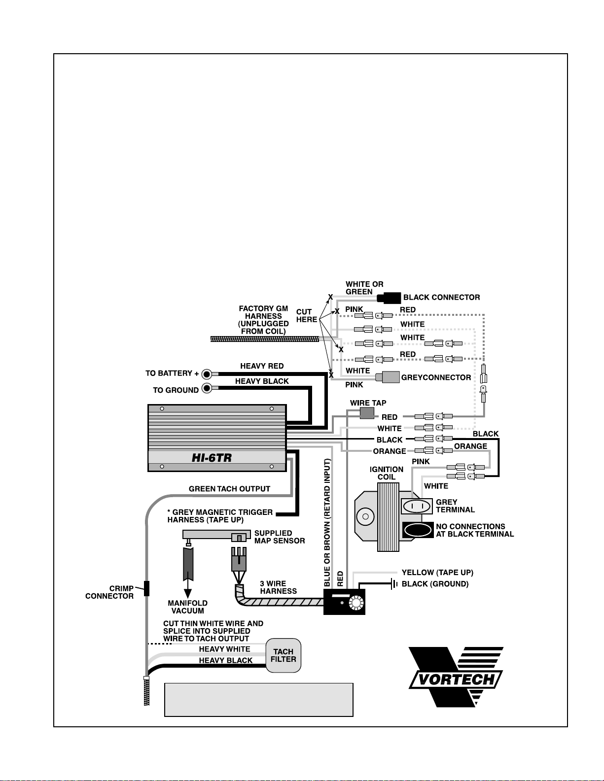
HARDWIRING INSTRUCTIONS FOR KITS NOT EQUIPPED
WITH A GM WIRING HARNESS
1. Unplug the grey and black connectors from the coil. Cut the
connectors off from the main harness approximately 2" from
the end.
2. Attach the supplied male and female connectors to lengthen the
white and pink wires previously cut from the coil connectors. Connect
the two pink wires together to one red wire and the two white wires
to the supplied single white wire. Attach the pink and white wires to
the red and white wires on the supplied ignition box.
3. Reattach the grey connector to the coil (leave the black connector
disconnected). Using the supplied male and female connectors,
attach the pink wire on the grey connector to the orange wire on
the supplied ignition box and attach the white wire to the black
wire on the ignition box.
VORTECH
®
CAPACITIVE DISCHARGE IGNITION
WITH AUTO-SEQUENCE REV LIMITER
*NOTE: CABLE CONTAINS RED AND BLACK LEADS.
MAKE SURE LEADS DO NOT CONTACT EACH
OTHER AND SHORT UNIT WHEN TAPING UP.
RANE
E
ELECTRONICS
R
C
HI-6TR
TIMING RETARD CONTROL
A
R
T
D
®
ENGINEERING, INC.
© 1995 VORTECH® ENGINEERING, INC. all rights reserved
Page 8
1994-1996 CORVETTE LTI SUPPLEMENT
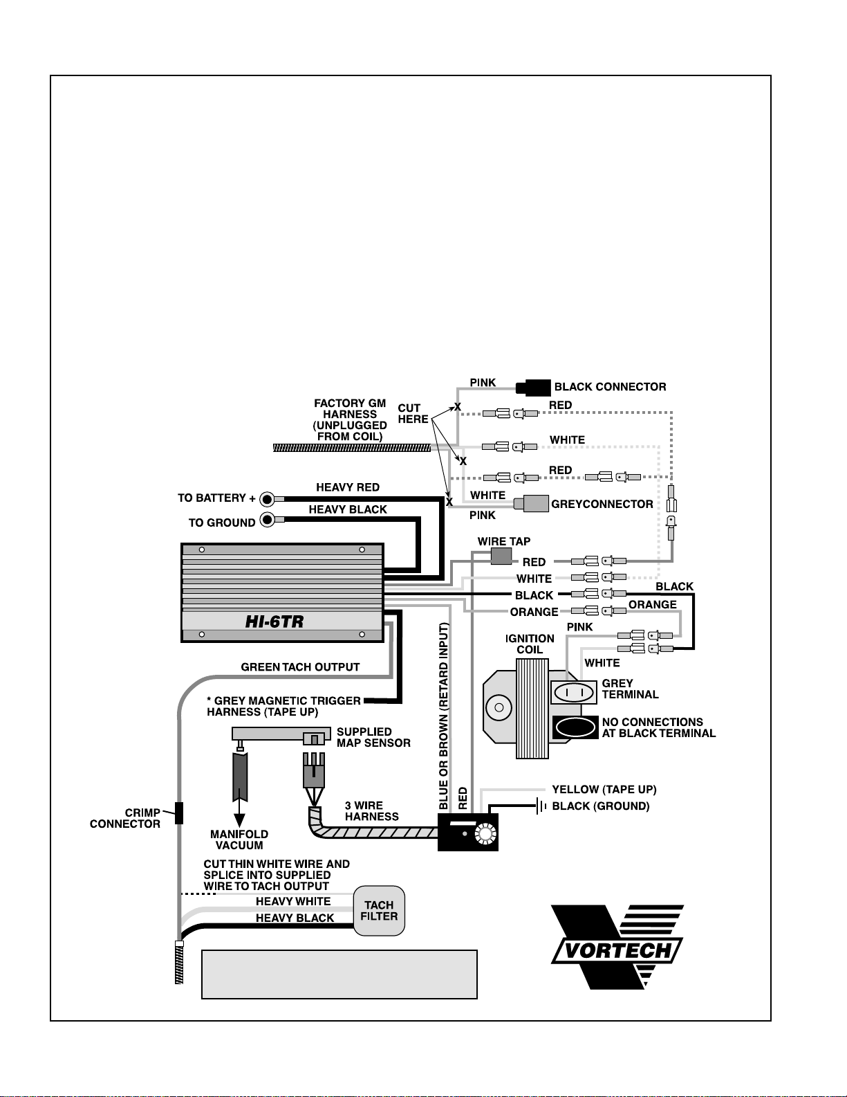
HARDWIRING INSTRUCTIONS FOR KITS NOT EQUIPPED
WITH A GM WIRING HARNESS
1. Unplug the grey and black connectors from the coil. Cut the con-
nectors off from the main harness approximately 2" from the end.
2. Attach the supplied male and female connectors to lengthen the
white and pink wires previously cut from the coil connectors. Connect the two pink wires together to one red wire. Attach the pink
and white wires to the red and white wires on the supplied ignition box.
3. Reattach the grey connector to the coil (leave the black connector disconnected). Using the supplied male and female connectors, attach the pink wire on the grey connector to the orange
wire on the supplied ignition box and attach the white wire to the
black wire on the ignition box.
VORTECH
®
CAPACITIVE DISCHARGE IGNITION
WITH AUTO-SEQUENCE REV LIMITER
*NOTE: CABLE CONTAINS RED AND BLACK LEADS.
MAKE SURE LEADS DO NOT CONTACT EACH
OTHER AND SHORT UNIT WHEN TAPING UP.
RANE
T
E
ELECTRONICS
R
C
HI-6TR
TIMING RETARD CONTROL
A
R
D
®
ENGINEERING, INC.
© 1994 VORTECH® ENGINEERING, INC. all rights reserved
Page 9
1992-1993 Corvette LT1
®
ENGINEERING, INC.
IMPORTANT: Before beginning installation, verify that all parts are included in the kit. Report any shortages or damaged parts immediately.
Part Number Description Quantity
2A229-018 SUPERCHARGER ASSEMBLY 1
2A129-028 V-1S supercharger 1
2A036-312 Supercharger 3.125" drive pulley 1
8R101-001 6 rib pulley retainer assembly 1
4GV111-021 MOUNTING BRACKET ASSEMBLY 1
4GV011-021 Mounting bracket 1
4GV010-034 Mounting plate 1
4GV010-010 Attachment plate 1
4GV010-040 Coil mount bracket 1
4GV017-011 Idler spacer 1
4GV017-021 Coil mount spacer 1
4FA016-170 Wide idler pulley 1
7A375-075 3/8-16 x 3/4" bolts 8
7A375-100 3/8-16 x 1" bolts 2
7A375-425 3/8-16 x 4-1/4" bolt 1
7A375-525 3/8-16 x 5-1/4" bolt 1
7J375-044 3/8" SAE washers 7
7F375-016 3/8-16 nuts 2
7K375-040 3/8" AN960 washers 7
7A375-375 3/8-16 x 3-3/4" bolt 1
7U125-000 6" heat sleeves 3
7P375-050 3/8" hosemender 1
7U030-056 3/8" x 7-1/4" hose 1
7U030-000 5/8" x 10" hose 1
7R001-004 #4 hose clamps 2
7R001-008 #8 hose clamps 2
7U100-055 6" nylon tie wraps 6
7A250-100 1/4-20 x 1" flat head screw 1
7F250-021 1/4-20 nut 1
7A375-224 3/8-16 x 2-1/4" bolts 3
4GV101-004 A/C LINE ASSEMBLY 1
4GV010-060 A/C drier bracket 1
7R005-003 200-87 T-bolt clamp 1
4GV014-040 A/C lines with ends 1
7E010-050 #12 x 1/2" sheet metal screw 1
4GV101-002 FUEL PUMP ASSEMBLY 1
4GV010-050 Pump mounting bracket 1
8F101-300 Pump wiring assembly 1
7R001-004 #4 hose clamps 2
7U100-055 6" nylon tie wraps 10
8F060-024 Fuel injectors 8
7R004-002 17.0 stepless clamps 2
7P375-050 3/8" hosemender 1
7C060-025 M6 x 1.00 x 25mm bolts 2
7C011-075 10/32" x 3/4" bolt 1
7F010-032 10-32 nylock nut 1
7J010-001 #10 flat washers 2
7C008-032 8-32 x 3/4" bolts 4
7F008-032 8-32 nylock nuts 4
7J008-001 #8 flat washers 8
5W001-014 Fuse holder 1
5W001-015 Blade type 20A fuse 1
5W001-012 Solderless connector 1
5W001-001 Wire tap 1
7J006-093 6mm washer 1
5W001-017 Large ring terminal 1
7U032-016 3/8" x 28" fuel hoses 2
8F001-200 200 inline fuel pump 1
7R004-001 15.7 stepless clamp 1
4GV114-020 WATER LINE ASSEMBLY 1
4GV055-010 Water tank 1
4GV014-010 Water pipe, L bend 1
4GV014-020 Water pipe, S bend 1
4GV014-030 Water pipe, Z bend 1
4GV014-051 Radiator pipe, polished 1
7R002-024 #24 hose clamps 2
7C010-050 10-24 x 1/2" socket heads 2
7R003-022 1-3/8" adel clamps 2
7R001-008 #8 stainless hose clamps 8
7J010-001 #10 flat washers 2
7P250-074 1/4-20 x 3/4" HXHD cap screw 1
7F250-021 1/4-20 nylock nut 1
7J250-001 1/4 SAE washer 2
4GV130-036 OIL DRAIN ASSEMBLY 1
7U030-036 1/2" x 35" oil drain hose 1
7P375-033 3/8" NPT x 3/8" NPT street elbow 1
7P375-017 3/8" NPT x 1/2" straight hose barb 1
7R001-008 #8 hose clamps 2
7U100-055 6" nylon tie wraps 4
7U100-066 11" tie wraps 4
Part Number Description Quantity
4GV112-010 AIR INTAKE ASSEMBLY 1
8H040-030 Air filter 1
4GV012-031 Air filter mount tube 1
7S300-000 3" 90° rubber elbow 1
7R005-002 200-84 T-bone clamps 2
4GV012-011 Air inlet tube 1
7R005-001 208-91 T-bone clamp 1
7U100-055 6" nylon tie wraps 3
7U375-052 3/8" vacuum cap 1
7U033-000 5/8" x 50" PVC hose 1
4GV012-041 Mass air tube 1
4GV011-034 Air filter tube bracket 1
7R001-008 #8 hose clamp 1
7R002-040 #40 hose clamp 1
7S350-200 3-1/2" x 2" sleeve 1
7R002-056 #56 hose clamps 2
7P750-100 3/4 NPT x 1" hose fitting 1
4GV112-020 AIR DISCHARGE ASSEMBLY 1
4GV012-028 Discharge tube, polished 1
7S400-200 4" x 2" sleeve 1
7R002-044 #44 hose clamps 2
8D001-002 Bypass valve 1
7S275-200 2-3/4" x 2" sleeve 1
7U136-020 7/8" x 20" heater hose 1
7R002-016 #16 hose clamps 2
7U030-046 5/32" x 46" vacuum line 1
7U030-046 5/32" x 1.5" vacuum line 1
7P156-082 5/32" tee 1
7R002-064 #64 hose clamps 2
4GV238-068 FUEL MANAGEMENT UNIT (w/lines) 1
6Z110-119 Fuel management unit, 10:1 1
4GV145-156 29" male fuel line assembly 1
4GV146-166 45" female fuel line assembly 1
7U030-046 5/32" x 36" vacuum line 1
7P156-082 5/32" tee 1
7J010-001 #10 flat washer 1
7U100-055 6" nylon tie wraps 6
5A101-007 HI-6TR ASSEMBLY 1
5A001-009 Crane HI-6TR ignition system 1
5A002-001 GM wiring harness 1
5W001-001 Wire tap 1
5W001-009 16-14GA male slides 11
5W001-010 16-14GA female slides 15
5W001-011 16-14GA eyelets 2
5W001-012 22-GA red solderless connectors 6
5W001-014 Fuse holder 1
5W001-015 20A blade type fuse 1
5W001-017 Large ring terminals 2
5W001-019 12-10GA solderless connectors 4
5W001-020 3/4" x 35" plastic wire loom 1
5W012-000 72" 12GA red wire 1
5W012-010 24" 12GA black wire 1
5W018-010 18" 18GA red wire 1
5W018-020 18" 18GA black wire 1
5W018-060 18" 18GA orange wire 1
5W018-070 50" 18GA green wire 1
5W018-240 18" 18GA white/yellow wire 1
5W022-060 78" 22GA blue wire 1
7E010-046 #8 x 3/4" sheet metal screws 2
7P156-082 5/32" tee 1
7U030-046 5/32" x 60" vacuum line 1
7U100-055 6" nylon tie wraps 6
7U375-001 9" Velcro® hook 1
7U375-002 9" Velcro® latch 1
5A002-006 Map sensor 1
4GV130-026 OIL FEED ASSEMBLY 1
7P125-034 1/8" NPT x 1/8" NPT street tee 1
7P125-027 1/8" NPT straight fitting 1
7P125-026 90° 1/8" NPT x #4 flare fitting 1
7P525-067 .500 crimp ferrules 2
7U030-016 1/4" x 54" fuel hose 1
7U100-055 6" nylon tie wraps 4
7P250-066 #4 swivel x 1/4" hose barb 2
4GV11 1-042 BELT TENSIONER ASSEMBLY 1
4GV011-032 Belt tensioner 1
4GV016-150 Idler-ribbed pulley 1
7GL10-150 10mm x 1.5" nylock nut 1
4GV116-021 DAMPENER PULLEY ASSEMBLY 1
4GV016-021 Harmonic balancer 1
2A046-510 Goodyear belt 1
7A437-176 7/16-14 x 1.75 belts 3
Part No. 4GV218-078S
PARTS LIST
Page 10
1994-1996 Corvette LT1
®
ENGINEERING, INC.
IMPORTANT: Before beginning installation, verify that all parts are included in the kit. Report any shortages or damaged parts immediately.
Part Number Description Quantity
2A229-018 SUPERCHARGER ASSEMBLY 1
2A129-028 V-1S supercharger 1
2A036-312 Supercharger 3.125" drive pulley 1
8R101-001 6 rib pulley retainer assembly 1
4GV111-021 MOUNTING BRACKET ASSEMBLY 1
4FA016-170 Wide idler pulley 1
4GV010-010 Attachment plate 1
4GV010-034 Mounting plate 1
4GV010-040 Coil mount bracket 1
4GV011-021 Mounting bracket 1
4GV017-011 Idler spacer 1
4GV017-021 Coil mount spacer 1
7A375-075 3/8-16 x 3/4" bolts 8
7A375-100 3/8-16 x 1" bolts 2
7A375-425 3/8-16 x 4-1/4" bolt 1
7A375-525 3/8-16 x 5-1/4" bolt 1
7J375-044 3/8" SAE washers 7
7F375-016 3/8-16 nuts 2
7K375-040 3/8" AN960 washers 7
7A375-375 3/8-16 x 3-3/4" bolt 1
7U125-000 6" heat sleeves 3
7P375-050 3/8" hosemender 1
7U030-056 3/8" x 7-1/4" hose 1
7U030-000 5/8" x 10" hose 1
7R001-004 #4 hose clamps 2
7R001-008 #8 hose clamps 2
7U100-055 6" nylon tie wraps 6
7A250-100 1/4-20 x 1" flat head screw 1
7F250-021 1/4-20 nut 1
7A375-224 3/8-16 x 2-1/4" stainless bolts 3
4GV11 1-042 BELT TENSIONER ASSEMBLY 1
4GV011-032 Belt tensioner 1
4GV016-150 Idler-ribbed pulley 1
7GL10-150 10mm x 1.5" nylock nut 1
4GV114-020 WATER LINE ASSEMBLY 1
4GV055-010 Water tank 1
4GV014-010 Water pipe, L bend 1
4GV014-020 Water pipe, S bend 1
4GV014-030 Water pipe, Z bend 1
4GV014-051 Radiator pipe, polished 1
7R002-024 #24 hose clamps 2
7C010-050 10-24 x 1/2" socket heads 2
7R003-022 1-3/8" adel clamps 2
7R001-008 #8 stainless hose clamps 8
7J010-001 #10 flat washers 2
7P250-074 1/4-20 x 3/4" HXHD cap screw 1
7F250-021 1/4-20 nylock nut 1
7J250-001 1/4 SAE washer 1
4GV112-030 AIR INTAKE ASSEMBLY 1
4GV011-034 Air filter tube bracket 1
4GV012-011 Air inlet tube 1
4GV012-031 Air filter mount tube 1
5W001-012 22 GA solderless connectors 6
5W001-067 3/16" x 6" shrink tube 1
5W011-010 3/8" x 36" flex loom 1
5W118-035 36" 18GA standard red wire 1
5W118-037 36" 18GA standard black wire 1
5W118-038 36" 18GA standard yellow wire 1
7P750-100 3/4 NPT x 1" straight hose fitting 1
7R001-008 #8 hose clamp 1
7R002-040 #40 hose clamp 1
7R002-056 #56 hose clamps 2
7R005-001 208-91 3.75" T-bone clamp 1
7R005-002 200-84 T-bone clamps 2
7S300-000 3" 90° rubber elbow 1
7S350-200 3-1/2" x 2" sleeve 1
7U100-055 6" nylon tie wraps 3
7U033-000 5/8" x 50" PVC hose 1
7U375-052 3/8" vacuum cap 1
8H040-022 3/4" breather 1
8H040-030 Air filter 1
4GV238-068 FUEL MANAGEMENT UNIT (w/lines) 1
6Z110-119 Fuel management unit, 10:1 1
4GV145-156 29" male fuel line assembly 1
4GV146-166 45" female fuel line assembly 1
7U030-046 5/32" x 36" vacuum line 1
7P156-082 5/32" tee 1
7J010-001 #10 flat washer 1
7U100-055 6" nylon tie wraps 6
4GV101-006 A/C LINE ASSEMBLY 1
4GV010-060 A/C drier bracket 1
4GV114-045 A/C line, with ends 1
7E010-050 #12 x 1/2" sheet metal screw 1
7R005-003 200-87 T-bolt clamp 1
Part Number Description Quantity
4GV112-020 AIR DISCHARGE ASSEMBLY 1
4GV012-020 Discharge tube, polished 1
7S400-200 4" x 2" sleeve 1
7R002-044 #44 hose clamps 2
8D001-002 Bypass valve 1
7S275-200 2-3/4" x 2" sleeve 1
7U136-020 7/8" x 20" heater hose 1
7R002-016 #16 hose clamps 2
7U030-046 5/32" x 46" vacuum line 1
7U030-046 5/32" x 1.5" vacuum line 1
7P156-082 5/32" tee 1
7R002-064 #64 hose clamps 2
4GV116-021 DAMPENER PULLEY ASSEMBLY 1
4GV016-021 Harmonic balancer 1
2A047-510 Goodyear belt 1
7A437-176 7/16-14 x 1.75 belts 3
4GV130-026 OIL FEED ASSEMBLY 1
7P125-034 1/8" NPT x 1/8" NPT street tee 1
7P125-027 1/8" NPT straight fitting 1
7P125-026 90° 1/8" NPT x #4 flare fitting 1
7P525-067 .500 crimp ferrules 2
7U030-016 1/4" x 54" fuel hose 1
7U100-055 6" nylon tie wraps 4
7P250-066 #4 swivel x 1/4" hose barb 2
4GV101-005 FUEL PUMP ASSEMBLY 1
4GV010-070 Fuel pump bracket 1
5W001-001 Wire tap 1
5W001-012 Solderless connector 1
5W001-014 Fuse holder 1
5W001-015 Blade type 20A fuse 1
5W001-017 Large ring terminal 1
7C008-032 8-32 x 3/4" bolts 4
7C011-075 10/32" x 3/4" bolts 2
7F008-032 8-32 nylock nuts 4
7F010-032 10-32 nylock nuts 2
7J006-093 6mm washer 1
7J008-001 #8 flat washers 8
7J010-001 #10 flat washers 4
7P375-050 3/8" hosemender 1
7R001-004 #4 hose clamps 2
7R004-002 17.0 stepless clamps 3
7U100-055 6" nylon tie wraps 10
7U032-016 3/8" x 28" fuel hoses 2
8F001-200 200 inline fuel pump 1
8F101-300 Pump wiring assembly 1
5A101-007 HI-6TR ASSEMBL Y 1
5A001-009 Crane HI-6TR ignition system 1
5A002-001 GM wiring harness 1
5W001-001 Wire tap 1
5W001-009 16-14GA male slides 11
5W001-010 16-14GA female slides 15
5W001-011 16-14GA eyelets 2
5W001-012 22-GA red solderless connectors 6
5W001-014 Fuse holder 1
5W001-015 20A blade type fuse 1
5W001-017 Large ring terminals 2
5W001-019 12-10GA solderless connectors 4
5W001-020 3/4" x 35" plastic wire loom 1
5W012-000 72" 12GA red wire 1
5W012-010 24" 12GA black wire 1
5W018-010 18" 18GA red wire 1
5W018-020 18" 18GA black wire 1
5W018-060 18" 18GA orange wire 1
5W018-070 50" 18GA green wire 1
5W018-240 18" 18GA white/yellow wire 1
5W022-060 78" 22GA blue wire 1
7E010-046 #8 x 3/4" sheet metal screws 2
7P156-082 5/32" tee 1
7U030-046 5/32" x 60" vacuum line 1
7U100-055 6" nylon tie wraps 6
7U375-001 9" Velcro® hook 1
7U375-002 9" Velcro® latch 1
5A002-006 Map sensor 1
4GV130-036 OIL DRAIN ASSEMBLY 1
7U030-036 1/2" x 35" oil drain hose 1
7P375-033 3/8" NPT x 3/8" NPT street elbow 1
7P375-017 3/8" NPT x 1/2" straight hose barb 1
7R001-008 #8 hose clamps 2
7U100-055 6" nylon tie wraps 4
7U100-066 11" tie wraps 4
Part No. 4GV218-088S
PARTS LIST
Page 11

1. COMPONENT REMOVAL
A. It is necessary to remove the refrigerant from the air condi-
tioning system. This should be performed by a qualified
technician using a Refrigerant Recycling System.
Releasing refrigerant into the atmosphere is environmentally irresponsible and should be avoided.
B. Disconnect the battery (negative lead).
C. Remove the air inlet. Pull out the intake air temperature
(IAT) sensor but leave it connected to the harness. Remove
the bellows, air filter cover and the entire assembly forward
of the throttle body. (If the vehicle is a 1994 model or later,
the mass air meter must be removed and set aside by
unplugging the wiring connection and cutting the clamps
fastening it to intake bellows).
D. Remove the radiator overflow tank underneath the right
(passenger) side headlight.
E. Remove the accessory drive belt and harmonic balancer.
(Do not remove the hub from the crankshaft.)
F. Drain coolant from the radiator. The drain fitting is located on
the bottom of the right tank.
G. Remove the radiator hose from the right side.
H. Remove the power steering reservoir and its related brack-
ets and hardware. Use a small container to catch the fluid
when the hoses are removed.
I. Remove the ignition coil and all of its mounting hardware on
the right side.
J. Number and remove the spark plug wires from the right
bank of the distributor. Place the wires out of the way.
K. Remove the right side injector cover.
1
Page 12

2. POWER STEERING LINE MODIFICATION
A. Remove the rubber hose and the two
fasteners from the 5/8" steel power steering
reservoir return line located on the front of
the engine. It is not necessary to remove the
line from the pump.
B. Use the tubing cutter to cut the steel reservoir
line 1-1/2" from the lower tab as shown in
the graphic and photo.
C. Use the 3/8" hose splice fitting, #4 clamps
and the section of 3/8" x 7-1/4" rubber hose
to extend the small rubber reservoir line.
Extend the 5/8" steel line with the 5/8" x 10"
rubber hose and the #8 clamps provided.
D. Reattach the 5/8" steel line to the engine
block using the tab and original fastener.
E. Slide a 6" section of heat protectant sleeve
over the end of each of the rubber power
steering lines. The lines should be positioned
as low and tight to the block as possible to
make room for the mounting bracket. The
3/8" rubber line, which runs back over the
crossmember, should be held tightly to the
frame horizontally and brought up next to
the 5/8" line. Refer to the photo. (Use tie
wraps to hold it to the frame and parallel to
the 5/8" reservoir line.)
F. Slide the third heat sleeve over all four (4) of
the spark plug wires located to the right and
reconnect them to the distributor.
TO RESERVOIR
DISCARD
THIS END
5/8" POWER STEERING
STEEL RESERVOIR
RETURN LINE
TO PUMP
1-1/2"
HEAT
PROTECTANT
SLEEVE
5/8" x 10" RUBBER HOSE
3/8" x 7-1/4" RUBBER HOSE
HEAT SLEEVES
•
•
•
3/8" ORIGINAL HOSE
CONNECTED TO POWER
STEERING RESERVOIR
2
Page 13

3. HARMONIC BALANCER
A. Be sure that both of the mating surfaces of the crank and
balancer are clean and free from rust and dirt.
B. Slide the new harmonic balancer onto the crankshaft hub.
C. Rotate the balancer on the crankshaft to find the proper bolt
hole alignment. Use the supplied 7/16" x 1-3/4" bolts with
Loctite® and start all three bolts; then torque to 60 ft./lbs.
4. OIL FEED LINE
A. The supercharger uses engine oil for lubrication and must
have an oil feed line connected to a filtered oil access on the
engine and an oil return. The return is a gravity drain and
must have a gradual drop connecting to the oil pan and
away from suspension components or exhaust pipes.
WARNING: The oil system contains a small
orifice that is easily plugged. DO NOT use
any type sealant on any of the threads.
Instead, use clean engine oil. Disassemble
and blow out entire line if you have any
doubts.
B. Remove the factory oil pressure sending unit located at the
rear of the intake manifold with a 1-3/16" crow's foot tool
(1994-1995 models need a 1-1/16" crow's foot tool).
C. Install the supplied 1/8" NPT street tee pointing to the right
side of the vehicle. (Refer to the graphic at right.)
D. Install the oil sending unit into the top of the tee.
E. Install the straight #4 flare into the remaining branch in the
tee, pointing toward the right side.
F. Install the black oil feed line onto the #4 flare. Cover the end
of the oil feed line to protect it from dirt and place it on top of
the manifold for later connection.
5. OIL DRAIN FITTING
5TH BOLT FROM
A. To provide an oil drain for the super-
THE FRONT
charger, it is necessary to make a hole in
the oil pan. It is best to punch the pan
rather than drill. Remove paint around
2-3/4"
the hole area so that it does not flake into
the pan.
B. Make a mark on the driver's side of the oil
pan ahead of the oil filter. The mark must
be 2-3/4" below the oil pan mounting flange
and rearward of the fifth bolt (from the
front) 3/4".
1/8" NPT
STREET
TEE
ENGINE BLOCK
OIL
SENDING
UNIT
#4 FLARE
PASSENGER
SIDE
3/4"
3
Page 14

5. OIL DRAIN FITTING, cont'd.
C. Use a small center punch to perforate the pan
and expand hole. Switch to a larger diameter
punch and expand the hole further to approximately 9/16" diameter. Most punches are made
from hexagon material and may be placed in a
socket with an extension to make this procedure
easier.
CAUTION: Use care so as not to strike
internal engine components when punching oil pan.
D. Tap the hole with a 3/8" NPT tap approximately
1/4" deep. Pack the flutes of the tap with heavy
grease to hold chips. Use a small magnet to
check for any stray chips.
NOTE: This method of rolling over the lip
of the hole and tapping it works very well
if carefully done and should cause no
problems.
E. Thoroughly clean the threaded area. Apply a
small amount of silicone sealer to the new
threads. Apply more sealer to the 3/8" NPT
street elbow and secure in hole (elbow must
point toward the front of the vehicle). Make sure
a seal is formed all around the fitting. Thread the
3/8" NPT x 1/2" barb fitting into the fitting
installed in the pan using pipe sealer.
F. Change the engine oil and filter.
6. FUEL MANAGEMENT UNIT INSTALLATION
A. Attach the Fuel Management Unit (FMU) to the
FMU bracket with the flare fittings pointing
down and toward the front of the vehicle as shown
in the graphic.
B. Install the FMU and bracket assembly in the space
between the heater blower and coolant surge
tank. Sandwich one end of the bracket between
the blower motor and the relay bracket. Use the #8
washer as a spacer in the rear relay hole. Secure
the inboard end at the surge tank bracket. Use the
original bolts. (Refer to the photos on next page.)
CONNECT TO MANIFOLD
VACUUM/PRESSURE
OUTLET (FUEL
FROM HERE
RETURNS TO TANK)
FMU BRACKET
INLET (FUEL LINE
FROM STOCK
REGULATOR)
4
Page 15

6. FUEL MANAGEMENT UNIT INSTALLATION, cont'd.
C. Using a spring-lock fitting disconnect tool,
disconnect the return line (the line closest
to the front of the car) from the fuel rail (at
the top rear of the intake manifold).
D. Install the supplied 45" fuel line by
connecting the female spring-lock end
onto the fuel rail. Run the line parallel to
the feed line and then downward behind
the wheel well to the FMU. The flare end
will be connected to the 90° inlet fitting on
the FMU.
E. Fit the 28" male fuel line into the braided
tank return line. Route the braided tank
return line assembly forward to form a
smooth radius pointing downward. Use
tie wraps to hold the line in position.
Route the flared end of the line downward
behind the wheel well with the other FMU
line to the FMU. Connect the line to the
•
center fitting.
TO FMU
OUTLET
NOTE: Make sure you have routed
all fuel lines away from all moving
parts, sharp edges, exhaust pipes
and manifold. Secure the fuel lines
with the tie wraps.
MANAGEMENT
FUEL
UNIT (FMU)
FUEL
RETURN
LINE
STANDARD
PUMP
TO MANIFOLD PRESSURE
FUEL
FEED
LINE
ADDITIONAL
FUEL PUMP
FUEL
TANK
•
TO FMU
INLET
ENGINE
5
Page 16

7. COOLANT LINE MODIFICATIONS
A. Radiator hose
1) Modify the previously removed radiator
hose as shown in the graphic at right. Cut
a 2" piece from the upper end for the
thermostat housing.
2) Remove a 1-1/2" section where the hose
attaches to the radiator and discard.
Reconnect the modified hose.
3) Cut and discard the portion of the bottom
section as shown in the graphic.
B. Surge tank hose
NOTE: On 1992 LT1 models the
coolant hoses are slightly
different. Remove the upper
coolant lines and modify
according to the diagram on page
7. The throttle body coolant hose
must be routed near the valve
cover using the "Z" bend 3/4"
diameter tube. Disregard points 1
and 2 in section B.
DISCARD
SAVE THIS
PORTION
SAVE FOR
2"
THERMOSTAT
HOUSING
CUT AT END OF
STRAIGHT PORTION
1-1/2"
RADIATOR
DISCARD
•
1) Cut the hoses at the left and right sides of
the plastic tee in the surge hose (refer to
the graphic on page 7, 1993-1994 models;
1995-1996 models do not have a tee
located in the surge tank hose line).
2) Discard the short portions and reconnect
the modified hoses to the plastic tee with
the original clamps.
3) Cut a 2" section off the end that connects
to the water pump and reconnect one of
the ends with the OEM clamp.
4) Cut off the remaining portion as shown in
the graphic on page 8 and install the "S"
shaped aluminum tube with the short end
into the 2" hose on the water pump.
'S' BEND
ALUMINUM TUBE
•
'L' BEND
ALUMINUM TUBE
(HEATER CORE HOSE)
6
Page 17

C. HEATER CORE HOSE
NOTE: For 1992 LT1 models, disregard the
following five points. There are no lower
water pump hoses to modify.
1) Remove the heater core hose from the water pump
(refer to the graphic on page 7). Cut off the last 4" of hose
at the water pump end. Set aside for now.
2) Cut off 2-1/2" of hose at the restrictor end.
3) Assemble the short end of the "Z" shaped aluminum
tube into the 2-1/2" hose on the restrictor with a #8
clamp.
4) Slide the 4" connector piece that was previously set
aside and the #8 clamps onto the long end of the
remaining single "L" curve aluminum tube. Slide the "L"
bend assembly onto the "Z" bend. Connect the hoses as
shown in the graphic on the next page.
5) Using the rubber "S" shaped coolant hose cut from the
original heater core hose and #8 clamps, connect the
single "L" curved aluminum tube to the water pump.
1992 MODELS ONLY
"Z" BEND
ALUMINUM TUBE
THROTTLE
BODY HOSE
SURGE TANK
OUTLET HOSE
VALVE COVER
DISCARD
2"
2"
"S" BEND
ALUMINUM
TUBE HERE
7
Page 18

1993-1996 MODELS ONLY
TO
WATER
PUMP
2"
USE "S" BEND
ALUMINUM
TUBE HERE
RADIATOR SURGE TANK HOSE
NOTE: 1995 MODELS DO NOT
HAVE A THROTTLE BODY
HOSE AND PLASTIC TEE. DO
NOT CUT MAIN COOLANT
HOSE.
USE
THIS
PORTION
1-3/4"
HEATER CORE HOSE
RESTRICTOR
2-1/2"
TO THRO TTLE BODY
CUT AND
DISCARD
TOP VIEW
DISCARD
THIS PORTION
1-1/4"
DISCARD
THIS PORTION
CUT A T END
OF STRAIGHT
PORTION
USE
THIS
PORTION
LOWER
WATER
PUMP
4"
(USE FOR
CONNECTOR)
UP
"Z" BEND
ALUMINUM
TUBE
NOTE: THE "Z/L"BEND WATER
TUBE ASSEMBLY NEEDS TO
BE ROUTED DOWN ON TOP OF
THE VEHICLE FRAME AND
UNDER THE PIVOT OF THE
RIGHT SIDE CONTROL ARM.
4"
CONNECTOR
8
USE
THIS
PORTION
CUT A T END
OF STRAIGHT
PORTION
"L" BEND
ALUMINUM
TUBE
Page 19

8A. AIR INLET (1992-1993 Models)
A. Trim the fiberglass splash guard as shown in the
graphic.
B. Install the air filter mounting tube and bracket into
the right side front headlight well (ahead of the
wheel) where the coolant reservoir was originally
located. Use the original holes and bolts to secure
the bracket.
C. Install the rubber 90° elbow with a #200-84 band
clamp onto the air inlet on the engine compartment
side.
D. Use a #40 clamp to attach the filter tube to the
mounting bracket. Install the 3-1/2" sleeve and
#56 clamps, attaching one of the clamps to the
bracket as shown.
E. Install the air filter extension and clamp onto the air
inlet tube inside of the right side headlight pocket
(1992-1993 models only). Attach air filter.
8B. AIR INLET (1994-1996 Models)
A. Follow steps 8A-D above.
B. Locate the MAF sensor connector in the vehicle
wiring harness and cut all three wires approximately 2" away from the connector.
C. Extend the MAF connector by using the supplied
36" wires and shrink sleeve. Soldering is recommended. Crimp connectors have been supplied
for applications where soldering is not possible.
VIEW FROM
BOTTOM
RIGHT
FRONT
TIRE
FRONT
NOTE: Double check the wire to wire (MAF
and harness) relationship before soldering
and sealing.
D. Attach the MAF meter to the air filter tube as
shown. Route the MAF connector down into the
headlight well and attach to the air meter. 3/8" flex
loom has been provided to protect the extended
harness. Attach the supplied air filter to the air
meter inlet.
1992-1993
AIR FILTER
TUBE BRACKET
#40 CLAMP
#56 CLAMPS
AIR FILTER
EXTENSION
3-1/2" X 2" SLEEVE
1994-1995
OR
_
MAF METER
TOP VIEW
AIR FILTER TUBE
RUBBER ELBOW
AIR INLET DUCT
HEADLIGHT
WELL
BRACKET
RIGHT
FRONT
TIRE
9
Page 20

9. COOLANT RECOVERY TANK
A. Install the supplied coolant reservoir into the right side
front headlight well (next to the air inlet). Use the
existing hole and supplied fasteners to attach the
reservoir to the fender well (see photo).
B. Carefully bend the original overflow line around the
fender well and connect to the new reservoir.
C. Attach the 5/32" vent line to the top fitting on the
reservoir and route out of the engine compartment.
AIR FILTER
RECOVERY TANK
COOLANT
10. AIR CONDITIONING ACCUMULATOR RELOCATION
A. Remove the air conditioning line from
the accumulator to the evaporator (right
TOP VIEW
side).
B. Remove the air conditioning line clamp
and screw located on the frame
crossmember in front of the water pump
FRAME
near the accumulator.
C. Use the mounting hole and bolt to line
up the supplied "T" bracket (refer to the
graphic). Mount the adel clamp and air
conditioning line on top of the "T"
bracket. Drill a hole with a #12 drill in
the frame using the remaining hole in
the bracket for a template. Install the
EXISTING HOLE,
SCREW IN CLAMP
supplied #12 sheet metal screw.
D. Carefully bend the outermost line at the
air conditioning compressor outward
slightly to pull the accumulator into
position onto the bracket. Use a second
hand to support the line at the
compressor, being careful not to kink
the line (refer to the photo).
E. Position the accumulator onto the
bracket and secure with the band clamp
provided.
F. Install the supplied aluminum air
conditioning line making sure the
O-rings are in place at the ends of each
fitting.
CANISTER
•
CLAMP
AIR CONDITIONING LINE
DRILL HOLE #12
USE #12
SHEET METAL SCREW
FRONT
"T" BRACKET
ACCUMULATOR
10
Page 21

11. INTAKE AIR TEMPERATURE (IAT)
CUT
DRILL OUT
DIMPLE TOP .25"
COUNTERSINK
TO .40"
SENSOR THREADING
A. Disconnect the IAT sensor from the harness.
B. With a file, remove the ridges from the sensor and
thread the sensor to 1/2"-20 with a die.
C. Install the threaded sensor into the supercharger
discharge duct and secure.
12. MOUNTING BRACKET
A. Mount the spring tensioner to the mounting bracket with
the supplied hardware. Place the bolt through the center
hole in the bracket and position it so that the alignment
stud fits into the hole.
B. Fasten the mounting bracket to the engine block and
heads using three (3) 3/8-16 x 2-1/4" bolts, one (1)
3/8-16 x 4-1/4" bolt, and four (4) 3/8" flat washers. Make
sure that the power steering lines and plug wires are
safely secured behind the bracket and the three sections
of heat sleeve are positioned properly, staying clear of
the exhaust.
C. Modify the power steering bracket by cutting the existing
tab to mirror the opposite side of the bracket (refer to
graphic).
D. Attach the power steering reservoir to the appropriate
hoses with the supplied clamps.
E. Using the dimple as a location point, drill a .25" through
hole. Countersink to .40".
F. Attach the modified power steering reservoir bracket to
the backside of the mounting bracket with the 1/4-20 x
1" flat head screw, locking nut and flat washer. Refer to
graphic on following page for further reference.
REMOVE RIDGES
USE A 1/2"-20 DIE TO
THREAD THIS PORTION
11
Page 22

12. MOUNTING BRACKET
3/8-16 x 5-1/4"
1/4-20 x 1"
FLATHEAD
POWER
STEERING
RESERVOIR
MOUNT
SPRING
TENSIONER
MOUNTING
BOLT
SPRING
TENSIONER
ALIGNMENT
STUD
SPRING TENSIONER
ATTACHMENT
PLATE
3/8-16 x 2-1/4"
SMOOTH IDLER
PULLEY
3/8-16 x 3/4"
PULLEY
SPACER
TUBE SPACER
MOUNTS TO
SUPERCHARGER
3/8-16 x 2-1/4"
3/8-16 x 4-1/4"
3/8-16 x 2-1/4"
3/8-16 x 1"
3/8" AN WASHER
RIBBED TENSIONER
PULLEY
12
3/8-16 x 1"
3/8" AN WASHER
3/8-16 x 3-3/4"
3/8" AN WASHER
Page 23

13. SUPERCHARGER MOUNTING PLATE
A. Place the supercharger belt around the
crank pulley and under the spring
tensioner.
B. Make sure the belt routes around the large
riser on the mounting bracket (passenger
side, above the spring tensioner), as shown
in the graphic, BEFORE the mounting
plate is put into position.
C. Place the smooth idler pulley and spacer
onto the bracket (make sure that the belt
is routed underneath the idler pulley). Place
the plate into position with a 3/8-16 x 3-1/2"
bolt and 3/8" AN washer through the plate
to hold the pulley and spacer in position.
Fasten down the plate with the remaining
two (2) 3/8-16 x 1" bolts and 3/8" AN washers
to the bracket.
SUPERCHARGER
PULLEY
RISER
14. SUPERCHARGER INSTALLATION
A. Attach the air inlet duct to the supercharger inlet with the
#208-91 clamp. Position the inlet so that it points downward,
parallel to the drain fitting. Leave the clamp loose so that the
air inlet duct can be rotated for adjustment.
B. Attach the 36" drain hose and clamp to the fitting on then
bottom of the supercharger. Make sure that the clamp is
rotated so that it will not interfere with the mounting plate
when installed.
C. Slide a #200-84 clamp onto the 90° rubber inlet elbow.
D. Lower the supercharger/air inlet duct assembly down onto
the supercharger plate. Rotating the air inlet duct and
supercharger slightly to clear the radiator and mounting
plate bolts will ease installation. Feed the oil drain downward
and toward the left side.
E. Install the four (4) 3/8-16 x 3/4" bolts and 3/8" AN washers
into the supercharger through the bracket underneath,
using a 9/16" socket and 1/4" drive ratchet with swivel.
F. Use the 3/8-16 x 5-1/4" bolt, 3/8" washer, 4 hole attachment
plate (use the single hole in the middle with the upper single
hole offset toward the throttle body) and the tube spacer (in
the same order) to connect the upper portion of the
supercharger to the supercharger bracket.
13
Page 24

14. SUPERCHARGER INSTALLATION (cont'd.)
G. Mount the spacer/bolt assembly onto
the main mounting bracket with the
two (2) 3/8-16 x 3/4" bolts and washers.
Thread the 5-1/4" bolt into the
supercharger (refer to the photo).
H. Tighten the air filter mount to the 90°
elbow. Tighten the air inlet duct onto
the supercharger.
I. Mount the short end of the coil-mount
bracket to the throttle body (remove
the upper right bolt from the throttle
body) and the other end to the coil
(refer to the graphic). Mount the
opposite end of the coil to the
attachment plate. Fasten with the two
(2) 3/8-16 x 3/4" bolts, nuts and
washers.
J. Route the supercharger belt around
the crank pulley on the rear set of
grooves and underneath both the
spring tensioner and smooth idler
pulley. From the left side, place a
15mm box wrench on the spring
tensioner hex. Pull up to provide room
for the belt to slip onto the supercharger
pulley. Release tension and install the
accessory belt following the factory
procedure.
K. Install the 90° 1/8" NPT fitting into the
supercharger oil feed with the flare
pointing to the right side.
L. Fasten the oil feed line to the flare
fitting on the supercharger.
5-1/4-16 x 3/8" BOLT
WARNING: The oil system
contains a small orifice that is
easily plugged. DO NOT use
any type sealant on any of the
threads. Instead, use clean
TOP VIEW
PASSENGER SIDE
engine oil. Disassemble and
blow out entire line if you have
any doubts.
THROTTLE
BODY
3/8-16 x 3/4"
BOLT
4 HOLE
ATTACHMENT
PLATE
DISCHARGE
DUCT
COIL-MOUNT BRACKET
(SHORT STRAIGHT END)
3/8-16 x 3/4" BOLT
COIL
TUBE
SPACER
3/8-16 x 3/4" BOLT
SUPERCHARGER
FRONT
14
Page 25

15. DRAIN LINE
NOTE: It is important that the super-
charger oil drain line be routed
gradually downward without dips,
away from heat, sharp objects and
moving parts.
A. Route the supercharger drain hose downward
behind the front frame crossmember.
Using tie wraps, secure the drain hose to the
steel power steering pressure line located on
the steering rack. See fig. A.
B. Route the drain hose around the front of the
crank pulley to the driver's side of the engine.
Make sure that the hose maintains smooth
downhill routing.
C. Use tie wraps to secure the hose to the rear
power steering line, away from the crank
pulley and accessory belt. See fig. A and B.
D. Attach the end of the drain hose to the 1/2"
drain fitting barb in the oil pan and secure with
the supplied #8 hose clamp. Trim the hose
length if necessary.
FROM
SUPERCHARGER
FRAME
POWER STEERING RACK
ROUTE THE DRAIN HOSE AROUND THE CRANK
PULLEY AND BACK TO THE 1/2" BARB IN THE PAN
TIE WRAP
TO POWER
STEERING LINE
VIEW FROM FRONT
FIG. A
DAMPENER PULLEY
OIL DRAIN HOSE
FIG. B
CRANK
PULLEY
OIL PAN
OIL PAN
16. RADIATOR PIPE
A. Install the previously cut radiator hoses on the radiator and
water neck with OEM clamps.
B. Install the supplied stainless coolant pipe and #24 clamps.
C. Install the two adel clamps, #10-24 x 1/2" screws and #10
washers to hold the coolant pipe in place on top of the air
inlet duct.
17. DISCHARGE TUBE
A. Using the #44 clamps, place the 2-3/4" blue sleeve onto the
supercharger discharge. Place the large sleeve onto the
throttle body using #72 clamps.
B. Install the discharge tube and secure with the clamps to the
supercharger and throttle body.
C. Hook up the IAT sensor connector.
D. Connect the length of 7/8" hose from the bypass valve to the
barb on the air inlet duct with the #16 hose clamps. Trim the
hose, if necessary.
15
Page 26

18. VACUUM AND BREATHER LINES
A. Remove the fuel regulator vacuum connection from the
manifold. Place the 1-1/2" length of 5/32" tubing and a 5/32"
vacuum tee on the manifold vacuum spout. Connect the tee
to the original fuel regulator line and the 32" vacuum line to the
bypass valve.
B. Connect the 36" FMU vacuum line from the FMU to the
bypass vacuum line by using a 5/32" tee to splice the lines
together.
C. Remove the breather line that connects the throttle body to
the valve cover. Place a 1/2" vacuum cap on the nipple at the
throttle body. Take the plastic 90° breather line and cut as
shown in the graphic at right.
D. Install the supplied 5/8" breather line from the fitting on the air
filter tube to the 90° valve cover breather.
E. On 1994-1995 models, remove the 3/4" air pump inlet hose
and section out a straight 4" piece. Install the supplied
breather in one hose end and install the other end onto the
pump inlet.
NOTE: On some 1994/1995 models there is a 5/32"
vacuum line running from the spark distributor
module to the throttle body air inlet hose. Reroute
the end originally connected to the air inlet hose to
the new inlet duct located in between the MAF and
the supercharger.
6"
INTAKE
TO
REGULATOR
5/32" VACUUM LINE
VALVE COVER
FMU
THROTTLE
BODY
POWER
STEERING
RESERVOIR
BYPASS
VALVE
TO MSD
SUPERCHARGER
5/8" VALVE COVER
BREATHER LINE
AIR FILTER
16
Page 27

19. IGNITION/BOOST CONTROL INSTALLATION
A. Mount the Ignition/Boost Control unit above the
®
radiator shroud using Velcro
strips (see photo).
B. Route the heavy black cable to a clean ground.
Route the heavy red cable to the battery. Using
a solderless connector, connect the supplied
fuse holder and fuse to the end of the wire. Set
the wire aside for now (do not connect to the
battery).
D. Install the Ignition/Boost Control wiring harness
following the graphic on the next page. Use the
supplied wire and connectors to extend some of
the wires, if needed.
E. Locate the tachometer filter in the factory coil
harness. (Note: 1994 and 1995 models are not
equipped with tach filters. In this case, ignore
step "E".) Cut the thin white wire located near
the filter. Splice the supplied length of wire and
connectors into the thin white wire and run to
the green tach output wire on the Ignition/Boost
Control unit.
F. Mount the timing control knob in an easily
accessible position from the drivers seat. Attach
the black wire to a clean ground and the red wire
to a keyed on 12V power source or the red wire
from the Vortech ignition box. Tape up the end
of the yellow wire to prevent contact with a
metal surface. Route the three-wire harness
out into the engine compartment near the battery.
Connect the supplied GM-style map sensor to
the three-wire harness and secure.
G. Route a vacuum line from the supplied map
sensor to the bypass/vacuum line assembly
using a 5/32" tee.
17
Page 28

19. IGNITION/BOOST CONTROL INSTALLATION, cont'd.
FACTORY GM
HARNESS
(UNPLUGGED
FROM COIL)
GM ADAPTER
HARNESS
VORTECH
CRIMP
CONNECTOR
TO BATTERY +
TO GROUND
®
CAPACITIVE DISCHARGE IGNITION
WITH AUTO-SEQUENCE REV LIMITER
GREEN T ACH OUTPUT
GREY MAGNETIC TRIGGER
HARNESS (TAPE UP)
MANIFOLD
VACUUM
CUT THIN WHITE WIRE AND
SPLICE INTO SUPPLIED
WIRE TO T ACH OUTPUT
HEAVY WHITE
HEAVY BLACK
HEAVY RED
HEAVY BLACK
SUPPLIED
MAP SENSOR
3 WIRE
HARNESS
TACH
FILTER
BLUE (RETARD INPUT)
RED
RANE
E
ELECTRONICS
R
C
HI-6TR
TIMING RETARD CONTROL
IGNITION COIL
A
R
T
D
WIRE TAP
RED
WHITE
BLACK
ORANGE
NO CONNECTIONS
AT GREY TERMINAL
BLACK
TERMINAL
YELLOW (TAPE UP)
BLACK (GROUND)
18
Page 29

20. IGNITION/BOOST CONTROL OPERATION
A. The Ignition/Boost Control unit is
designed to retard ignition in relation
to boost.
B. The unit is adjustable from 0° of ignition
Example of Ignition Retard vs. Boost:
[5 psi at 3° per per lb.]
retard to 4° of ignition retard for
each pound of boost, up to a
maximum of 20°.
15
C. Using the 1° per pound position as a
starting point, adjust the ignition retard
knob until just beyond the point of
10
detonation. Use third gear for testing
in a safe area or road. Adjust the
retard according to changes in altitude
and fuel quality.
5
Degrees of Retard
[7 psi at 2° per per lb.]
Maximum Retard = 20°
Maximum Retard = 15°
[10 psi at 1/2° per per lb.]
Caution: It is extremely
important that the boost retard
5 7 10
psi Boost
never be turned to 0°. It is
recommended that in stock
street applications, the knob
be at no less than 1°/lb.
21. AUXILIARY FUEL PUMP INSTALLATION
A. Remove the license plate and frame, gas door, gas cap and
rubber fuel overflow catch.
B. Using a 3/4" socket, lower the spare tire and cover assembly.
C. Install the wiring harness/relay assembly into the spare tire
well area on the inside of the bumper (underneath the car).
Use one of the square holes in the seam of the fuel tank, a #10
screw and nylon locking nut to secure the relay assembly. On
some models, a hole for the relay mount may have to be
drilled. Make sure the relay is positioned well inside the spare
tire well to eliminate possible spare tire and fuel overflow
contact.
D. Secure the fuel pump/lines assembly onto the steel mounting
bracket with the provided clamps and #8 fasteners in the
direction shown in the graphic on page 21.
19
Page 30

21. AUXILIARY FUEL PUMP INSTALLATION, cont'd.
NOTE: On 1994-1996 Models disregard
step E. Install the fuel pump assembly
onto the vehicle through the license
plate opening. Use the supplied 1032 hardware to mount the pump
assembly to the existing hole in the
aluminum rear section. See photo.
E. Remove the 6mm bolt that holds the spare tire bracket in
position (threads from the front). Install the fuel pump
assembly onto the vehicle through the license plate opening.
Use the spare tire bracket hole and supplied 6mm x 25mm
bolt to line up the left side fuel pump bracket hole. Use the
corresponding hole in the fuel tank seam to mount the right
side pump bracket. Use the supplied 6mm screw, nylon
locking nuts and washers to secure (see photo).
F. Disconnect the factory fuel supply hose and connect the
new hoses as shown in the graphic on the next page. Use
the supplied tie wraps to keep the fuel lines away from sharp
objects. Make sure the lines are routed in such a way that
they make gradual turns with no sharp kinks or bends.
G. Wire the negative terminal on the pump and the #86 relay
terminal to a clean ground, free from rust and paint.
H. Using the yellow wire from the #85 relay and a wire tap,
splice into the grey wire in the factory fuel pump harness.
I. Connect the #87 red wire on the relay to the positive terminal
on the T-Rex® fuel pump.
J. Run the remaining long red wire up to the battery, using tie
wraps to keep the wire away from heat and moving parts.
Using a solderless connector, connect the supplied fuse
holder and fuse to the end of the wire. Using the large ring
terminal, crimp both the ignition/boost control fuse wire and
the fuel pump fuse wire together (in the same terminal).
Connect the ring terminal to the (+) positive battery post.
K. Replace the license plate and frame, gas door, fuel overflow
catch and gas cap.
L. Refer to the graphic on the next page to confirm that all wires
are routed correctly. Replace the spare tire and cover,
making sure that the wires and relay are not contact with the
spare tire and mounting fasteners.
20
Page 31

21. AUXILIARY FUEL PUMP INSTALLATION (cont'd.)
RELAY
(+) TERMINAL ON
86
87
87A
T-REX FUEL PUMP
85
GROUND
3/8" x 28"
30
1994-95 MODELS
(+) BATTERY
TERMINAL
GREY
PURPLE
BLACK
3/8" HOSE MENDER
3/8" x 28"
WIRE TAP
FUEL WIRING
CONNECTOR
RETURN
ORIGINAL TANK
OUTLET
+
-
M6 x 1.00 x 25 mm HEX HEAD
NOTE: 1994-95 MODELS
DO NOT HAVE A LEFT SIDE
MOUNTING PLATE HOLE
®
T-REX
FLOW
21
#8-32 x 3/4"
#8 LOCKNUT (4x)
#8 WASHERS (4x)
®
FUEL PUMP
MOUNTING PLATE
1992-93 MODELS
M6 x 1.00 x 25mm HEX HEAD
M6 LOCK NUT
M6 WASHERS (2)
OR
1994-95 MODELS
10-32 X 3/4" HEX HEAD
10-32 LOCK NUT
#10 WASHERS (2)
Page 32

22. FUEL INJECTOR REPLACEMENT
(1992-1993 Models only)
A. Remove the right side injector cover.
B. Disconnect the eight (8) fuel injector wiring connectors and
retainers from the injectors.
C. Remove the four (4) 10mm bolts holding down the fuel rail
on the intake manifold. Lift up on the rails evenly, removing
all eight (8) injectors.
D. Using a small amount of clean motor oil, lightly lubricate the
O-rings on both ends on the Vortech supplied fuel injectors.
E. Install the new injectors into the fuel rails with the terminals
facing outward. Attach the injector retainers into the top
injector groove.
F. Carefully lower the fuel/rail injector assembly down onto the
intake manifold. Check to see that each injector has been
seated properly into the manifold.
G. Tighten down the fuel rail assembly with the original bolts
and attach the wiring connectors to the injector terminals.
H. Replace the left and right side injector covers.
NOTE: Make sure injector retainers are
secure and properly installed. Recheck
after cycling fuel system.
23. FINAL ASSEMBLY AND CHECK
A. Make sure that the pan fitting is tight and the engine is filled
with factory specified synthetic oil.
B. Fill the coolant surge tank with a 50/50 coolant/water mix.
C. Fill the overflow tank approximately one quarter full.
D. Reconnect the battery.
E. If your vehicle has gone over 10,000 miles since its last
spark plug change, you will need to change the spark plugs
now before test-driving the vehicle.
F. Check all fittings, nuts, bolts and clamps for tightness. Pay
particular attention to oil and fuel lines around moving parts,
sharp edges and exhaust system parts. Make sure all wires
and lines are properly secured with clamps or tie wraps.
G. Check all fluid levels, making sure that your tank is filled with
92 octane or higher fuel before commencing test drive.
NOTE: Do not attempt to operate the air
conditioning until a qualified air
conditioning technician has performed the
necessary steps to purge and recharge
the air conditioning system.
22
Page 33

23. FINAL ASSEMBLY AND CHECK (cont'd.)
H. Start the engine and bleed the cooling
system at the water neck until a steady
stream of coolant comes out of the
fitting. Retighten the bleed screw.
I. Recheck to be sure that no hoses,
wires, etc. are near exhaust headers or
moving parts and for signs of any fluid
leakage. Check ignition timing to make
sure it is set to stock specifications
before commencing test drive.
J. Test drive the vehicle.
K. Recheck the coolant and oil level.
L. Read the STREET
SUPERCHARGER SYSTEM
OWNER'S MANUAL AND
WARRANTY REGISTRATION FORM
within thirty (30) days of purchasing
your supercharger system to qualify.
NOTE: Operating the vehicle without ALL
the subassemblies completely and
properly installed may cause FAILURE
OF MAJOR COMPONENTS.
WARNING: Do not attempt to operate the
vehicle until ALL components are
installed and ALL operations are
completed including final check.
®
ENGINEERING, INC.
© 1997 VORTECH® ENGINEERING, INC. all rights reserved
23
 Loading...