

Page 1

'92-'95 1.6L SOHC VTEC HONDA FUEL RAIL
INSTALLATION INSTRUCTIONS
Tools Required:
• Metric socket set and ratchet
• Extension (optional)
• 5/32", 1/4" Hex keys
• 3/4”, 10mm, 22mm Open end wrenches
• Pliers
• Torque wrench
• Blue Loctite 247
NOTE: Before beginning installation of the
Maxflow fuel rail, it is imperative to
ensure that the vehicle's engine is cool
to the touch, and that the fuel pressure
has been properly relieved.
1. Disconnect the negative (-) battery cable from the battery
negative terminal.
WARNING: Do not smoke while working on
fuel system. Keep open flame
away from your work area!
2. Remove the fuel fill cap.
3. Use a box end wrench on the 12mm banjo bolt at the fuel
filter while holding the fuel filter with another wrench.
Place a rag or shop towel over the banjo bolt and slowly
loosen one complete turn.
4. Using a 10mm socket and ratchet, remove the two bolts
on top of the stock fuel rail securing the injector wiring
harness. Remove the plastic harness from injector wiring
loom.
5. Using a 22mm wrench, remove the fuel pulsation damper
from the end of the fuel rail, and set it aside. Remove fuel
line and all sealing washers.
washers.
Note the order of the sealing
6. Disconnect the vacuum signal line from the top of the fuel
regulator. Using a 10mm socket and ratchet, remove the
bolts holding the fuel regulator to the fuel rail.
7. Disconnect the fuel injector connectors. Remove, and set
aside, the three retaining nuts on the backside of the fuel
rail that are securing it to the intake manifold. Remove the
fuel rail and injectors.
8. Following the diagram (see
fuel line/rail adapter as shown. Remove the fuel rail and
injectors.
NOTE: Do not remove the three composite
P/N:007052
©2000 Vortech Engineering, Inc.
All Rights Reserved. Intl. Copr. Secured
12JUL00 V 1.0
NOTE: Replace all of the washers whenever
the 12mm banjo bolt is loosened.
Figure 1
), install the plug and
spacers located beneath the fuel rail
mounting tabs. These are required
for proper Vortech rail spacing.
1
Page 2

NOTE: The smallest of the three O-rings is to
be used for the regulator adapter.
Use a small amount of clean engine
oil to lubricate the O-rings before
installation.
8. Following the diagram (see
Figure 1
), install the plug and
fuel line/rail adapter as shown. Remove the fuel rail and
injectors.
9. Install the mounting tabs and regulator adapter onto the
fuel rail using the supplied fasteners. A small amount of
Blue Loctite 247 is recommended on all fasteners.
10. Using the factory 6mm bolts, attach the regulator to the
regulator adapter.
11. Lubricate the injector O-rings and seal rings (on intake
manifold) with clean engine oil. To prevent damage to the
O-rings, install the injector in the fuel rail first, then install
the rail assembly into the intake manifold.
NOTE: Make sure that the factory composite
rail spacers are in place on the
mounting studs before installing the
rail assembly down onto them.
12. Install and properly torque retainer nuts to 12N/m (8.7lb/ft).
13. Install the fuel line, sealing washers and pulsation damper
in the original configuration. Torque the pulsation damper
to 22N/m (16lb/ft).
14. Connect the vacuum line and fuel hose to the fuel
pressure regulator. Torque the banjo bolt on the fuel filter
to 33N/m (25lb/ft) and reconnect the battery. Check to
ensure all fittings are tight and all hoses are properly
routed and connected.
15. Turn the ignition switch on, but do not operate the starter.
After the fuel pump has run for approximately two seconds, the fuel pressure in the fuel line will rise. Repeat this
two or three times, then check for any possible fuel leaks.
Torque specs:
• Mounting tabs and fuel pressure regulator 12N/m
(8.7lb/ft) 12N/m, (8.7lb/ft)
• Fuel pulsation damper: 22N/m (16lb/ft)
ENGINEERING, INC.
1650 PACIFIC AVENUE • CHANNEL ISLANDS, CA 93033-9901 • (805) 247-0226
FAX (805) 247-0669 • www.vortechsuperchargers.com • M-F 8:00 AM - 4:30 PM PST
®
©2000 Vortech Engineering, Inc.
2
All Rights Reserved. Intl. Copr. Secured
P/N:007052
12JUL00 V 1.0
Page 3
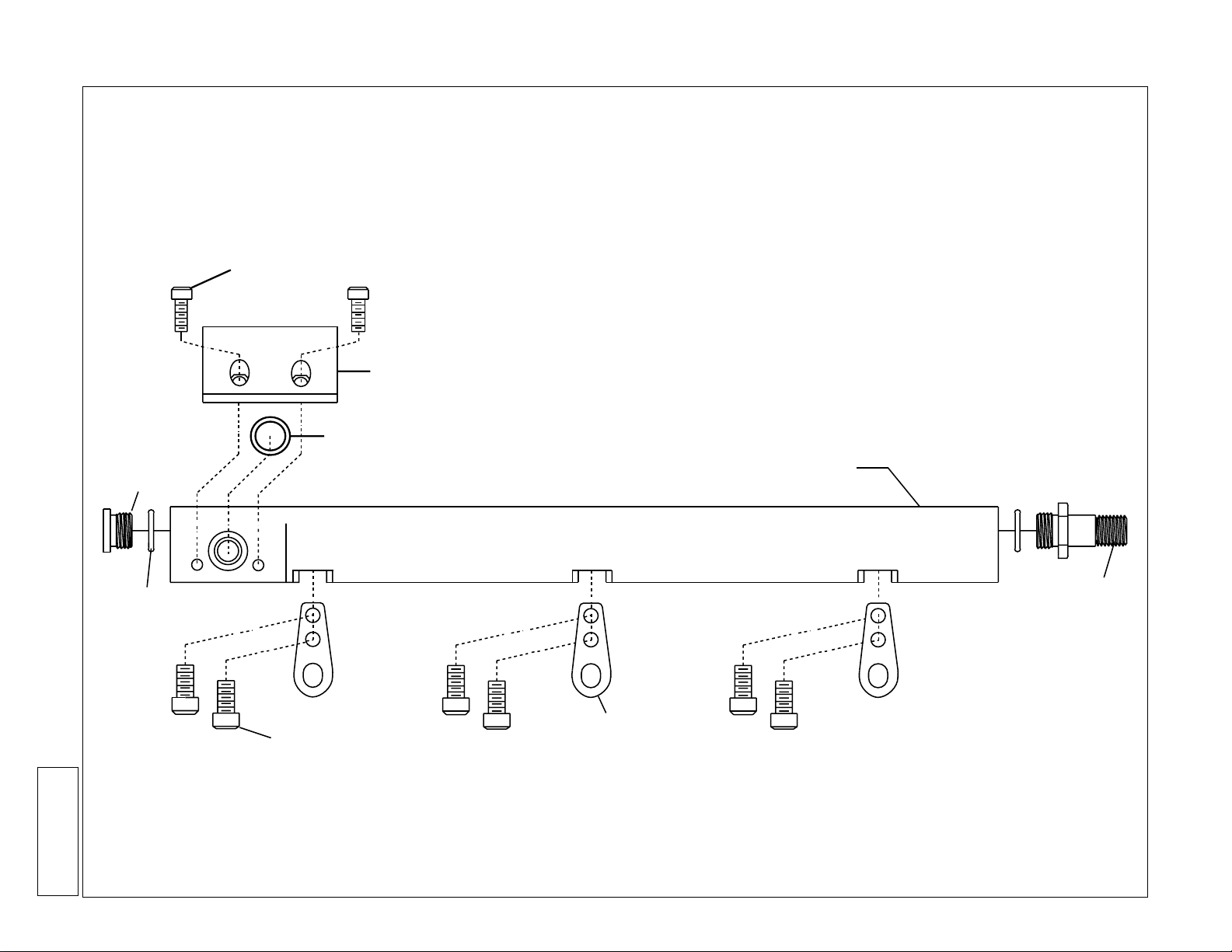
HONDA FUEL RAIL ASSEMBLY DIAGRAM
('92-'95 1.6L SOHC VTEC)
10-24 x 1/2” SHCS
REGULATOR
ADAPTER
O-RING
MAXFLOW® POWER RAIL
3
PLUG
All Rights Reserved. Intl. Copr. Secured
©2000 Vortech Engineering, Inc.
12JUL00 V 1.0
P/N:007052
-6 O-RING
10-24 x 3/8” SHCS
MOUNTING TAB
Figure 1
FUEL LINE/
RAIL ADAPTER
 Loading...