

Page 1
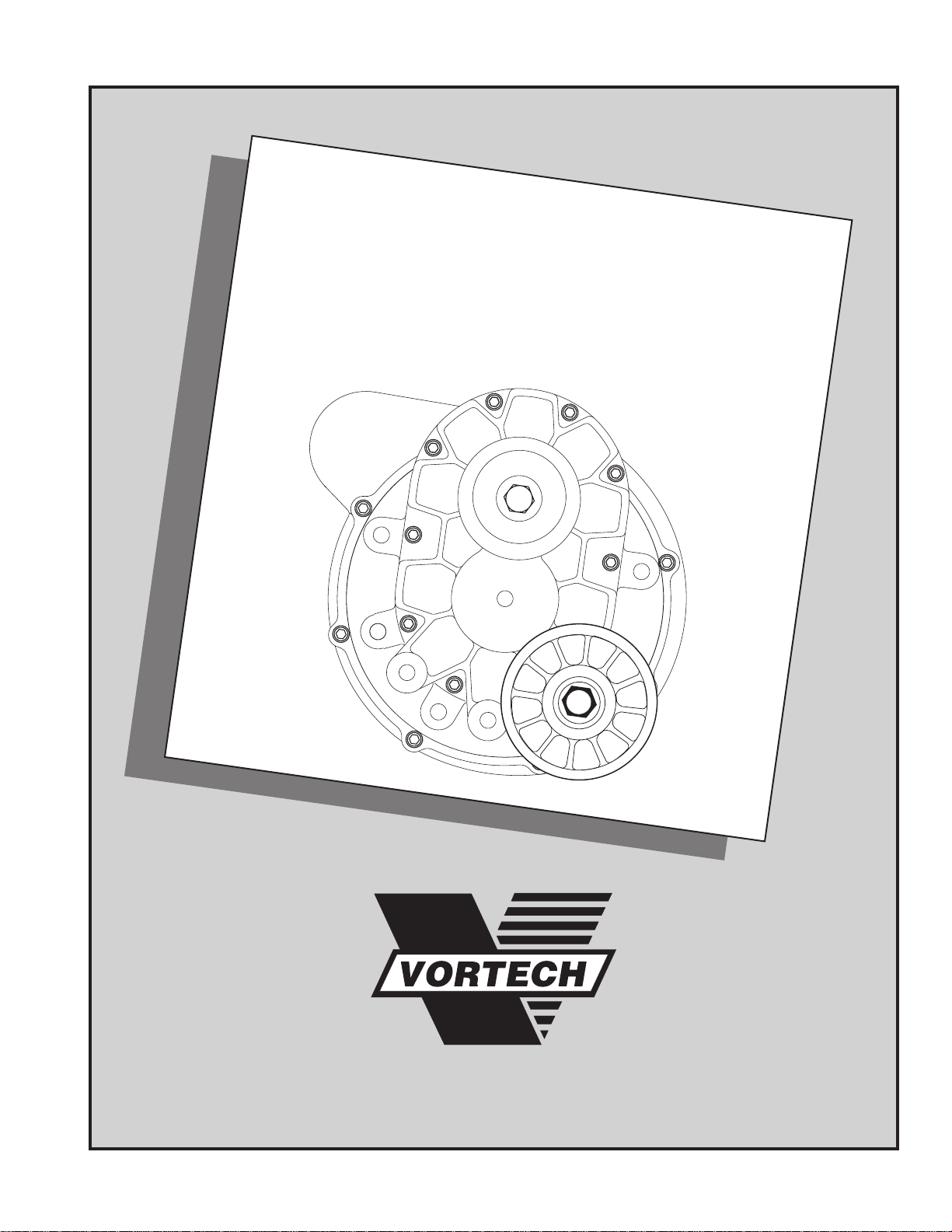
Dodge 5.2/5.9 Truck
Supercharger System
Installation Instructions for
‘91-‘95 Dakota & ‘94-‘95 Ram/T-300
50 State Smog Legal per CARB EO # D-213-10
®
ENGINEERING, INC.
1650 PACIFIC AVENUE • CHANNEL ISLANDS, CA 93033-9901
© 1997
VORTECH
®
all rights reserved. International Copyrights Secured 1-3-1994
Page 2

NOTICE
This product is protected by state common law,
copyright and/or patent. All legal rights therein are
reserved. The design, layout, dimensions,
geometry , and engineering features shown in this
product are the exclusive property of Vortech
Engineering, Inc. This product may not be copied
or duplicated in whole or part, abstractly or
fundamentally, intentionally or fortuitously, nor
shall any design, dimension, or other information
be incorporated into any product or apparatus
without prior written consent of Vortech
Engineering, Inc.
IMPORTANT
1996 models equipped with 5.9L engines may
require an upgrade to 1995 model 5.9L fuel
injectors. 1995 and earlier units have slightly higher
fuel flow capacity and allow more efficient engine
operation on supercharged applications.
®
ENGINEERING, INC.
1650 Pacific Avenue, Channel Islands, CA 93033 • (805) 247-0226
FAX (805) 247-0669 • http://www.vortecheng.com • M-F 8AM - 4:30PM (PST)
Page 3

SPECIAL NOTICE CONCERNING THE
CRANE IGNITION SYSTEM
The ignition system, manufactured by Crane Electronics,
included in this kit is serviced exclusively by the manufacturer.
Crane Electronics warrants this product to be free from defects
in material and workmanship under normal use and if properly
installed for a period of one (1) year from the date of purchase.
In case of malfunction, this unit will be repaired free of charge
according to the terms of the warranty. If found to be defective
as mentioned above, it will be repaired or replaced if returned
prepaid along with proof of date of purchase. This shall
constitute the sole remedy of the purchaser and the sole liability
of Crane Electronics and/or Vortech Engineering, Incorporated.
To the extent permitted by law, the foregoing is exclusive and
in lieu of all other warranties or representations whether
expressed or implied, including any implied warranty of
merchantability or fitness. In no event shall Crane Electronics
and/or Vortech Engineering, Incorporated, be liable for labor
charges, special or consequential damages.
When returning this unit for service, proof of purchase must be
supplied for warranty verification. After the warranty period has
expired, repair service is charged between a minimum and
maximum charge. In either case, please send the unit prepaid with proof of purchase to the attention of:
Crane Electronics
Customer Service Department
530 Fentress Boulevard
Daytona Beach, Florida, 32114
(904) 258-6167
(904) 258-6174 Fax
www.cranecams.com
The repaired unit will be returned as soon as possible after
receipt, COD for any charges. Be sure you include a detailed
account of any problems experienced, the type of vehicle and
any modifications.
Should you have any technical or installation questions
regarding this unit, contact Vortech Engineering, Incorporated,
directly at (805) 247-0226.
®
ENGINEERING, INC.
Page 4
Installation Instructions for
'91-'94 Dodge Dakota & '94-'95 Dodge Ram/T300
50 State Smog Legal, as per CARB EO #D-213-10
'95-'96 Dodge Dakota & '96 Dodge Ram/T300
49 State Smog Legal
Congratulations on selecting the best performing and best backed automotive
supercharger available today... the VORTECH® V-1® Supercharger!
Before beginning this installation, please read through this entire instruction booklet and the Owner's
Manual which includes the Vortech V-1 Supercharger Limited Warranty, the Care & Feeding Guide, and
the Extended Service Program & Application Form.
Vortech supercharger systems are performance improving devices. In most cases, increases in torque of 30 to
35% and horsepower of between 35 and 45% can be expected with the boost levels specified by Vortech
Engineering. This product is intended for use on healthy, well maintained engines. Installation on a worn-out or
damaged engine is not recommended and may result in failure of the engine as well as the supercharger.
Vortech Engineering is not responsible for engine damage. Installation on new vehicles will not harm or
adversely affect the break-in period so long as factory break-in procedures are followed.
For best performance and continued durability, please take note of the following key points:
1. Use only premium grade fuel 92 octane or higher (R+M/2).
2. The engine must have stock compression ratio.
3. If the engine has been modified in any way, check with Vortech prior to using this product.
4. Always listen for any sign of detonation (pinging) and discontinue hard use (no boost) until problem is resolved.
5. Perform an oil and filter change upon completion of this installation and prior to test driving your vehicle.
Thereafter, always use a high grade SF rated engine oil or a high quality synthetic, and change the oil and filter
every 3,000 miles or less. Never attempt to extend the oil change interval beyond 3,000 miles, regardless
of oil manufacturer's claims, as potential damage to the supercharger may result.
6. Before beginning installation, replace all spark plugs that are older than 1 year or 10,000 miles with original heat
range plugs as specified by the manufacturer and reset timing to factory specifications (follow the procedures
indicated within the factory repair manual and/or as indicated on the factory underhood emissions tag). Do not
use platinum spark plugs unless they are original equipment. Change spark plugs every 15,000 miles and
spark plug wires every 50,000 miles or earlier.
TOOL & SUPPLY REQUIREMENTS
Factory repair manual
Timing light
3/8" drive and socket set: SAE and metric
1/2" drive and socket set: SAE and metric
3/8" NPT tap, 3/8-16 tap and handle
Adjustable wrench
Open end wrenches: 5/16", 3/8", 7/16", 1/2", 9/16"
Center punch and a 5/8" tapered punch
3/8" fuel fitting disconnect tool
5 quarts SF rated quality engine oil, oil filter, and wrench
Flat #2 screwdriver
Phillips #2 screwdriver
Heavy grease
Silicone sealer
Drill motor
3/32" drill bit
Oil sender socket, Snap-on
If your vehicle has in excess of 10,000 miles since its last spark plug change, then you will also need:
Spark plug socket
NEW spark plugs
®
# A120
4CB020-010-6
Page 5
1991-1993 5.2L Dodge Dakota Truck
®
ENGINEERING, INC.
IMPORTANT: Before beginning installation, verify that all parts are included in the
kit. Report any shortages or damaged parts immediately.
Part No. 4CB218-060S
PARTS LIST
Part Number Description Quantity
2A228-080 SUPERCHARGER ASSEMBL Y 1
2A128-080 V-1S supercharger 1
2A037-312 3.125” supercharger drive pulley 1
4FA116-150 Idler pulley assembly 1
7J012-092 12 mm flat washer 1
8R101-001 6 rib pulley retainer assembly 1
4CB111-021 MOUNTING BRACKET ASSEMBLY 1
4CB010-010 Mounting bracket support 1
4CB010-034 Mounting plate 1
4CB010-040 Coil mount bracket 1
4CB011-021 Mounting bracket 1
4CB017-011 1/2" spacer 1
2A047-113 Belt 1
7A312-351 5/16-18 X 3-1/2” bolt 1
7A375-100 3/8-16 x 1” bolts 10
7A375-300 3/8-16 x 3" bolt 1
7A375-375 3/8-16 x 3-3/4” bolt 1
7F375-016 3/8-16 nut 1
7J375-044 3/8” SAE washers 10
7K375-040 3/8” AN960 flat washers 5
7U100-055 6" nylon tie wraps 2
4CB112-010 AIR INTAKE ASSEMBLY 1
4CB012-030 Air filter mount bracket 1
4CB012-040 Air filter body 1
4FA012-012 90° intake elbow 1
4GB012-010 Air filter covers 2
7E010-046 #8 x 3/4" sheet metal screws 8
7P625-002 5/8" hose barb 1
7R002-052 #52 hose clamps 4
7R002-056 #56 hose clamps 2
7R002-116 #116 hose clamps 2
7S350-200 3-1/2” x 2” sleeve 1
7U100-046 O-ring 1
7U100-055 6" nylon tie wraps 2
7U033-000 5/8" x 40" PCV hose 1
7U035-000 3-1/2" x 16" flex hose 1
7U035-000 3-1/2" x 24" flex hose 1
8H040-040 Air filter 1
4CB155-010 RADIATOR RESERVOIR 1
4CB055-010 Washer reservoir 1
7C011-075 10/32" x 3/4" bolt 1
7F010-032 10-32 nylock nut 1
7J010-001 #10 flat washers 2
4CB130-036 OIL DRAIN ASSEMBLY 1
7U030-036 1/2” x 22” oil drain hose 1
7P375-017 3/8” NPT x 1/2” straight hose barb 1
7R001-008 #8 stainless hose clamps 2
Part Number Description Quantity
4CB130-026 OIL FEED LINE ASSEMBLY 1
7U030-026 1/4” x 33” oil feed hose 1
7P125-027 1/8" NPT straight fitting 1
7P125-034 1/8" NPT x 1/8" NPT straight tee 1
7P125-103 1/8 NPT -4 x 45° male elbow 1
7P250-066 #4 swivel x 1/4” hose barb fittings 2
7P525-067 .500 crimp ferrules 2
4CB101-002 FUEL PUMP ASSEMBLY 1
4CB010-050 Mounting pump bracket 1
5W001-001 Wire tap 1
5W001-010 16-14GA female slides 3
5W001-011 16-14GA eyelet 1
5W118-021 10" 18GA black wire 1
5W118-034 156" 18GA red wire 1
7C011-075 10/32" x 3/4" bolts 4
7E010-046 #8 x 3/4" sheet metal screw 1
7E010-050 #12 x 1/2" sheet metal screws 2
7F010-032 10-32 nylock nuts 4
7F312-018 5/16-18 nut 1
7P312-002 1/4" NPT x 5/16" hose barb fitting 1
7R001-004 #4 hose clamps 4
7R003-008 1/2" adel clamp 1
7R003-024 1-1/2" adel clamps 2
7U100-055 6" nylon tie wraps 6
7U031-018 5/16" x 12" fuel hose 1
7U030-056 3/8" x 20" fuel hose 1
8F001-002 155 inline fuel pump 1
4CB238-068 FMU (with lines) 1
6Z110-111 12:1 fuel management unit 1
4CB145-156 Male fuel line assembly 1
4CB146-166 Female fuel line assembly 1
7U030-046 5/32” x 25” vacuum tube 1
7E010-046 #8 x 3/4" sheet metal screws 2
7U100-055 6” nylon tie wraps 2
4CD112-020 AIR DISCHARGE ASSEMBLY 1
4CB012-020 Discharge tube 1
4CB050-010 Intake plenum 1
4GB040-060 Air/plenum gasket 1
7A250-400 1/4-20 x 4" HXHD bolt 1
7J250-001 1/4" SAE washer 1
7R002-044 #44 hose clamps 4
7S275-200 2-3/4” x 2” sleeves 2
4CD110-060 Plenum stay assembly 1
8D001-001 Bypass valve 1
8H040-075 1" air filter 1
7U030-046 5/32" x 36" vacuum line 1
7P156-082 5/32" tee 1
7R002-016 #16 hose clamps 2
7U034-016 1" x 4" gas heater hose 1
Page 6
1994-1996
Dodge Dakota/Ram/ T-300 Truck
®
ENGINEERING, INC.
IMPORTANT: Before beginning installation, verify that all parts are included in the
kit. Report any shortages or damaged parts immediately.
Part No. 4CD218-030S
PARTS LIST
Part Number Description Quantity
2A228-080 SUPERCHARGER ASSEMBL Y 1
2A128-080 V-1S supercharger 1
2A037-312 3.125” supercharger drive pulley 1
4FA116-150 Idler pulley assembly 1
7J012-092 12 mm flat washer 1
8R101-001 6 rib pulley retainer assembly 1
4CC111-021 MOUNTING BRACKET ASSEMBLY 1
4CB010-010 Mounting bracket support 1
4CB010-034 Mounting plate 1
4CB011-021 Mounting bracket 1
2A047-113 Belt 1
7A312-351 5/16-18 X 3-1/2” bolt 1
7A375-100 3/8-16 x 1” bolts 10
7A375-300 3/8-16 x 3" bolt 1
7A375-375 3/8-16 x 3-3/4” bolt 1
7F375-016 3/8-16 nut 1
7J375-044 3/8” SAE washers 10
7K375-040 3/8” AN960 flat washers 5
7U100-055 6" nylon tie wraps 2
4CC112-010 AIR INTAKE ASSEMBLY 1
4FA012-012 90° intake elbows 2
7P375-020 3/8" NPT x 5/8" straight hose barb 1
7R001-008 #8 hose clamp 1
7R002-056 #56 hose clamps 2
7S350-200 3-1/2” x 2” sleeves 2
7U100-055 6" nylon tie wraps 2
7U033-000 5/8" x 40" PVC hose 1
8H040-040 Air filter 1
4CC238-068 FMU (with lines) 1
6Z110-111 12:1 fuel management unit 1
4CC147-166 Fuel line assemblies 2
7E010-046 #8 x 3/4" sheet metal screws 2
7U100-055 6” nylon tie wraps 2
7U030-046 5/32” x 40” vacuum line 1
4CB130-036 OIL DRAIN ASSEMBLY 1
7U030-036 1/2” x 22” oil drain hose 1
7P375-017 3/8” NPT x 1/2” straight hose barb 1
7R001-008 #8 stainless hose clamps 2
4CB155-010 RADIATOR RESERVOIR 1
4CB055-010 Washer reservoir 1
7C011-075 10-32 x 3/4" bolt 1
7F010-032 10-32 nylock nut 1
7S010-001 #10 flat washers 2
4CB130-026 OIL FEED LINE ASSEMBLY 1
7U030-026 1/4” x 33” oil feed hose 1
7P125-027 1/8" NPT straight fitting 1
7P125-034 1/8" NPT x 1/8" NPT straight tee 1
7P125-103 1/8 NPT -4 x 45° male elbow 1
7P250-066 #4 swivel x 1/4” hose barb fittings 2
7P525-067 .500 crimp ferrules
Part Number Description Quantity
4CC101-002 FUEL PUMP ASSEMBLY 1
8F001-002 155 inline fuel pump 1
7R003-024 1-1/2" adel clamp 1
7R001-004 #4 hose clamps 4
7C011-075 10/32" x 3/4" bolt 1
7F010-032 10-32 nylock nut 1
7J010-001 #10 flat washers 2
7P250-050 1/4" NPT male branch tee 1
7P250-122 1/4" pipe thread AN917 tee 1
7P250-082 1/4" NPT x -4 90° fittings 2
7P250-045 1/4" NPT x 3/8" hose barb fittings 2
7P250-075 1/4" NPT 45° street elbpw 1
7P250-036 #4 flare to 1/4" NPT 1
7U030-056 3/8" x 3" PVC hose 1
7U030-050 12mm fuel hose 1
4CC145-156 Fuel line assembly A 1
4CC146-166 Fuel line assembly B 1
5W001-010 16-14GA female slides 3
5W118-021 10" 18GA black wire 1
5W118-036 75" 18GA red wire 1
5W001-011 16-14GA eyelet 1
5W001-001 Wire tap 1
7P250-047 1/4" NPT to 1/2" barb 1
5A101-009 H1-6 TR ASSEMBLY 1
5A001-009 HI-6 TR Ignition System 1
5W001-001 Wire Taps 2
5W001-009 16-14GA Male Slides 6
5W001-010 16-14GA Female Slides 6
5W001-011 16-14GA Eyelets 2
5W001-017 Large Ring Terminals 2
7E010-048 #10 x 3/4" HH Bolts 4
7U375-002 3.6" Velcro Latch 1
7U375-001 3.6" Velcro Hook 1
7U030-046 5/32" x 36" Vacuum Line 1
7P156-082 5/32" Tee 1
7U100-050 5/8" Grommet 1
7U100-055 6 Nylon Tie Wrap 1
4CD112-020 AIR DISCHARGE ASSEMBLY 1
4CB012-020 Discharge tube 1
4CB050-010 Intake plenum 1
4GB040-060 Air/plenum gasket 1
7A250-400 1/4-20 x 4" bolt 1
7J250-001 1/4" SAE washer 1
7R002-044 #44 hose clamps 4
7S275-200 2-3/4” x 2” sleeves 2
4CD110-060 Plenum stay assembly 1
8D001-001 Bypass valve 1
8H040-075 1" air filter 1
7U030-046 5/32" x 36" vacuum line 1
7P156-082 5/32" tee 1
7R002-016 #16 hose clamps 2
7U034-016 1" x 12" gas heater hose 1
Page 7
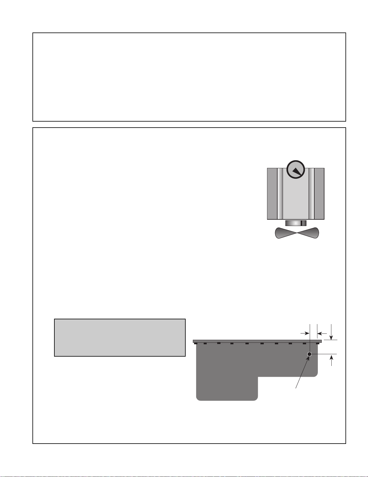
OIL PAN
PUNCH HOLE THROUGH
DOWN
2-1/2"
2-1/4"
1. PREPARATION/REMOVAL
A. Disconnect the battery negative cable.
B. Remove the accessory drive belt.
C. Remove the belt tensioner assembly and separate it from
the mounting bracket and set aside.
D. Disconnect and remove the crankcase breather hose.
E. Remove the entire air filter assembly.
F. Remove the radiator overflow reservoir and hose and set aside.
G. Remove the ignition coil and set aside.
2. OIL DRAIN
A. To provide an oil drain for the supercharger, it is necessary
to make a hole in the oil pan. The best way to provide this
hole is to punch the hole rather than drill. This tried and true
method has been used successfully since the early days of
turbocharging.
B. Rotate the engine until the mark on the damper is aligned
with the TDC (top dead center) tag on the front of the
engine. To aid you in this, remove the distributor cap and
watch the ignition rotor. It should end up between #5 and
#7 electrodes as shown in the graphic.
C. Temporarily detach the anti-roll bar (sway bar) strap mounts
at the frame and lower the bar out of the way.
D. Locate and mark hole per diagram. Remove paint around
the hole area. Layout the hole center per the diagram.
E. Use a small center punch to perforate the pan and expand
hole. Switch to a larger diameter punch and expand the
hole further to approximately 9/16" diameter. Most punches
are made from hexagon material and may be placed in a
socket with an extension to make this procedure easier.
F. Tap the hole with a 3/8" NPT tap approximately 1/4" deep.
Pack the flutes of the tap with heavy grease to hold chips.
Use a small magnet to check for any stray chips.
IGN. ROTOR
TDC
NOTE: This method of rolling over
the lip of the hole and tapping it
works very well if carefully done and
should cause no problems.
G. Thoroughly clean the threaded area. Apply
a small amount of silicone sealer to the
new threads. Apply more sealer to the 3/8"
NPT hose fitting and secure in hole. Make
sure a seal is formed all around the fitting.
H. Drain engine oil and change filter. Reattach
anti-roll bar mounts.
I. The drain hose will be attached to the fitting in later steps.
If your installation is going to be over several days we
suggest that you cover the fitting to protect it from dirt.
1
Page 8

3. RADIATOR OVERFLOW RESERVOIR
A. Disconnect and remove the coolant recovery
reservoir and hose.
B. Locate the new reservoir as shown in the
photo so that it is approximately one inch
above the frame. Mark and drill a 3/16" hole
through the fan shroud and secure with the
fastener provided.
C. Cut two inches from the stock hose and use
fitting to adapt the clear hose to the radiator
overflow fitting. Connect the clear hose from
the radiator overflow fitting to the reservoir.
RESERVOIR
4. MAIN MOUNTING BRACKET AND PLATE
A. It is necessary to provide clearance
between the dipstick and accessory
drive belt. Remove the bolt holding the
dip stick tube. Hold the tube about two
inches and gently bend rearward about
an inch. With the new fastener
resecure.
B. Mount the cast aluminum main
mounting bracket on the front of the
engine's right cylinder head using the
fasteners provided, as shown.
C. Please note that the 3-3/4" bolt also
ATTACH TO
EXHAUST MANIFOLD
holds the supercharger mounting plate.
This fastener must be threaded into its
hole loosely as a pilot while securing
the cast bracket with the other two,
5/16-18 x 3-1/2"
/16-18 X 3.5
then removed for installation of the
supercharger mounting plate.
D. Attach the stock belt tensioner to the
front of the supercharger mounting
plate as shown. Make sure the indexing
tab is engaged in the slot.
E. Now secure the plate and tensioner as
an assembly to the cast bracket.
F. Attach the support strut between the
supercharger mounting plate and the
second exhaust manifold stud. If you
have installed headers, you will need
to make a longer tube spacer to make
up the difference between the header
and manifold thickness. Secure with
the stainless steel bolt.
SUPPORT
SUPERCHARGER
GEARCHARGER
MOUNTING PLATE
MOUNTING PLATE
3/8-16 x 1"
3/8-16 X 1.0
MAIN MOUNTING
BRACKET
STOCK TENSIONER
3/8-16 x 1"
3/8-16 X 1.0
3/8-16 x 3"
3/8-16 X 3.0
3/8-16 x 3-3/4"
3/8-16 X 3.75
3/8-16 X 3.0
3/8-16 x 3"
2
Page 9

5. SUPERCHARGER MOUNTING
A. Attach the oil drain hose to the
drain fitting on the bottom of the
supercharger and secure with the
clamp provided. Make sure to
position the clamp housing to the
side so that it does not interfere
with the mounting plate.
B. Set the supercharger in place on
the plate and secure with the five
3/8-16 x 1" bolts and washers.
C. Attach the plastic idler pulley to
the inner most threaded boss on
the supercharger using the large
washer as a spacer in between
as shown.
6. SUPERCHARGER/ACCESSORY DRIVE BELT
A. The new longer accessory drive
belt is routed the same as the
original belt except for
accommodation of the
supercharger an idler pulley.
B. Route the belt around the outside
of the supercharger drive pulley
then around the inside of the idler
as shown.
C. The stock tensioner is used as
originally intended in its relocated
position.
NOTE: This drive belt is
custom made for Vortech
and is obtainable as a spare;
however, should an
emergency arise, a Gates
P/N K060113 six rib belt may
be used temporarily.
3
Page 10

7. OIL FEED LINE
A. Disconnect and remove the oil pressure sender
from the engine. The sender is found at the rear
of the intake manifold to the right side of the
distributor.
B. Install the supplied tee fitting into the block and
place the sending unit in the upper end. Install the
union fitting in the side port and orient the assembly
so that it points rearward and slightly outward
towards the passenger seat. Reconnect the
pressure sender connector.
NOTE: It is essential that the supercharger oiling orifice not be plugged;
therefore, do not use Teflon tape or
other sealant that could possibly cause
blockage. Use engine oil.
C. Attach the preassembled red oil hose onto the
fitting. Route the hose forward along the inside of
the right valve cover. Be careful not to rest the oil
hose or ignition wires on the EGR tube at the rear
of the head.
D. Before connecting the other end of the hose to the
supercharger, briefly crank over the engine in
order to purge the line of oil and remove any
contaminants from the line. Use a drain pan or
coffee can to catch the oil.
E. Place the 45° union fitting into the supercharger
fitting. Connect the hose to the 45° fitting.
TDC
4
Page 11

8A. AUXILIARY FUEL PUMP (1991-1993 Models Only)
A. An additional fuel pump is supplied to
insure that sufficient fuel is available to
theengine. This pump is mounted beside
the stock fuel filter beneath the truck.
B. Secure the steel bracket to the frame with
the fasteners provided, as shown.
C. Open, then close the fuel filler cap to vent
any residual pressure. Disconnect the
stock fuel hose where it exits the fuel filter
and place the hose on to the new fuel pump
outlet and secure with the clamp provided.
WARNING: Take great care to
minimize fuel spillage and always
have a second person stand by with a
fire extinguisher as a precaution.
D. Connect the filter outlet to the pump inlet
with the 5/16" to 3/8" adapter and 3/8" fuel
hose. Secure the hose and adapter with
the clamps provided and attach the hose to
ENGINE
the frame.
E. Place the two clamps around the new fuel
pump and then secure the clamps to the
new bracket and the existing one with the
fasteners provided.
F. Connect the negative (-) terminal of the fuel
pump to the existing fastener on the frame.
G. The positive terminal connects to the blue
wire at the fuel pump relay. Locate the
power distribution center near the brake
booster, unfasten it and turn it over.
H. The #5 relay is for the fuel pump. Splice into
the blue wire running to the relay directly
beneath it. Tie wrap the wire to the original
harness that runs down to the frame keeping
it away from moving or heated parts.
VACUUM LINE TO
MANIFOLD PRESSURE
FUEL MANAGMENT
UNIT (FMU)
HOSE ADAPTER
FUEL FEED LINE
STD. PUMP
FUEL TANK
NEW
ADDITIONAL
FUEL PUMP
FUEL RETURN
LINE
5
Page 12

8B. AUXILIARY FUEL PUMP (1994-96 Models Only)
A. An additional fuel pump is supplied to insure
that sufficient fuel is available to the engine.
This pump is mounted on the left side inner
fenderwell.
B. Open, then close the fuel filler cap to vent any
residual pressure. Disconnect the stock fuel
supply hose where it enters the fuel rail.
WARNING: Take great care to
minimize fuel spillage and always
have a second person stand by with a
fire extinguisher as a precaution.
C. Following the graphic on the next page,
inserthose assembly "A" into the factory feed
lin until it snaps into place.
D. Drill a .25" hole in the dimple located in the to
center of the left inner fenderwell.
NOTE: On ABS equipped vehicles,
the pump mounting position may vary
slightly. Remove the windshield
washer reservoir to gain access to
mounting area.
E. Attach the Vortech fuel pump to the fenderwell
with the outlet pointing forward using the
supplied adel clamp and #10 hardware. See
photo at right.
F. Attach the supplied length of red wire from the
(+) terminal on the pump through the firewall to
the fusebox. Use the power from the heater
blower fuse.
G. Connect the ground wire from the (-) terminal
on the pump to the existing ground bolt in the
fender apron.
H. Assemble the brass fittings as shown an
connect hose assembly "B" to the fuel rail.
6
Page 13

8B. AUXILIARY FUEL PUMP (1994-96 Models Only)
FACTORY FUEL LINE
INLET
1/4" ADAPTER
OUTLET
1/4" x 18" HOSE
1/4" x 18" HOSE ASSEMBLY "A"
1/4" NPT x 45°
1/4" x 45°
FLARE
FLOW
#4 x 1/4" NPT 90°
1/4" NPT TEE
3/8" x 1/4" NPT
3/8" x 3"
SOFT HOSE
#4 HOSE
CLAMP (x4)
ADEL CLAMP
155L INLINE
PUMP
3/8" x 3"
MPI HOSE
5/16" x 30" HOSE ASSEMBLY "B"
3/8" x 1/4" NPT
5/16" FEMALE
BARB x 1/4" NPT
1/4" NPT
MALE BRANCH TEE
#4 x 1/4" NPT 90°
7
Page 14

9A. FUEL MANAGEMENT UNIT
(1991-1993 Models Only)
A. Place the fuel management unit (FMU) on
the firewall just below the rubber seal and
inward of the two dimples in the sheet metal
as shown in the photo. Mark and drill two
3/32" holes and secure the unit with the
sheet metal screws provided.
B. Disconnect the fuel rail RETURN line at the
fuel rail. It will be necessary to use a special
disconnect tool to accomplish this.
C. Connect the RETURN line to the adapter
fitting that runs from the outlet fitting on the
bottom of the FMU.
D. Connect the FMU inlet hose (the hose
running to the 90° fitting on the side of the
FMU) to the fitting on the bottom of the stock
fuel regulator.
E. Attach the supplied vacuum line from the
fitting on top of the FMU to the small vacuum
fitting on the driver's side of the intake
manifold. See graphic on page 9.
F. Use tie wraps to secure the lines.
OUTLET
FUEL FROM
HERE
RETURNS
TO TANK
CONNECT TO MANIFOLD
VACUUM/PRESSURE
INLET
FUEL LINE
FROM
STOCK
REGULATOR
9B. FUEL MANAGEMENT UNIT (1994-96 Models Only)
A. Using the photo on page 6 as a reference, place the fuel
management unit (FMU) on the left side fender apron in
between the windshield washer reservoir and the power
distribution box. Mark and drill two 3/32" holes and secure
the unit with the sheet metal screws provided.
NOTE: On ABS equipped vehicles,
the fuel management unit must be
mounted on the firewall next to the
brake booster.
8
Page 15

9B. FUEL MANAGEMENT UNIT
(1994-96 Models Only) cont'd.
B. Connect the FMU inlet hose (the
hose running to the 90° fitting on
the side of the FMU) to the brass
90° fitting on the exit side of the
secondary fuel pump.
C. Connect the FMU outlet hose to
the brass #4 flare fitting located
before the secondary pump inlet.
D. Attach the supplied vacuum line
from the fitting on top of the FMU to
the small vacuum fitting on the
driver's side of the intake manifold.
See graphic.
E. Use tie wraps to secure the lines.
ATTACH FMU TO
SMALL VACUUM
CONNECTION
FUEL RAIL
FUEL
INJECTORS
INTAKE
MANIFOLD
DRIVER'S SIDE
10. DISCHARGE PLENUM AND DUCT
A. Remove the air filter hold-down bolt
from the bracket in the center of the
throttle body. Fit the 1/4-20 x 4-1/4" bolt
into the bracket and secure with the nut
provided.
B. Fit the discharge plenum, with the
gasket, onto the throttle body and tighten
the nut to position.
C. Secure the discharge duct in place with
the clamps and sleeves provided.
D. Fit the bypass valve to the 1" barb on
the discharge tube using the length of
1" heater hose and #16 hose clamps.
(See graphic for proper assembly.)
Attach the 1" K & N filter to the discharge
portion of the bypass valve. Tighten
clamps.
E. Connect the supplied piece of 5/32"
vacuum hose to the nipple located on
the bottom of the bypass valve. Tie the
opposite end of the hose into the FMU
vacuum/boost reference line using the
supplied 5/32" brass tee.
5/32" VACUUM
HOSE
CONNECT TO
MANIFOLD
VACUUM/BOOST
9
Page 16

11A. IGNITION COIL RELOCATION (1991-1993 Models)
A. Remount the ignition coil on top of the intake
manifold between the alternator and the
plenum as shown.
B. Using the 1/8" thick bracket and the 3/8" nut
and washer on the existing front stud and the
existing bolt at the rear secure in place.
C. Carefully reroute the coil wire and secure with
tie wraps.
11B. IGNITION COIL RELOCATION (1994-96 Models only)
A. Remove the coil from the mounting bracket
and modify the bracket as shown. Remount
the coil to the bracket 180° from the original
position (with the plug lead towards the front of
the vehicle).
B. Attach the coil assembly to the threaded boss
on the intake manifold using the existing
alternator brace bolt.
FRONT OF
VEHICLE
CUT OFF AND DISCARD
APPROX.
1-3/4"
10
Page 17

12. IGNITION/BOOST CONTROL
A. Mount the ignition box in the engine
compartment onto the flat area near
the fuse box and passenger side
headlight. Use the supplied #10
sheet metal screws to secure. (See
graphic.)
B. Route the heavy black cable to a
clean ground. Route the heavy red
cable to the (+) positive terminal
located on the front side of the under
hood fuse box.
C. Locate the ignition coil plug-in
connector (grey and green wires)
on the vehicle wiring harness near
the original spring tensioner
location. Cut the connector from the
harness leaving 2-3" of wire
remaining on the connector.
NOTE: 1996-1997 models
have a slightly different coil
plug location and do not need
wire extensions.
PASSENGER SIDE ENGINE COMPARTMENT
FUSE BOX
(+) TERM
(–) TERM GROUND
VACUUM
RESERVOIR
RANE
®
C
HI-6TR
cams
FRONT OF VEHICLE
(VIEW FROM TOP)
CAPACITIVE DISCHARGE IGNITION
WITH AUTO-SEQUENCE REV LIMITER
FRAME RAIL
D. Extend the wires on the coil
connector using the supplied grey and green wires. Connect
the grey and green extensions to the black and orange
wires from the ignition box. Connect the remaining wires
following the diagram on the following page.
E. Mount the timing retard control knob and the map sensor in
the drivers compartment underneath the dash. The knob
control must be in an accessible position from the drivers seat.
F. Attach one end of the supplied 5/32" vacuum line to the map
sensor. Route the red and blue (or brown) wires along with
the vacuum line through the firewall.
G. Connect vacuum line and wiring harness following graphic
on the next page.
11
Page 18

12. IGNITION/BOOST CONTROL INSTALLATION, cont'd.
NOTE: 1996-1997 models do not
require extensions to properly wire
ignition assembly.
MAIN WIRING
HARNESS
GREY
GREEN
TO BATTERY +
HEAVY RED
HEAVY BLACK
TO GROUND
C
RANE
cams
®
HI-6TR
CAPACITIVE DISCHARGE IGNITION
WITH AUTO-SEQUENCE REV LIMITER
GREEN TACH (TAPE UP)
GREY MAGNETIC TRIGGER HARNESS (TAPE UP)
SUPPLIED MAP SENSOR
IGNITION COIL
CONNECTOR
GREY
GREEN
WIRE TAP
RED
WHITE
BLACK
ORANGE
GREEN
GREY
WHITE
RED
30" SUPPLIED
WIRE EXTENSIONS
SOLDER AND
SHRINK
SLEEVE
CONNECTORS
BLACK
ORANGE
MANIFOLD
VACUUM
3 WIRE HARNESS
BLUE OR BROWN (RETARD INPUT)
RED
RANE
T
E
ELECTRONICS
R
C
HI-6TR
TIMING RETARD CONTROL
12
YELLOW (TAPE UP)
BLACK (GROUND)
A
R
D
Page 19

13. IGNITION/BOOST CONTROL UNIT OPERATION
A. The Ignition/Boost Control unit
is designed to retard ignition in
relation to boost.
B. The unit is adjustable from 0° of
ignition retard to 4°of ignition retard
for each pound of boost, up to a
maximum of 20°
C. Using the middle position (knob
pointing straight up) as a starting
place, adjust the ignition retard
knob until just beyond the point of
detonation. Use third gear for testing
in a safe area or road. Adjust the
retard according to changes in
altitude and fuel quality.
Caution: It is extremely
important that the boost
retard never be turned to 0°
using pump fuel. It is
recommended that in stock
street applications, the knob
be at no less than 1°/lb.
Example
[5 psi at 3° per per lb.]
15
10
5
Degrees of Retard
5 7 10
psi Boost
[7 psi at 2° per per lb.]
Maximum Retard = 20°
Maximum Retard = 15°
[10 psi at 1/2° per per lb.]
13
Page 20

14A. AIR FILTER ASSEMBLY AND DUCT
(1991-1993 Models)
A. The air filter canister assembly is made up of a center
section and two end caps which house a cleanable high
flow element. The assembly is attached to a formed
aluminum bracket which is secured in place by either
screws or rivets to the inner fender. Position the filter
assembly so the front of the housing lines up with the front
of the ECM as shown in the photo above.
B. After positioning the entire housing and bracket assembly,
mark the bracket location; then with the bracket separated,
mark and drill the mount holes. Use a 3/32" drill bit.
C. Secure the bracket to the inner fender with the #8 sheet
metal screws provided.
D. Attach the air filter assembly to the bracket with the two
stainless clamps. Make sure the filtration element is securely
attached to the rear end cap and that the crank- case
breather fitting is in place.
E. Place the blue sleeve on the rear cap outlet and then the
plastic elbow. Connect the elbow to the supercharger with
the longer length of flex tube. Secure with the clamps
included.
F. Connect the filter inlet to the stock duct at the right side of
the grill opening.
G. Route the 5/8" breather hose from the fitting on the rear end
cap of the air filter assembly around the rear of the intake
manifold to the breather cap on the left valve cover. Secure
the hose with tie wraps as necessary.
14B. AIR FILTER ASSEMBLY AND DUCT (1994-96 Models Only)
A. Attach the two (2) 3-1/2" elbows, #56 clamps and
air filter to the supercharger inlet using the 3-1/2"
blue sleeves.
B. Route the 5/8" breather hose from the fitting on the
inlet duct, around the rear of the intake manifold to
the breather cap on the left valve cover. Secure the
hose with tie wraps as necessary.
14
Page 21

WARNING: Do not attempt to operate the
vehicle until ALL components are installed
and ALL operations are completed
including the final check.
15. FINAL CHECK
A. Reconnect the battery.
B. If your vehicle has gone over 10,000 miles since its last spark
plug change, you will need to change the spark plugs now
before test driving the vehicle.
C. Check all fittings, nuts, bolts and clamps for tightness. Pay
particular attention to oil and fuel lines around moving parts,
sharp edges and exhaust system parts. Make sure all wires
and lines are properly secured with clamps or tie wraps.
D. Check all fluid levels, making sure that your tank(s) is filled
with 92 octane or higher fuel before commencing test drive.
E. Start engine and allow to idle a few minutes, then shut off.
F. Recheck to be sure that no hoses, wires, etc. are near
exhaust headers or moving parts and for signs of any fluid
leakage. Check ignition timing to make sure it is set to stock
specifications before commencing test drive.
G. PLEASE TAKE SPECIAL NOTE: Operating the vehicle
without ALL the subassemblies completely and properly
installed may cause FAILURE OF MAJOR COMPONENTS.
H. Test drive the vehicle.
I. The supercharger drive belt stretches initially and will require
adjustment between 250 and 400 miles.
J. Read the STREET SUPERCHARGER SYSTEM
OWNER'S MANUAL AND WARRANTY REGISTRATION
FORM within thirty (30) days of purchasing your supercharger
system to qualify.
15
®
ENGINEERING, INC.
© 1997 VORTECH® ENGINEERING, INC. all rights reserved
 Loading...