

Page 1
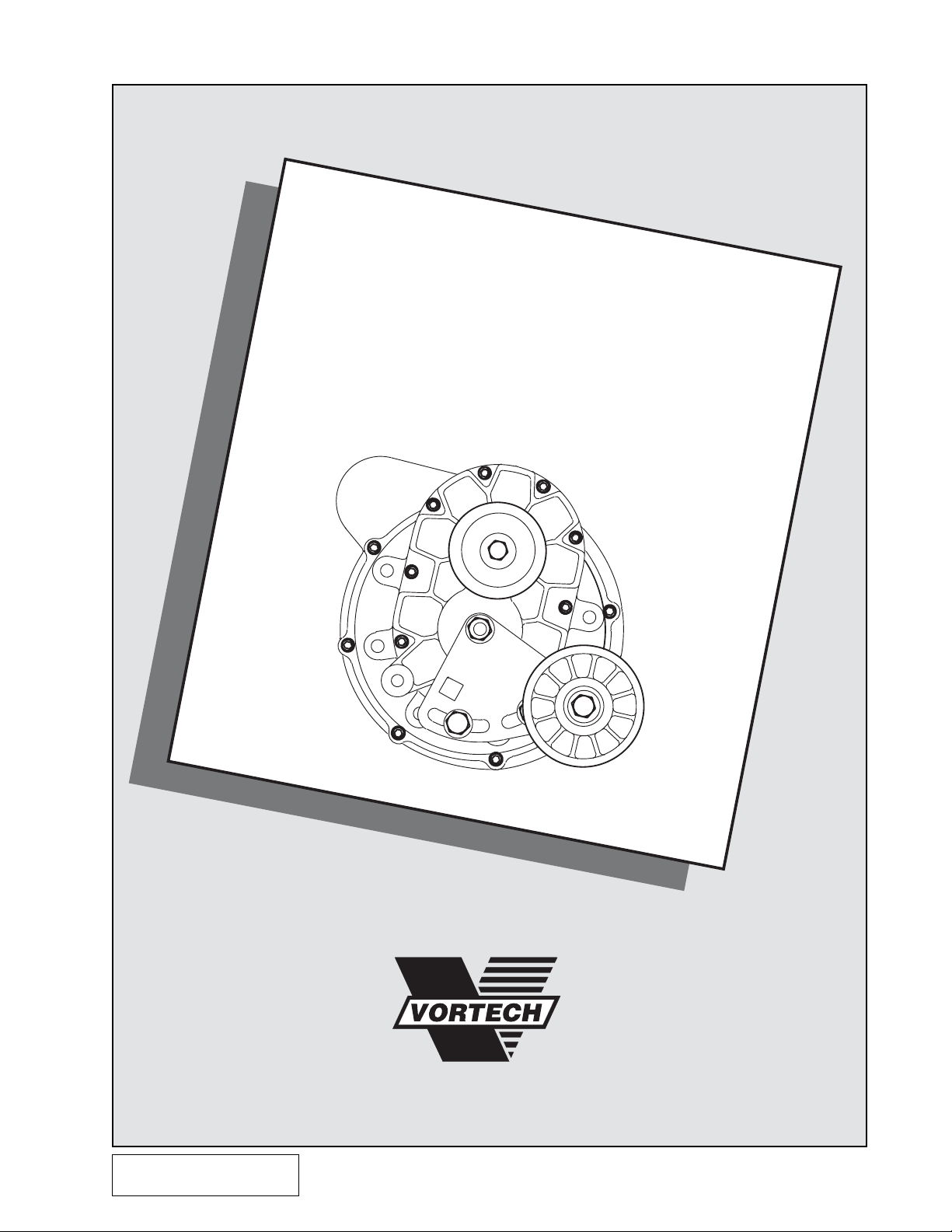
GM 5.0 and 5.7
T.P.I. F-Body
Supercharger System
Installation Instructions
50 State Smog Legal per CARB EO #D-213-17
1988-1992 Model Years
1650 PACIFIC AVENUE • CHANNEL ISLANDS, CA 93033-9901 • (805) 247-0226
FAX (805) 247-0669 • www.v ortechsuperchargers.com • M-F 8:00 AM - 4:30 PM PST
P/N: 4GF020-010
©2002 Vortech Engineering, LLC
All Rights Reserved, Intl. Copr. Secured
12JAN01 V1.1
(88-92 350 TPI Camaro(4GF V1.1))
®
ENGINEERING, LLC
Page 2

FOREWORD
Proper installation of this supercharger kit requires general automotive mechanic
knowledge and experience. Please browse through each step of this instruction
manual
job to a professional installer/technician. Please call Vortech Engineering for
installers in your area.
prior
to beginning the installation to determine if you should refer the
© 2001 VORTECH ENGINEERING, LLC
All rights reserved. No part of this publication may be reproduced, transmitted, transcribed,
or translated into another language in any form, by any means without written permission
of Vortech Engineering, LLC.
P/N: 4GF020-010
©2001 Vortech Engineering, LLC
All Rights Reserved, Intl. Copr. Secured
09JAN01 V1.0
(88-92 350 TPI Camaro(4GF V1.0))
ii
Page 3

Table Of Contents
FOREWORD ............................................................................................................. ii
TABLE OF CONTENTS ............................................................................................ iii
NOTICE..................................................................................................................... iv
TOOL & SUPPLY REQUIREMENTS......................................................................... v
MSD IGNITION SYSTEM.......................................................................................... vi
PARTS LIST 1988-1992 5.0/5.7 F-BODY ................................................................. vii
PONTIAC SUPPLEMENTAL INSTRUCTIONS ......................................................... ix
1. COMPONENT REMOVAL ............................................................................. 1
2. CRANKSHAFT PULLEY INSTALLATION ..................................................... 1
3. OIL DRAIN LINE............................................................................................ 2
4. OIL FEED LINE ............................................................................................. 3
5. AUXILLIARY PUMP ....................................................................................... 4
6. FUEL MANAGEMENT UNIT INSTALLATION ............................................... 5
7. MAIN BRACKET AND POWER STEERING PUMP...................................... 6
8. SUPERCHARGER MOUNTING.................................................................... 7
9. CANISTER RELOCATION ............................................................................ 8
10. ALTERNATOR WIRE EXTENSION ............................................................... 8
11. AIR FILTER, INLET DUCT AND DISCHARGE PLENUM............................... 9
12. WINDSHIELD WASHER RESERVOIR ......................................................... 10
13. IGNITION/BOOST CONTROL INSTALLATION............................................. 10
14. IGNITION/BOOST CONTROL UNIT OPERATION ....................................... 1 1
15. FINAL ASSEMBLY AND CHECK OVER ....................................................... 12
©2001 Vortech Engineering, LLC
iii
All Rights Reserved, Intl. Copr. Secured
09JAN01 V1.0
(88-92 350 TPI Camaro(4GF V1.0))
P/N: 4GF020-010
Page 4

NOTICE
This product is protected by state common law, copyright and/or patent. All legal
rights therein are reserved. The design, layout, dimensions, geometry, and
engineering features shown in this product are the exclusive property of Vortech
Engineering,LLC. This product may not be copied or duplicated in whole or part,
abstractly or fundamentally, intentionally or fortuitously, nor shall any design,
dimension, or other information be incorporated into any product or apparatus
without prior written consent of Vortech Engineering,LLC.
P/N: 4GF020-010
©2002 Vortech Engineering, LLC
All Rights Reserved, Intl. Copr. Secured
12JAN01 V1.1
(88-92 350 TPI Camaro(4GF V1.1))
iv
Page 5

1988 - 1992
GM 5.0 AND 5.7 F-BODY
Installation Instructions
50 State Smog Legal, as per CARB EO #D-213-17
Congratulations on selecting the best performing and best backed automotive
supercharger available today... the VORTECH
Before beginning this installation, please read through this entire instruction booklet and the Street
Supercharger System Owner's Manual which includes the Limited Warranty Program and the Warranty
Registration form and return envelope.
Vortech supercharger systems are performance improving devices. In most cases, increases in torque
between 30-35% and horsepower between 35-45% can be expected with the boost levels specified by Vortech
Engineering. This product is intended for use on healthy, well maintained engines. Installation on a worn-out
or damaged engine is not recommended and may result in failure of the engine as well as the supercharger.
Vortech Engineering is not responsible for engine damage.
Installation on new vehicles will not harm or adversely affect the break-in period so long as factory break-in
procedures are followed.
For best performance and continued durability, please take note of the following key points:
1. Use only premium grade fuel 92 octane or higher (R+M/2).
2. The engine must have stock compression ratio.
3. If the engine has been modified in any way, check with Vortech prior to using this product.
4. Always listen for any sign of detonation (pinging) and discontinue hard use (no boost) until problem is
resolved.
5. Perform an oil and filter change upon completion of this installation and prior to test driving your vehicle.
Thereafter, always use a high grade SF rated engine oil or a high quality synthetic, and change the oil
and filter at least every 3,000 miles. Never attempt to extend the oil change interval beyond 3,000
miles, regardless of oil manufacturer's claims as potential damage to the supercharger may
result.
6. Before beginning installation, replace all spark plugs that are older than 1 year or 10,000 miles with
original heat range plugs as specified by the manufacturer and reset timing to factory specifications
(follow the procedures indicated within the factory repair manual and/or as indicated on the factory
underhood emissions tag). Do not use platinum spark plugs unless they are original equipment.
Change spark plugs at least every 15,000 miles and spark plug wires every 50,000 miles.
®
V-2® supercharger!
TOOL & SUPPLY REQUIREMENTS
• Factory Repair Manual
• 3/8" socket and drive set: SAE & metric
• 1/2" breaker bar and 4" extension
• Flat #2 screwdriver
• Phillips #2 screwdriver
• Large screwdriver or pry bar
• Adjustable wrench
• Open end wrenches:
3/8", 7/16", 9/16", 5/8", 3/4", 7/8" and
a "Slimline" 19mm-Snap-On #LTAM1719
• 7/32" allen wrench
• Timing light
• Drill motor
• 21/64", 3/32" drill bits
• 3/8" NPT tap & handle
• Center punch
• 3/4" drift punch
• Silicone sealer
• Heavy grease
• Oil filter wrench
• Oil filter
• SF rated quality (or synthetic) engine oil
• Power steering pump pulley puller and installer
• Snap-On puller #CJ117B2 and installer #CJ113B
Note: If your vehicle has in excess of 10,000 miles since its last spark plug change, then you will need:
• Spark plug socket
• 8 new OE heat range spark plugs
©2002 Vortech Engineering, LLC
v
All Rights Reserved, Intl. Copr. Secured
12JAN01 V1.1
(88-92 350 TPI Camaro(4GF V1.1))
P/N: 4GF020-010
Page 6

SPECIAL NOTICE CONCERNING THE
MSD IGNITION SYSTEM
The MSD Boost Timing Master , manuf actured by Autotronic Controls
Corporation, included in this kit is serviced exclusively by the
manufacturer . A utotronic Controls Corporation warrants this product
to be free from defects in material and workmanship under normal
use and if properly installed for a period of one year from the date of
purchase. In case of malfunction, this unit will be repaired free of
charge according to the terms of the warranty . If found to be def ective
as mentioned above, it will be repaired or replaced if returned prepaid
along with proof of date of purchase. This shall constitute the sole
remedy of the purchaser and the sole liability of Autotronic Controls
Corporation and/or V ortech Engineering, Inc. To the extent permitted
by law, the foregoing is exclusive and in lieu of all other warranties
or representations whether expressed or implied, including any
implied warranty of merchantability or fitness. In no event shall
Autotronic Controls Corporation and/or V ortech Engineering, Inc. be
liable for labor charges, special or consequential damages.
When returning this unit for service, proof of purchase must be
supplied for warranty verification. After the warranty period has
expired, repair service is charged between a minimum and maximum
charge. In either case, please send the unit pre-paid with proof of
purchase to the attention of:
Autotronic Controls Corporation
Customer Service Department
12120 Esther Lama
Suite #114
El Paso, Texas, 79936
Phone: (915) 855-7123
Fax: (915) 857-3344
www.msdignition.com
The repaired unit will be returned as soon as possible after receipt,
COD for any charges. Be sure you include a detailed account of any
problems experienced, the type of vehicle and any modifications.
Should you have any technical or installation questions regarding
this unit, contact V ortech Engineering, Inc. directly at (805) 247-0226,
M-F 8:00AM-4:30PM (PST).
P/N: 4GF020-010
©2002 Vortech Engineering, LLC
All Rights Reserved, Intl. Copr. Secured
12JAN01 V1.1
(88-92 350 TPI Camaro(4GF V1.1))
vi
Page 7
1988-1992 5.0 and 5.7 F-Body
Part No. 4GF218-060SQ
®
ENGINEERING, INC.
IMPORTANT: Before beginning installation, verify that all parts are included in the kit. Report any
shortages or damaged parts immediately.
Part Number Description Quantity
2E228-060 V-2 SU GER ASSEMBLY 1
4GF111-021 MOUNTING BRACKET ASSEMBLY 1
4GF011-021 Mounting bracket 1
4GF111-021 Mounting plate 1
4GF017-041 .875 x 4.305 spacer C 1
4GF017-051 .875 x 2.305 spacer D 1
4GF017-011 Idler spacer 1
7A375-525 3/8-16 x 5- 1/4” bolts 2
7A375-300 3/8-16 x 3” bolt 1
7A375-100 3/8-16 x 1” bolts 7
7C010-030 M10-1.5 x 30mm bolt 1
7K375-040 3/8” AN960 flat washers 10
7J375-044 3/8” SAE washers 5
7L375-075 3/8” lock washer 1
7A375-550 3/8-16 x 5-1/2” bolts 2
7A375-17A 3/8-16 X 1-3/4” flat allen bolt 1
4GF016-160 Idler ribbed pulley 1
7C012-050 12mm x 1.75 x 50mm bolt 1
7G010-175 12mm x 1.75 nut 1
4GF112-010 AIR INTAKE ASSEMBLY 1
4FA012-012 90° intake elbow 2
4GF012-022 Intake elbow 1
7S350-300 3-1/2” x 3 sleeve 1
7S350-200 3-1/2” x 2” sleeve 1
7U035-000 3-1/2” x 14” flex hose 1
8H040-030 Air filter 1
7R001-008 #8 stainless hose clamps 4
7U030-036 1/2” x 24” oil drain hose 1
7P375-017 3/8” NPT x 1/2” straight hose barb 1
7J250-150 1/4” fender washer 1
7A250-074 1/4-20 x 3/4” bolt 1
7R002-056 #56 hose clamps 4
7R002-052 #52 hose clamps 4
7U375-052 3/8” vacuum cap 1
7S300-100 3” x 1” sleeves 1
5W001-007 3/16” x 8" shrink tube 1
5W118-025 18GA 18" standard black wire 1
5W118-032 18GA 18” standard red wire 1
5W118-075 18GA 18” standard orange wire 1
5W118-085 18GA 18” standard green wire 1
7P500-001 PVC hose mender 1
4GF112-020 AIR DISCHARGE ASSEMBLY 1
4GF012-020 Discharge tube 1
7S275-200 2-3/4” x 2 sleeve 1
7S400-200 4” x 2” sleeve 1
7R002-044 #44 hose clamps 2
7R002-064 #64 hose clamps 2
4GF116-010 CRANK PULLEY ASSEMBLY 1
4GF016-011 Crank pulley 1
4GB017-041 Crank pulley spacer 1
7B437-400 7/16-20 x 4” bolt 1
7J375-044 3/8” SAE washers 3
7L375-075 3/8” lock washers 3
2A046-988 Belt 1
2A046-605 Belt 1
7B375-275 3/8-24 x 2-3/4” bolts 3
4GF130-026 OIL FEED ASSEMBLY 1
7U030-026 1/4” x 37” oil feed hose 1
7P525-067 .500 crimp ferrules 2
7P250-066 #4 swivel x 1/4” hose barb fitting 2
7P250-036 #4 flare to 1/4” NPT 1
7P250-122 1/4” AN917 pipe thread tee 1
7P250-123 1/4” NPT x 1/2” nipple 1
7P250-075 1/4” NPT 45° street elbow 1
7P125-026 90° 1/8” NPT x #4 fitting 1
Part Number Description Quantity
4GF130-036 OIL DRAIN ASSEMBL Y 1
7U030-036 1/2” x 30” oil drain hose 1
7R001-008 #8 stainless hose clamps 2
7P375-017 3/8” NPT x 1/2” straight hose barb 1
7P375-033 3/8” NPT x 3/8” NPT street elbow 1
4GF155-010 WASHER RESERVOIR ASSEMBLY 1
4GF055-010 Washer reservoir 1
7U030-046 5/32” x 32” vacuum line 1
7U100-055 6” nylon tie wraps 4
7R003-020 1-1/4” adel clamp 1
7E010-050 #12 x 1/2” sheet metal screw 1
4FA111-032 BELT TENSIONER ASSEMBL Y 1
7J012-092 12mm flat washers 3
4FA011-032 Belt tensioner 1
7C012-050 12mm x 1.75 x 50mm bolt 1
4FA016-150 Smooth pulley tensioner 1
2A017-010 Idler pulley spacer 1
7C012-020 12mm x 1.75 x 20mm bolts 2
7C012-022 12mm x 1.75 x 22mm thin head bolt 1
7G010-175 12mm x 1.75 nut 1
4GF101-002 FUEL PUMP ASSEMBL Y 1
8F001-002 155 inline fuel pump 1
7R003-008 1/2” adel clamp 1
7R003-024 1-1/2” adel clamp 1
7P375-050 3/8” hose mender 1
7R001-004 #4 hose clamps 4
7U100-055 6” nylon tie wraps 6
5W001-011 16-14GA eyelet 1
5W001-010 16-14GA female slides 3
5W118-021 18GA 10” standard black wire 1
5W118-034 18GA 156” standard red wire 1
5W001-002 Fuse tap 1
7E010-050 #12 x 1/2” sheet metal screws 2
7E010-046 #8 x 3/4” sheet metal screw 1
7U031-018 5/16 x 6” fuel hose 1
4GF160-015 EVAPORATOR CANNISTER KIT 1
7U030-016 1/4” x 15” fuel hose 1
7U030-046 5/32” x 24” vacuum line 1
5W122-061 22GA 12” standard blue wire 1
5W122-251 22GA 12” standard white/black wire 1
5W001-037 3/16” x 3” shrink tube 1
5W001-012 22GA red solderless connectors 4
4GF150-012 ALTERNATOR WIRE KIT 1
5W122-161 22GA 16” standard brown wire 1
5W122-231 22GA 16” standard green wire 1
5W001-067 3/16” x 6” shrink tube 1
5W001-012 22GA red solderless connectors 4
4GF238-068 FMU (with lines) 1
6Z110-114 8:1 black fuel management unit 1
4GF145-156 12” fuel line assembly 1
4GF146-166 14” fuel line assembly 1
7U030-046 5/32” x 60” vacuum line 1
7E010-046 #8 x 3/4” sheet metal screws 2
7U100-055 6” nylon tie wraps 2
7R001-004 #4 hose clamps 2
PARTS LIST
vii
5A001-001 STAND ALONE IGNITION RETARD 1
©2002 Vortech Engineering, LLC
All Rights Reserved, Intl. Copr. Secured
12JAN01 V1.1
(88-92 350 TPI Camaro(4GF V1.1))
P/N: 4GF020-010
Page 8

P/N: 4GF020-010
©2002 Vortech Engineering, LLC
All Rights Reserved, Intl. Copr. Secured
12JAN01 V1.1
(88-92 350 TPI Camaro(4GF V1.1))
viii
Page 9

PONTIAC
SUPPLEMENTAL INSTRUCTIONS
1. RELOCATE BATTERY
A. Remove the evaporative canister from the right
front inner fender. Set aside for now.
B. Remove the battery from its stock location at left
front inner fender. Relocate battery to the right
inner fender utilizing the existing factory hardware to resecure it.
C. Coil and secure the excess length of positive
battery cable with wire ties provided.
D. Clip and extend the 8 gauge alternator wire
connector with wire provided.
2. MOUNT THE VORTECH SUPPLIED
WASHER RESERVOIR
A. Locate the new washer fluid reservoir inward of
the battery on the right side of the engine bay.
3. RELOCATE THE EVAPORATIVE CANISTER
A. The evaporative canister must be relocated to
the right front behind the splash panel in front of
the right wheel.
B. For specific details locate item in section 9.
(CANISTER RELOCATION) this instruction
manual and follow the operations listed applying them to the right side of the vehicle.
FRAME
FRAME
SPACER
SP ACER
ix
EV APORATIVE
EVAPORATIVE
CANISTER
CANISTER
©2002 Vortech Engineering, LLC
All Rights Reserved, Intl. Copr. Secured
12JAN01 V1.1
(88-92 350 TPI Camaro(4GF V1.1))
P/N: 4GF020-010
Page 10

P/N: 4GF020-010
©2002 Vortech Engineering, LLC
All Rights Reserved, Intl. Copr. Secured
12JAN01 V1.1
(88-92 350 TPI Camaro(4GF V1.1))
x
Page 11

1. COMPONENT REMOVAL
A. Disconnect the battery (negative lead).
B. Remove and set aside the following compo-
nents:
• Air inlet bellows
• Air filter cover assembly and elements and
the panel below filter
• Windshield washer reservoir
• Accessory drive belt
• Crankshaft pulley
• Alternator (disconnect wiring)
• Power steering pump pulley (use puller)
• Power steering pump and bracket (DO NOT
disconnect lines)
• Power steering bracket
2. CRANKSHAFT PULLEY INSTALLATION
A. Remove the crankshaft pulley from the engine if
not already done.
B. Place the
and crank pulley inside the stock pulley.
C. Line up bolt holes and, if necessary, press
pieces together.
D. Reinstall the pulleys as a unit onto the crank-
shaft balancer assembly using three 3/8-16 x 2
3/4" bolts and one 7/16-20 x 4" center bolt.
Vortech provided crank pulley spacer
NEW ADDITIONAL PULLEY
CENTER BOLT: 7/16-20 x 4-1/4"
3 BOLTS: 3/8-24 x 2-3/4"
SPACER
©2002 Vortech Engineering, LLC
1
All Rights Reserved, Intl. Copr. Secured
12JAN01 V1.1
(88-92 350 TPI Camaro(4GF V1.1))
P/N: 4GF020-010
Page 12

3. OIL DRAIN LINE
A. Raise the front of the ve-
hicle and support with appropriate jack stands.
B. To provide an oil drain for
the supercharger, it is necessary to make a hole in the
oil pan. It is best to punch
the hole rather than drill.
Remove paint around the
hole area so that it does not
flake into the pan.
C. Make a mark on the oil pan
on the driver’s side ahead
of the oil filter. The mark
should be 3" below the third
bolt from the rear of the pan.
D. Use a small center punch to perforate the pan
and expand the hole. Switch to a larger diameter
punch and expand the hole further to approximately 9/16" diameter. Most punches are made
from hexagon material and may be placed in a
socket with an extension to make this procedure
easier.
E. Tap the hole with a 3/8" NPT tap approximately
1/4" deep. Pack the flutes of the tap with heavy
grease to catch and hold the chips. Once the tap
is removed, it must be cleaned and repacked
before tapping is resumed. Use a small magnet
to check for any stray chips after tapping procedure.
F. Thoroughly clean the threaded area with ac-
etone or other solvent. Apply a small amount of
silicone sealer to the new threads. Apply more
sealer to the threads of the 3/8" NPT 90° fitting
and secure it in the hole with the hose fitting
pointing forward and slightly upward. Make
sure a seal is formed all around the fitting at the
NOTE: This method of rolling over the lip of
pan.
the hole and tapping it works well if
CAREFULLY done and should cause
no problems.
OIL PAN
PUNCH HOLE THROUGH
DOWN 3"
OIL FILTER
IN-LINE
THIRD BOLT
G. Route the line forward along the top rail of the oil
pan and secure to pan bolts with the clamps
provided. Temporarily cover end of hose and
secure out of the way.
H. Drain and replace engine oil and change filter.
P/N: 4GF020-010
©2002 Vortech Engineering, LLC
All Rights Reserved, Intl. Copr. Secured
12JAN01 V1.1
(88-92 350 TPI Camaro(4GF V1.1))
2
Page 13

4. OIL FEED LINE
A. The supercharger uses en-
gine oil for lubrication and
must have an oil feed line
connected to a filtered oil
access on the engine and
an oil return or drain. The
return is a gravity drain and
should be routed so a
gradual drop is provided and
connected to the oil pan
above oil level and away
from suspension components or exhaust headers or
pipes.
WARNING: The oil system contains a small
orifice that is easily plugged. DO
NOT use any type sealant on any
of the threads. Instead use clean
engine oil. Disassemble and blow
out entire line if you have any
doubts.
B. Remove the oil pressure sending unit located on
the engine block just above the oil filter. Fit the
1/4" NPT tee fitting with the 1/4" NPT to flare
adapter fitting provided. Refit the sending unit
into the 45° fitting on the end.
C. Connect the 1/4" oil feed line to the 1/4" NPT to
adapter fitting. Route the line forward along the
top rail of the oil pan next to the drain line and
then upward, towards the supercharger future
location. Secure to the drain line with the tie
wraps provided.
D. Temporarily cover the end of the hose and
protect it from dirt until connecting to the supercharger.
CLAMPS
TIE WRAPS
OIL PAN
ENGINE BLOCK
Title: TPI OIL & DRAIN LINES
ARTWK CHEV 2 8-24-92
©2002 Vortech Engineering, LLC
3
All Rights Reserved, Intl. Copr. Secured
12JAN01 V1.1
(88-92 350 TPI Camaro(4GF V1.1))
P/N: 4GF020-010
Page 14

5. AUXILIARY FUEL PUMP
A. Open the fuel fill cap briefly to vent any pressure. Find the
stock 3/8" fuel
valve cover.
B. Cut the stock hose approximately 7" from the fitting nearer
the engine and fit the new hose with the "splice fitting" into
the engine end and secure with a clamp.
C. Place the other end of the new hose on the pump outlet
fitting (brass fitting) and secure with a clamp.
D. Place the fuel pump inlet into the end of the remaining
portion of hose (coming from the tank) and secure with the
provided clamp.
E. Mount the fuel pump to the flat surface ahead of the inner
fender with the hold-down clamp provided as shown in the
graphic.
F. Connect the black wire to the fuel pump and then to a clean
ground and secure.
G. Connect the positive wire first to the pump and then to the
+
12V terminal at the fuse box using the adapter provided. It
is important that the source is turned on with the key and
remains on during cranking mode. A BLANK fuse will
usually work for this purpose.
H. Make sure the wires are carefully and properly secured.
feed line near the front of the engine's left
FEED
LINE
FUEL RETURN LINE:
CUT STOCK LINES AND SPLICE TO FMU
CUT, LEAVE 7"
FUEL FEED LINE:
CUT STOCK LINE AND CONNECT TO
PUMP INLET. USE SPLICE FITTING TO
CONNECT TO ENGINE LINE.
RETURN
LINE
P/N: 4GF020-010
©2002 Vortech Engineering, LLC
All Rights Reserved, Intl. Copr. Secured
12JAN01 V1.1
(88-92 350 TPI Camaro(4GF V1.1))
4
Page 15

6. FUEL MANAGEMENT UNIT INSTALLATION
A. Mount the fuel management unit (FMU) to
the inner fender on the driver's side. Placement should be on the vertical flat area near
the top of the fender above and just rearward of the horn assemblies. Using the
FMU mounting bracket as a template, mark
and drill two 3/32" holes. Use the sheet
metal screws in the kit to secure.
B. It is necessary to plumb the FMU into the
fuel return line. Start by cutting the fuel
return line 7" from the end at the engine.
C. Using the hose splice connect the 14" fuel
line supplied to the 7" length of stock hose
and connect to the FMU inlet.
D. With the second hose splice connect the 12"
fuel line provided to the other end of the cut
fuel line. Connect the other end to the outlet
fitting on the FMU.
E. Connect the 5/32" vacuum line from the
FMU to the intake manifold fitting and secure.
NOTE: Make sure you have routed all fuel
lines away from all moving parts,
sharp edges, exhaust pipes and
manifold. Secure the fuel lines with
the tie wraps.
OUTLET
(FUEL FROM
HERE
RETURNS
TO TANK)
CONNECT TO MANIFOLD
VACUUM/PRESSURE
INLET
(FUEL LINE
FROM
STOCK
REGULATOR)
ENGINE
FUEL TANK
STANDARD
PUMP
FUEL FEED LINE
ADDITIONAL
FUEL PUMP
FUEL
MANAGEMENT
UNIT (FMU)
FUEL
RETURN
LINE
©2002 Vortech Engineering, LLC
5
All Rights Reserved, Intl. Copr. Secured
12JAN01 V1.1
(88-92 350 TPI Camaro(4GF V1.1))
P/N: 4GF020-010
Page 16

7. MAIN BRACKET AND POWER STEERING PUMP
A. Temporarily install the main bracket on the
engine using two of the 3/8-16 x 5 1/2" bolts as
pilots to position the bracket to the cylinder
head. Remove the fuel line bracket and carefully bend the fuel lines as necessary to permit
bracket installation.
B. Install the flat head socket bolt in the chamferred
hole and secure to 32 ft/lb torque.
C. Using the three original fasteners and the one
fastener provided in the kit, secure the power
steering pump to the mounting plate.
D. Loosely attach the supercharger mounting plate
to the new main mounting bracket as shown. It
will be necessary to carefully bend the power
steering pump lines at both the pump and the
steering box to achieve a proper fit so that no
rubbing occurs when the engine moves.
E. Install the alternator between the plate and 2.3"
spacer tube as shown.
F. Fasten the smaller alternator mounting lug to
the supercharger mounting plate with the original fastener.
G. Tighten all mounting fasteners.
H. Reinstall the power steering pump pulley to the
pump using an installation tool.
NOTE: The pulley must be placed on so that
the end of the shaft is flush with the
outer edge pulley boss to assure belt
alignment.
POWER
STEERING PUMP
3/8 -16x1" FLAT HEAD BOLT
MAIN MOUNTING BRACKET
SPACER 'D' -2.3"
SPACER 'C' -4.3"
ALTERNATOR
NOTE: BOLTS NOT SPECIFIED ARE ORIGINAL STOCK BOLTS
SUPERCHARGER
MOUNTING PLATE
(6) 3/8 AN WASHERS
(2) 3/8-16 x 5-1/2" BOLTS
(1) M10-1-1/2" x 30 BOLT
(2) 3-8-16x1"
(2) 3/8-16 x
5-1/4"BOLTS
POWER
STEERING
PULLEY
P/N: 4GF020-010
©2002 Vortech Engineering, LLC
All Rights Reserved, Intl. Copr. Secured
12JAN01 V1.1
(88-92 350 TPI Camaro(4GF V1.1))
6
Page 17

8. SUPERCHARGER MOUNTING
A. Attach the supercharger drain hose to the fitting
on the bottom of the supercharger and secure
with the clamp provided. Make sure the clamp
is rotated so that it will not interfere with the
mounting plate when installed.
B. Mount the supercharger to the mounting plate
with the five 3/8-16 x 1" bolts and washers as
shown and tighten to 24 ft./lb.
C. Attach the oil feed line and secure. Use only oil
and no sealants.
D. Install the new accessory drive belt as per the
original diagram except over the added idler.
E. Loosely attach the tensioner bracket to the
supercharger and fit the supercharger drive belt
as shown in the diagram below. Adjust belt
tension by rotating the adjuster plate and secure. Be careful not to overtighten the fasteners.
WARNING: The oil system contains a small
orifice that is easily plugged. DO
NOT use any type sealant on any
of the threads. Instead, use clean
engine oil. Disassemble and blow
out entire line if you have any
doubts.
SUPERCHARGER
IDLER PULLEY
& SPACER
TENSIONER
PULLEY & BRACKET
ALTERNATOR
POWER STEERING
PUMP PULLEY
©2002 Vortech Engineering, LLC
7
All Rights Reserved, Intl. Copr. Secured
12JAN01 V1.1
(88-92 350 TPI Camaro(4GF V1.1))
P/N: 4GF020-010
Page 18

9. CANISTER RELOCATION
A. Remove the plastic splash
panel in front of the left front
tire (panel is secured by two
bolts and two snaps).
B. Remove hose from between
evaporative canister and 'Y'
fitting. Replace with 15" long
hose.
C. Remove the hose between
the evaporative canister and
the throttlebody. Replace
with 23" long hose.
D. Disconnect the solenoid wire
from the canister and extend it 12" with the wire provided.
E. On the plastic panel, lay out the rear hole
location as per diagram and mark. Place canister on top of panel (fittings facing the front of the
car) and using the canister as a template, mark
the second hole 1/2" from edge.
F. Drill the marked holes with a 21/64" bit.
G. Attach the canister to the plastic panel with the
fasteners.
H. Reinstall the panel with the canister, hoses and
wire by first routing the hoses and wire through
the opening near the rear of the headlights.
Reconnect the hoses and wire and secure with
tie wraps.
3-1/2"
1-1/4"
EVAPORATIVE
CANISTER
PLASTIC
SPLASH
PANEL
10. ALTERNATOR WIRE EXTENSION
A. Find the large RED CHARGE WIRE and sepa-
rate from the harness to the engine's right side.
Reroute the wire from the right side of the
engine to the relocated alternator by following
the oil cooler tubes in front of the oil pan.
B. Reattach the charge wire to the alternator and
secure to the cooler tubes.
C. The wires to the alternator connector must be
extended 12". Cut the wires 3" from the plug and
strip insulation on all cut ends.
D. Extend the wires by splicing in the12" lengths
provided. It is best to solder the connections and
cover with the shrink tube insulation provided.
Crimp-type butt connectors are also provided
and may be used; however, they are less desirable.
P/N: 4GF020-010
©2002 Vortech Engineering, LLC
All Rights Reserved, Intl. Copr. Secured
12JAN01 V1.1
(88-92 350 TPI Camaro(4GF V1.1))
8
Page 19

11. AIR FILTER, INLET DUCT AND DISCHARGE PLENUM
A. Locate the new air filter on the flat area to the
rear of the left headlight and secure through the
end of the filter to the panel floor with the bolt and
washer provided.
B. Use the three plastic elbows, wide blue sleeves
and 3 1/2" flex tube to connect the air filter to the
supercharger inlet as shown in the photo in
section 14 and secure with the hose clamps
provided. Do not overtighten the clamps.
NOTE: Position the elbows and sleeves as low
and as close to the supercharger as
possible. CHECK for HOOD CLEARANCE and reposition ducts as necessary.
C. If the vehicle is not equipped with a mass air flow
(MAF) sensor, disregard this point.
1. Slide the two narrow blue sleeves onto the
inlet and outlet of the MAF sensor.
2. Splice the MAF into the center of the 3 1/2"
flex hose. Extra clamps are provided.
3. The wires from the sensor must be extended 18". Cut the wires 3" from the plug
and strip insulation on all cut ends. Extend
the wires by splicing in the four lengths
provided. It is best to solder the connections and cover with the shrink tube insulation provided. Crimp-type connectors may
be used; however, they are less desirable.
D. Place the discharge duct with the blue sleeves
between the throttle body and the supercharger
and secure with clamps as shown.
E. Disconnect the crankcase vent hose from the
side of the throttle body and place the rubber
cap on the tube and secure. Route the 1/2" hose
from the brass fitting, located on the upper inlet
elbow at the supercharger, under the discharge
plenum and connect to the crankcase vent hose
with the connector tube and clamps provided.
NOTE: Some vehicles vent the left valve cover;
in which case, the breather hose would
go directly there and may require trimming.
9
©2002 Vortech Engineering, LLC
All Rights Reserved, Intl. Copr. Secured
12JAN01 V1.1
(88-92 350 TPI Camaro(4GF V1.1))
P/N: 4GF020-010
Page 20

12. WINDSHIELD WASHER RESERVOIR
A. Fit the supplied washer reservoir in the area
behind the grill on the radiator core support
(inward of the driver's side headlight). Use the
hardware in the kit to secure the reservoir in
place.
B. Secure the washer pump with the Adel clamp
provided to the flat area next to the new fuel
pump.
C. Extend the inlet hose from the pump to the
reservoir outlet and fill the reservoir with fluid.
13. IGNITION/BOOST CONTROL INSTALLATION
A. Mount the Ignition/Boost Control unit within the
engine compartment. The location should be as
cool as possible, away from moving parts and
within reach of the wire harness.
B. Plug the harness connector into the box con-
nector.
C. Connect the black wire to a clean chassis ground.
D. Cut the white wire between the distributor and
black connector and connect to the white and
orange wire as shown with the crimp-type connectors provided.
BOOST
TO MANIFOLD
VACUUM
BOOST
RETARD
CONNECTOR
RETARD
1
0
2
3
IGNITION
COIL
WHITE
(TO TACH)
HEAVY
PINK
GREY
CONNECTOR
BLACK
CONNECTOR
P/N: 4GF020-010
©2002 Vortech Engineering, LLC
All Rights Reserved, Intl. Copr. Secured
12JAN01 V1.1
(88-92 350 TPI Camaro(4GF V1.1))
SUPERCHARGERS
Ignition/Boost
Control
MANUFACTURED FOR
VORTECH SUPERCHARGERS
BY
MSD
®
ORANGE
WHITE
RED
PINK
MAGNETIC
WHITE
WHITE
PICKUP
CONNECTOR
(NOT USED)
BLACK
CHASSIS
GROUND
DISTRIBUTOR
10
Page 21

13. IGNITION/BOOST CONTROL INSTALLATION, cont'd.
E. Using the wire splice connector provided, con-
nect the red wire to the pink wire located between the distributor and coil. Use the short
extension wire provided.
F. Connect the vent to manifold pressure.
G. Route the Ignition/Boost Control wires through
the firewall from the interior side. Mount the
knob in an easily accessible place.
H. Connect the wires to ther plastic oval wiring
connector on the Ignition/Boost Control unit
using the snap-on connector supplied in the
Ignition/Boost Control kit.
NOTE: The wiring to the Boost/Control knob
can be matched to either of the corresponding wires in the boost retard connector.
14. IGNITION/BOOST CONTROL UNIT OPERATION
A. The Ignition/Boost Control unit is designed to
retard ignition in relation to boost.
B. The unit is adjustable from 0° of ignition retard
to 3° of ignition retar for each pound of boost,
up to a maximum of 15°.
C. Using the 1° per pound position as a starting
point, adjust the ignition retard knob until just
beyond the point of detonation. Use third gear
for testing in a safe area or road. Adjust the
retard according to changes in altitude and
fuel quality.
CAUTION: It is extremely important that
the boost retard never be
turned to 0°. It is recommended that in stock street applications, the knob be at no
less than 1° lb.
Example of Ignition Retard vs. Boost:
5 psi at 3° per lb. 7 psi at 2° per lb.
15
10
DEGREES OF RETARD
5
7
5
10
PSI BOOST
MAX. RETARD = 15°
10 psi at
1/2° per lb.
11
©2002 Vortech Engineering, LLC
All Rights Reserved, Intl. Copr. Secured
12JAN01 V1.1
(88-92 350 TPI Camaro(4GF V1.1))
P/N: 4GF020-010
Page 22

15. FINAL ASSEMBLY AND CHECK OVER
A. Reconnect the battery.
B. If your vehicle has gone over 10,000 miles since
its last spark plug change, you will need to
change the spark plugs now before test driving
the vehicle.
C. Check all fittings, nuts, bolts and clamps for
tightness. Pay particular attention to oil and fuel
lines around moving parts, sharp edges and
exhaust system parts. Make sure all wires and
lines are properly secured with clamps or tie
wraps.
D. Check all fluid levels, making sure that your
tank(s) is/are filled with 92 octane or higher fuel
before commencing test drive.
E. Start engine and allow to idle a few minutes,
then shut off.
F. Recheck to be sure that no hoses, wires, etc. are
near exhaust headers or moving parts and for
signs of any fluid leakage. Check ignition timing
to make sure it is set to stock specifications
before commencing test drive.
G. PLEASE TAKE SPECIAL NOTE: Operating
the vehicle without ALL the subassemblies completely and properly installed may cause FAIL-
URE OF MAJOR COMPONENTS.
H. Test drive the vehicle.
I. The supercharger drive belt stretches initially
and will require adjustment between 250 and
400 miles.
J. Read the STREET SUPERCHARGER SYS-
TEM OWNER'S MANUAL AND RETURN THE
WARRANTY REGISTRATION FORM within
thirty (30) days of purchasing your supercharger
system to qualify for the 3 year limited warranty.
WARNING: Do not attempt to operate the
vehicle until ALL components
are installed and ALL operations
are completed including final
check.
®
ENGINEERING, LLC
1650 PACIFIC AVENUE • CHANNEL ISLANDS, CA 93033-9901 • (805) 247-0226
FAX (805) 247-0669 • www.v ortechsuperchargers.com • M-F 8:00 AM - 4:30 PM PST
©2002 Vortech Engineering, LLC
12
All Rights Reserved, Intl. Copr. Secured
12JAN01 V1.1
(88-92 350 TPI Camaro(4GF V1.1))
P/N: 4GF020-010
 Loading...