

Vortec 921 Series, 921-3, 981 Series, 930-8, 930-9 Operation & Safety Instructions
...
TABLE 1: FILTER RECOMMENDATIONS
FILTER AND REPLACEMENT PART ITEM NUMBERS
Vortec Model 5 Micron Air Filter Oil Removal Filter Pressure Regulator .002”, .003” or .004” shims
921-3 701S-24A 701S-48 208R 930-8, 930-9, 930-10
921-6, 981-6 701S-24A 701S-48 208R 930-8, 930-9, 930-10
921-12, 981-12 701S-40A 701S-54 208R 930-8, 930-9, 930-10
921-18, 981-18 701S-40A - 208RX 930-8, 930-9, 930-10
921-24, 981-24 701S-40A - 208RX 930-8, 930-9, 930-10
TABLE 2: DETERMINING COMPRESSED AIR LINE SIZE
1. Calculate total product compressed air consumption (SCFM, SLPM).
2. Determine length of compressed air line required for connection to main supply.
3. Locate pipe length in left column and read to the right to nd the compressed air requirements.
4. Locate pipe size at top of column.
MAXIMUM AIRFLOW (SCFM) THROUGH PIPE AT 5 PSIG PRESSURE DROP (100 PSIG AND 70OF)
Pipe Length
(Feet)
10 29 65 120 254 480 978 1483 2863 4536
20 21 46 85 180 340 692 1049 2024 3208
30 17 37 70 147 277 565 856 1653 2619
40 15 32 60 127 240 489 792 1431 2268
50 13 29 54 114 215 437 663 1280 2029
60 12 26 49 10 4 19 6 399 606 116 9 1852
70 11 25 46 96 18 1 370 561 1082 17 15
80 10 23 43 90 170 346 524 1012 1604
90 10 22 40 85 160 326 494 954 1512
100 9 21 38 80 152 309 469 905 1435
1/4 3/8 1/2 3/4 1 1-1/4 1-1/2 2 2-1/2
Pipe Size (Nominal) - Schedule 40
OPERATION & SAFETY
INSTRUCTIONS
AIR KNIVES &
IONIZING AIR KNIVES
Models 921-X and 981-X
(Includes all BSP versions of models listed above)
MAXIMUM AIRFLOW (SLPM) THROUGH PIPE AT 0.3 BAR PRESSURE DROP (6.9 BAR AND 21OC)
Pipe Length
(Meters)
3 821 1840 3396 7188 13584 27677 42117 81023 128369
6 594 1302 2406 5094 9622 19584 29687 57279 90786
9 481 1047 1981 4160 7839 15990 24225 46780 74188
12 425 906 1698 3594 6792 13839 20999 40497 64184
15 368 821 1528 3226 6085 12367 18763 36224 57421
18 340 736 1387 2943 5547 11292 17150 33083 52412
21 3 11 708 1302 2717 5122 10471 15877 30621 48535
24 283 651 1217 2547 4811 9792 14829 28640 45393
27 269 623 11 3 2 2406 4528 9226 13980 26998 42790
31 255 594 1075 2264 4302 8745 13273 25612 40611
Rubber hose maximum airow rating: 1/2” I.D. rubber hose = 3/8” pipe; 3/4” I.D. rubber hose = 1/2” pipe
LIT0080
1/4 3/8 1/2 3/4 1 1-1/4 1-1/2 2 2-1/2
Pipe Size (Nominal) - Schedule 40
IMPORTANT
Please read all instructions BEFORE
attempting to use this product
10125 Carver Road, Cincinnati, OH 45242
Phone: 513-891-7474 • Fax: 513-891-4092
Toll Free: 800-441-7475
www.vortec.com • techsupport@vortec.com
GENERAL SAFETY CONSIDERATIONS
WARNING: COMPRESSED AIR COULD CAUSE
DEATH, BLINDNESS OR INJURY
1. Do not operate Air Knives at compressed air pressures
above 150 psig (10.3 Bar).
2. Avoid direct contact with compressed air.
3. Do not direct compressed air at any person.
4. When using compressed air, wear safety glasses with side
shields.
INTRODUCTION
Air Knives are airow ampliers that can reduce compressed air
consumption by up to 50% while helping to meet OSHA dead-end
pressure and noise specications. Air Knives produce a high velocity,
highly uniform airow for blow off or surface cooling of moving webs,
sheets, strips and large or small objects and wide surfaces.
Ionizing Air Knives are used for static neutralization and blow off of
moving webs, sheets, strips and large or small objects and wide
surfaces.
COMPRESSED AIR SUPPLY
The compressed air supply must be ltered to remove water and dirt
using a 5 micron or smaller lter. Failure to use a lter may cause
clogging of the compressed air paths inside the Vortec product. Filter
recommendations are given in Table 1.
Filter elements must be changed on a regular basis. Frequency of
change is determined by the condition of the compressed air supply.
Filters should be installed in the compressed air supply line as close as
possible to the Vortec product.
The appropriate size of the compressed air supply line should be
selected to ensure optimal performance of the Vortec product. Please
refer to Table 2 to determine what supply line size is recommended for
your application. Contact Vortec at 1-800-441-7475 for further assistance.
INSTALLATION AND OPERATION
Air Knives can be cycled on and off to match machine cycle times. In
order to vary the volume of airow from the Air Knife, an appropriately
sized pressure regulator can be used to control the compressed
air pressure, (less pressure = less airow). Pressure regulator
recommendations are given in Table 1.
Air Knives have no moving parts, and require only ltered compressed
air for proper operation. Ionizing Air Knives must be connected to a
suitable power supply (Vortec models F167 or D167RY). The power
supplies are capable of operating up to two or four separate Ionizing Air
Knives respectively. The total effective length of all Ionizing Air Knives
connected to one power supply should not exceed 200 inches.
Multiple Air Knives can be installed by connecting to an air manifold or
by directly plumbing to the appropriately-sized, hard piped, compressed
air source that does not exceed 150 psig (10.3 Bar). Air Knives will be
most effective if securely mounted at 18 inches or less from the surface
to be blown off.
MAINTENANCE
It is critical to the performance of the Air Knives that the internal air
passages remain clean. If performance suddenly drops, carefully
disassemble the unit and inspect for debris. If debris is found, it may be
necessary to change the lter element. Clean the debris from the unit
and reassemble. For detailed instructions on cleaning or reassembly
contact your authorized distributor or Vortec.
If uneven airow is present from the Air Knife, it may be partially clogged
with dirt. You may disassemble the Air Knife and clean any debris that
may be blocking airow out of the extremely small air gap. Use a soft
brush and/or pure isopropyl alcohol on a clean cloth to remove stubborn
deposits. Be careful not to damage the thin aluminum shim(s) inside the
unit. When reassembling the Air Knife, use the same thickness shims
that were removed from the unit. Red colored shims are 0.002”, green
are 0.003” and silver are 0.004”. Tighten the cap screws that secure the
two main components together from the center of the unit out to the
ends. Replace the end caps and gaskets.
Ionizing Air Knives
In order for the ionizing system to function, the ionizing high voltage
cable must be kept at least 1/4” (6mm) from any grounded surface. Two
cable supports are provided to help position the cable and keep it in
place away from grounded surfaces. To install the cable supports, push
the plastic bushing out of the metal support. Screw the metal support
into the desired location; then snap the plastic bushing onto the cable
(the bushing is split to allow this) at the desired position. Push the cable
onto the metal support and press the bushing back into the support.
Run the green ground wire from the ionizing bar back to the power
supply. Attach the ground wire ring terminal to the ground stud on the
power supply. Secure the ground wire to the power supply with a locknut.
Keep the green ground wire at least 1/4” away from the high voltage
cable.
Insert the spring loaded connector on the end of the high voltage cable
into one of the high voltage receptacles on the power supply. Finger
tighten the knurled knob on the connector into the receptacle. Be
sure that the power to the power supply is disconnected before
attempting to connect the high voltage power cable.
Verify that all electrical connections are securely attached before
plugging the power supply into the appropriate 115 VAC receptacle. The
receptacle must have a good ground connection for the ground pin on
the plug. If it does not, bolt the power supply to a well grounded metal
machine frame. The Ionizing Air Knife will not operate unless properly
grounded.
If you suspect that your ionizing bar is not functioning properly, you may
test it when the unit is operating. Using an insulated handle screwdriver,
place the metal shaft of the screwdriver on the metal surface of the
ionizing bar. While the metal shaft of the screwdriver is touching one
of the metal sides of the ionizing bar, position the tip of the screwdriver
near one of the sharp emitter points on the bar. A small spark should
jump a 1/16” to 1/8” (1 to 3mm) gap between the emitter point and the
tip of the screwdriver. Continue this test on each emitter point. The
emitter points can be cleaned with a soft brush and small amounts of
isopropyl alcohol. Disconnect power to the power supply when cleaning
the emitter points.
TROUBLESHOOTING
Insufficient airow may be caused by the following:
1. Undersized compressed air line size.
2. Compressed air pressure too low.
3. Partial or complete blockage of internal air path, due to dirt. See
Maintenance section for cleaning instructions; and Compressed Air
Supply section for lter recommendations.
4. Insufficient compressed air volume.
If trouble persists, please contact Vortec at 1-800-441-7475.
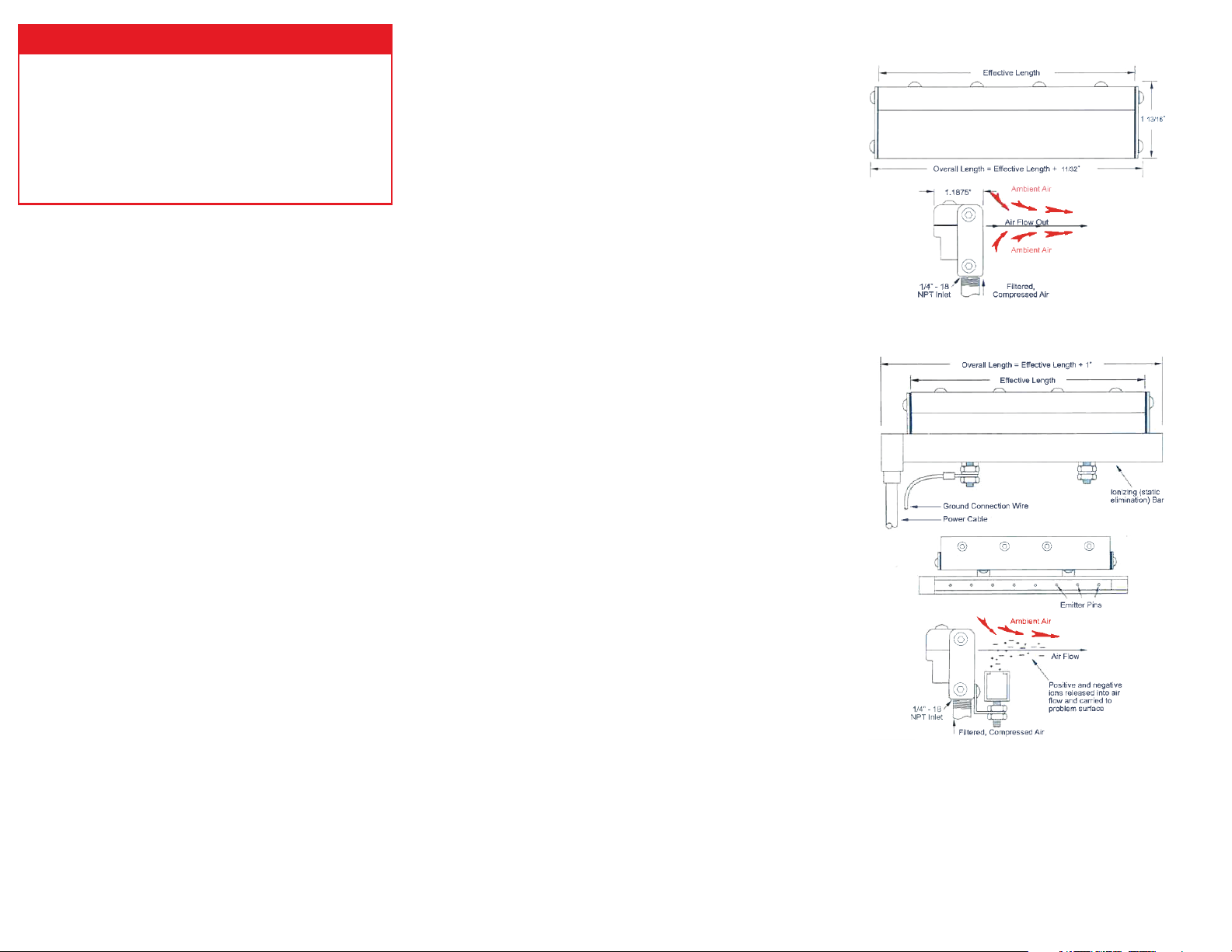
AIR KNIFE DIMENSIONS AND FUNCTIONALITY
IONIZING AIR KNIFE
(Drawings shown above are not to scale)
LIMITED WARRANTY
Vortec compressed air products manufactured by ITW Air Management
will be replaced or repaired if found to be defective due to manufacture
defect within ten years from the date of invoice. Refer to our website
www.vortec.com for full warranty details and limitations. ITW Air
Management makes no specic warranty merchantability or warrant of
tness to a particular purpose.
 Loading...