

Vorsis AirAura User Manual

Digital Spectral Processor
Quick Start Guide
and
Short Form Manual
First Printing – May 2010
600 Industrial Drive, New Bern, North Carolina, USA 28562

This Page Intentionally Left Blank
3

Subject Page Number
Welcome to AirAura 4
The Vorsis Company Vision 5
General Information - Introduction 6
Processing Structure Overview 7
Installation 8
Rack Mounting Considerations 9
Installation Tips 10
Grounding 10
Surge Protection 10
UPS/Power Conditioning 10
Analog Audio Connections 10
Digital Audio Connections 10
Where to install AirAura 11
Analog Left/Right STL 11
Composite Analog STL 11
Analog ‘phone’ lines 12
Digital STL 12
EAS – US Emergency Alert System 13
PPM – Arbitron People Meter 13
Energizing AirAura 14
Rear Panel Connections 14
Audio Inputs 15
Audio Outputs
FM Audio Outputs 15
HD Audio Outputs 15
Headphones 16
Network Connections 16
Wired Ethernet 16
802.11G Wireless 16
General Purpose I/O 16
User Presets 17

Basic Setup 19
Rack Mounting 19
AC Power 19
Selecting the Active Audio Input 19
Adjusting Input Levels 19
Making Output Connections 20
Setting Output Levels 20
Selecting Presets 21
Using the Front Panel GUI to Adjust FM Sound 22
AGC Depth 22
Compression 22
Density 22
Low/Warm Equalization 23
Mid/High Equalization 23
FM Loudness 23
Using the Front Panel GUI to Adjust HD Sound 23
AGC Depth 22
Compression 22
Density 24
Low/Warm Equalization 24
Mid/High Equalization 24
HD Loudness 25
Saving a Preset 25
Preset Scheduler / Events 26
Setting up AirAura and GUI Lite to ‘talk’ 27
Network/LAN Connection 27
GUI IP Address 27
Hardware IP Address 28
Subnet Mask 28
Gateway 28
AirAura’s Front Panel Network Settings 28
Configuring the Remote GUI 28
Connecting without a LAN (Direct Connection) 29
Wireless Connection 30
AirAura/Internet Security Concerns 30

About DHCP and AirAura 31
AirAura Ports and Network Protocols 31
If UDP Doesn’t Work 31
Using GUI Lite 31
Input Menu 32
Input Source 32
Audio Input Signal Presence Indicators 32
Automatic Input Failover 32
Analog Gain 33
AES3 Digital Gain 33
L/R Balance 33
Pre-Emphasis
Output Menu 33
Analog Output Type 33
FM Digital Output 33
De-Emphasis 33
Pre-Delay 33
HD Digital Output 33
Phase Reverse 33
Left/Right Reverse 33
Diversity Delay 33
Special Analog Output Mode Note 34
Stereo Encoder Menu 34
MPX Process 34
MPX Processor Style 34
Lookahead Limiter 34
Soft Clipper 35
Hard Clipper 35
Stereo Pilot Injection 35
SCA 1 and SCA 2 Inputs 35
TX 1 and TX 2 Outputs 35
Presets Menu 36
Selecting a Preset 36
Saving a Preset 36
Preset Library Functions 37

System Menu 37
System Settings Change with Preset Takes 37
Metering Data over TCP/IP 37
Headphone Source 38
Input 38
Analog Input 38
AES Input 38
HD Output 38
FM Pre-Delay 38
FM Output 38
Headphone Volume Control 38
Status Indicators 39
Temp 39
Analog 39
AES 39
Remote Login 39
Setting System Time 40
Accessing Menu Options 40
View 40
Input 40
Output 40
St Encoder 40
Presets 40
System 40
Sound 40
About 40
Hardware 40
Devices 40
On-Line Mode 40
Event Scheduler 40
Login Password 40
Version 40
Update 40
Presets 41
Take 41
Save 41
Library 41

Analysis Menu 41
FFT Introduction 41
O-scope Introduction 41
E vs. F Introduction 41
3-D Plot Introduction 41
SDR Introduction 41
A-Clip Introduction 41
Using and interpreting the FFT 42
Using the O-Scope 42
Using and interpreting the E vs. F Display 42
Using and interpreting the 3-D Plot 43
Using and interpreting the SDR Display 43
Using interpreting the A-Clip Display 43

Appendix A
Default Wired Ethernet Configuration / Changing the Configuration
Appendix B
Default Wireless Ethernet Configuration / Changing the Configuration
Appendix C
General Specifications
Appendix D
Wireless Module Configuration, Approvals, and Miscellaneous Data
Appendix E
General Purpose Input/Output - GPIO

- Welcome to AirAura -
The Audio Processing ‘Game Changer’
In the fall of 2007 we set an aggressive goal to design a new FM peak clipper.
Our goal was to find ways to better handle the challenges posed by competitive
loudness and the FM pre-emphasis curve without the audible aliasing, unnatural
high frequency loss, and intermodulation distortion side effects encountered with
conventional clippers. Little did we know that we would be working on our new
FM peak clipper for almost three years before our lofty goals were met to our
satisfaction.
Our new clipper (project code name “AirAura”) is a completely new approach to
FM audio peak control. AirAura clipper’s algorithm has the resolution required to
be able to tell the difference between distortion and audio, and mitigate only the
audible distortion. Music or speech, our new clipper makes it effortless to be
competitively loud and clean at the same time.
The new clipper turned out to be powerful, but it also required enhanced DSP
hardware in order to run it. Therefore we decided to make an entirely new
hardware product around it, and the AirAura on-air processor was born. While we
were under the hood we also tweaked up our Vorsis Bass Management System
algorithm (creating VBMS-II), and also improved our well regarded Sweet Spot
Technology (SST).
VBMS-II effortlessly reveals and controls very deep and natural bass in program
material that contains such bass. However, VBMS is not a bass creator. Rather,
it’s an algorithm that artistically manages bass in a way that keeps it and the rest
of the audio spectrum clean and natural. To enhance the bass experience even
further, we outfitted VBMS-II with a new Bass Texture algorithm which allows
customization of the bass experience when listening on receivers with smaller,
bass-shy speakers.
Our SST algorithm has been well received by Vorsis customers in the broadcast
industry … even Public Radio stations. SST invisibly manages the behavior of
the five-band AGC as the incoming program density changes. Transitions
between today’s heavily mastered hits and material mastered in a more gentle
time are no longer ‘on-air speed bumps’. SST manages program density as
content changes to provide the listener with a smooth, consistent, easy to listen
to sound.
SST is so effective at invisibly managing the audio that Vorsis products
incorporating this feature have been installed in facilities playing everything from
the most blaring modern rock to the quiet solitude of public radio stations with
much more conservative material.
4

The Vorsis Vision
The Vorsis Audio Processing division of Wheatstone was created in 2005, and
for a single purpose — to “competently design new audio processing tools for the
broadcast industry that truly improve the sound of broadcasting.”
Wheatstone founder and owner Gary Snow had noticed how harsh and distorted
radio stations had become over the years as they chased each other in the
loudness game with existing audio processing products. Frustrated with that
sound and how it was destroying the listening enjoyment originally intended for
radio, he set a goal for Wheatstone as a company:
“Design new technology
that truly improve the sound of radio,
not further destroy it.”
Today the Vorsis development team is comprised of experts in digital signal
processing, professional audio, and product design. The team is led by broadcast
engineering veteran and audio processing expert Jeff Keith (who’s been
interested in audio processing for the better part of 40 years). As well as
designing new DSP algorithms and clever and easy to use user interfaces, he
guides the Vorsis team as they design new and revolutionary audio processing
products.
All of the design, manufacturing and testing of Vorsis audio processing products
is accomplished at Wheatstone’s Corporate Headquarters in New Bern, North
Carolina, USA. In its large, state of the art design and manufacturing facility
Wheatstone maintains 100% control over the quality of their product design and
its manufacturing. True to their goal of making only the highest quality products
Wheatstone utilizes no ‘contract’ or ‘offshore’ manufacturing.
Wheatstone’s obsessive control over the design and manufacturing of their
products ensures that every
same admired product quality that Wheatstone has delivered to its customers for
over thirty years.
Wheatstone’s line of competently designed and feature-rich Vorsis audio
processing products offers the broadcast industry high-quality products with the
superior audio performance and product reliability that Wheatstone is famous for.
Built to Wheatstone’s exacting product and audio quality standards Vorsis audio
processors are a perfect match for those who truly care about how their station
sounds.
customer receives the highest quality gear of the
audio processors
5

General Information
Introduction
The Vorsis AirAura is designed to exceed the expectations of customers who
want more loudness on the radio dial without incurring the usual artifacts that
usually accompany competitive loudness. This third generation full-featured and
top-of-the-line Vorsis audio processor expands on technologies previously
invented by the Vorsis design team as well as incorporating new ones.
The Vorsis design team approaches audio processing with an attitude of ‘quality
first’ and the processing algorithms in the AirAura processor are designed to
push the limits of what can be accomplished in an on-air processor into
completely new territory. Every algorithm is carefully analyzed though hundreds
of hours of critical listening with a wide range of program material to ensure that it
does exactly what it was designed to do - no more and no less.
Equipped with the tools necessary to create the on-air sound you’ve been
yearning for, AirAura’s audio clarity, on-the-dial power and presence, and the
accuracy of its sound are not found in any other audio processing product.
Period. Music sounds like it was meant to sound. Voices are rich and full with no
hint of unnatural coloration or distortion. Transitions between various program
elements are deftly handled with no trace of “processing” while corrections are
being made.
Further, instead of a customer being saddled with the inescapable sound
signature engrained in other brands of audio processors by their designers,
Vorsis products, including the new AirAura, have no
their own. The customer is completely free to use the pallet of tools in the AirAura
to create whatever on air sound he can dream of, from no hint of processing at
all, to wall of sound.
With an internal base sampling rate of 192 kHz (some sections operate as high
as 1½ megahertz!) and its 144dB internal dynamic range AirAura processes a
station’s audio with extreme precision. Twin front panel LCD screens and touchpad allow control of all system and processing setup parameters. Equipped with
the Vorsis GUI Lite right on the front panel, the sound of the AirAura’s Factory
Presets can be quickly customized as desired.
For even more control over processing parameters an optional full-control GUI
designed for processing experts and sporting every possible control can be
obtained by registering for it at http://www.VorsisProGUI.com
users can download a full-control GUI having all processing adjustment controls
available.
fixed sound coloration of
. Once registered,
6

Processing Structure Overview
The AirAura digital audio processor is designed to separately process the audio
for both conventional analog FM and digital HD radio signals. Sharing the fourband fully parametric equalizer and highly intelligent five-band AGC, the FM and
HD paths each have their own 31-band limiter sections followed by separate final
limiters of different styles optimized for their intended mediums.
Each 31-band limiter section operates much like the high-resolution filter banks
used in perceptual codecs that rely on critical band masking to hide their
operation from the human ear. Because of this technology, and unlike other
limiters with fewer bands, human psychoacoustics makes the operation of each
31-band limiter section essentially invisible to the ear.
The FM signal path is equipped with the new AirAura clipper as well as a lookahead limiter — useful for less aggressive program formats. A digitally perfect
stereo generator provides two multiplex composite stereo outputs and two SCA
inputs. The input connector for SCA-2 can be internally switched to convert it into
a 19 kHz stereo pilot Sync output for RDS applications requiring a separate 19
kHz synchronization signal.
The HD signal path is equipped with a smart look-ahead final limiter with
adjustable operating parameters that allow program density and peak control to
be adjusted as desired. The HD path’s digital and analog outputs may be
swapped left for right as well as phase reversed to accommodate a known bug in
HD radio hardware.
A collection of Factory presets makes a wide range of on air sounds available to
the user. These presets, in combination with the front panel’s GUI Lite controls,
allow the end user to create literally millions of different on-air sounds that are
completely different from what the factory presets provide.
A fully routable headphone monitoring path allows the audio in various parts of
the processing chain to be auditioned.
The System Menu of all GUI’s provides access to a flexible preset scheduling
utility that, along with having daily events, also has a long-form schedule. This
feature allows preset changes to occur on a particular date and time in the future.
This feature is useful for changing presets weeks or months after a preset was
prepared for a special event without having to edit the regular daily schedule to
accommodate the special preset.
GPI (General Purpose Inputs) provide easy access to preset changes via
external events such as contact closures and automation control. In addition the
AirAura is equipped with our ACI protocol which allows complete control of the
processor by a program automation system beyond just preset changes.
7
Installation
We know that you’re probably in a hurry to get on the air with your new AirAura. If
you have little technical expertise with audio processor fundamentals, the
following pages will get you up and running as quickly as possible without having
to know a lot of techie stuff.
If during installation or setup you find that you need assistance or advice, please
feel free to contact our technical support folks at (252) 638-7000 or write to
techsupport@vorsis.com.
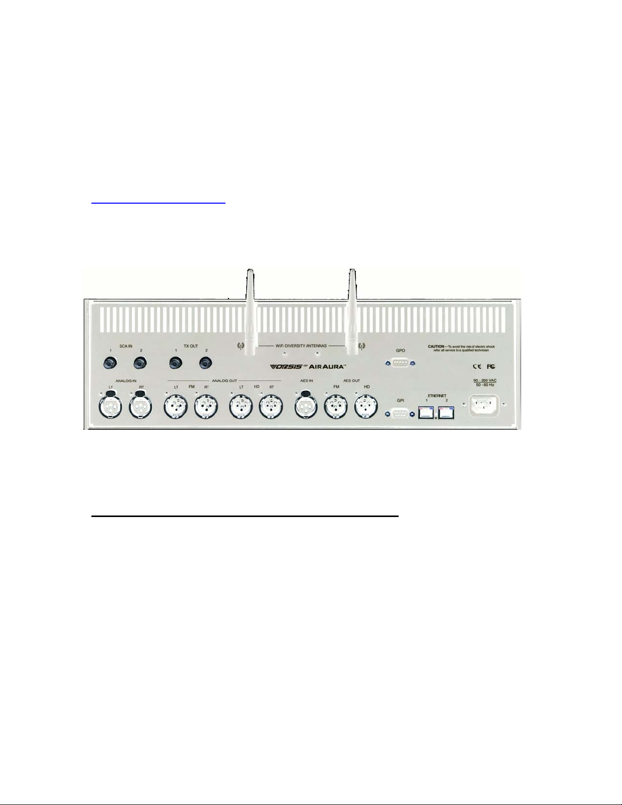
The image below (colors reversed to save on laser printer toner!) shows the rear
panel of the AirAura and the location of the various connectors associated with
an installation:
AirAura Rear Panel Connections
AirAura’s rear panel connectors from left to right are:
Bottom Row Top Row
Analog Left channel In SCA-1 Input
Analog Right Channel In SCA-2 Input
Analog Left Channel Out TX-1 Out
Analog Right Channel Out TX-2 Out
HD Analog Left Channel Out WiFi Antenna 1
HD Analog Right Channel Out WiFi Antenna 2
AES Digital Input GPO Output
FM AES Digital Out
HD AES Digital Out
GPI Input
Ethernet 1
Ethernet 2
AC Power Input
8

Rack Mounting
AirAura is designed to be mounted into an industry standard 19” equipment rack
and requires three rack units (5.25 inches / 13.335cm) of vertical space. If using
only two rack screws always use the bottom two to prevent twisting and other
undue forces from harming the processor.
AirAura does not have top or bottom cover vent holes. Rather, cooler air is drawn
into the unit through vertical slots positioned lower in the side panels, forcing
latent heat, which rises by natural convection, out through slots in the top of the
rear panel.
There is one small fan internal to the unit whose purpose is to stir air inside the
enclosure to even out the temperatures and prevent hot spots. The fan does not
‘remove’ heat and therefore failure of the 80,000 hour-rated fan, in the unlikely
event it should occur, will not compromise the operation of the AirAura as long as
AirAura is being operated in a reasonable environment (below 104F or 40C).
AirAura may be mounted between other devices in the equipment rack; however,
in accordance with good engineering practice it should not be mounted directly
above devices that generate significant amounts of heat such as power
amplifiers or power supplies. If such a location is unavoidable, then it is advisable
to utilize an extra 1RU blank rack panel between the AirAura and devices
immediately above and/or below it.
WARNING!
The AirAura enclosure normally does not need to be opened in the field.
Please be advised that the unit contains high voltage power supply circuits
that are hazardous and potentially deadly if accidentally contacted.
Because there are no user-serviceable parts inside the unit, it should be
returned to Wheatstone Corporation if repair becomes necessary.
9

AirAura Installation Tips:
• Grounding: Establish a lo w impedance common ground in your facility and try
to route all grounds to that point. AirAura’s ground reference (its chassis) should
be connected to the station ground. This is especially important in a high RF
environment.
• Surge protection: Place surge protection circuits as close as possible to the
AirAura being protected. Surge currents should be steered to power ground
instead of station ground if possible.
• UPS/Power Conditioning: Choose the best power conditioning/UPS units that
you can afford, focusing on the most important features and options that you
need. The better UPS products can prevent equipment damage and some even
come with an external equipment damage warranty.
• Analog Audio Connections: Balanced audio sources should be connected to
AirAura using shielded audio cable. Unbalanced audio connections, if they are
necessary, should be made with shielded two conductor cable such as Belden
8451 or 9451 as if connecting a balanced source. At the unbalanced source’s
output connect its “+ Output” to AirAura’s “Hi” (XLR pin2) input and connect the
unbalanced source’s shield wire to AirAura’s “Lo” (XLR pin-3) input wire. If the
cable shield is used (recommended) connect it to the AirAura end only (XLR pin
1) to prevent ground loops.
• Digital Audio Connections: For digital audio connections always use a good
quality digital audio cable with a characteristic impedance of 110 ohms. The
AES/EBU specification with its broad impedance tolerance allows for cables with
impedances from 88 ohms to 132 ohms - 110 ohms is ideal. Twisted pair cable
should be shielded, and in the case of multi-pair cable, each pair should be
individually shielded. Foil shielding is recommended for permanent installations.
Cable with a foil shield plus an overall braid should be used in applications where
frequent flexing of the cables may occur. Each cable pair is capable of carrying
two channels of AES3 digital audio.
Generic “audio” cable such as Belden 8451 and 9451 can be used for
interconnecting AES3 digital audio devices, but the wire length should be
minimized. The actual cable length that will work is primarily determined by the
error correction and jitter tolerance of the AES3 receiver device and the specific
cable used and its length.
The impedance of most ‘analog’ audio cables ranges from 40 ohms to 70 ohms
and represents a fairly large impedance mismatch from the nominal 110 ohms
required by the AES3 standard. Such impedance mismatch will result in signal
reflections which can cause bit errors and audio dropouts at the AES3 receiver.
10

The higher capacitance of generic analog cables slows down the rise time of the
digital data signals which can impair the ability of the AES3 receiver to accurately
detect digital signal transitions. This results in increased jitter, or at the extreme,
no audio at all.
Where to Install AirAura
The best location for installing AirAura, or any other “on-air” processor, is at the
transmitter site. However this requires that a discrete Left/Right STL, either
analog or digital, be involved in the signal path. The benefit of a transmitter site
installation is that it enables the use of AirAura’s built-in lab-grade stereo encoder
allowing more precise control of modulation peaks.
The transmitter site location also allows the operation of AirAura’s highly
oversampled composite clipper to be used to create an additional loudness
advantage. The Vorsis composite clipper algorithm is more forgiving than those
found in other products, and in combination with our pilot and SCA protection
filters can create additional loudness without the usual audio and spectral grunge
that composite clippers typically create.
We recommend that the processor (any processor) be interfaced to the
transmitter using the exciter’s composite stereo multiplex input. The exciter’s
AES3 digital input may be ‘clean’, but it also precludes the ability to gain
additional loudness through the use of AirAura’s intelligent oversampled
composite clipping. Depending on the sample rates being used the exciter’s AES
digital input can also exhibit somewhat inferior peak control than the composite
input.
If AirAura is located at the studio and an STL is used to send the program
material to the transmitter there are several issues that need to be considered.
Analog Left/Right STL:
Older analog discrete left/right STL’s can suffer from an inability to control audio
peaks because of inadequate bandwidth in their IF circuits or poor low frequency
performance. Individual STL’s rarely have identical audio group delay in both
channels which affects stereo separation when the signal is converted to the
multiplex composite domain. Such STL’s also usually suffer from AFC bounce
when handling processed low frequency material and that can rob modulation
capability.
Composite Analog STL;
An analog composite STL has several advantages over the analog left/right STL
just described. These STL’s typically have better audio performance than an
analog discrete STL, and most have the capability to piggyback subcarriers on
the composite audio. This means that most SCA and RDS generators can be
located at the studio end of the STL along with the audio processor. If nothing
11

else, this is at least a convenient setup. When a modern composite STL is used it
can be nearly as transparent audio-wise as a digital STL.
Analog Phone Lines:
We don’t recommend discrete left/right analog ‘phone line’ STL’s because of the
inability of many service providers to guarantee flat frequency response and
proper phase matching between the two circuits. Furthermore, in many countries
wideband analog circuits are unavailable or their cost is prohibitive.
On the other hand if the STL is a dedicated (and equalized if necessary) pair of
circuits under the station’s control then they may be acceptable.
Digital STL:
When using a Digital STL that employs audio compression, it is highly
recommended that the AirAura be placed at the transmitter site which puts it after
the codec. The reason for this placement is that the codec will usually sound
better when presented with unprocessed studio audio than when handling the
highly processed and pre-emphasized audio present at the processor’s output.
Further, the encoding schemes used in such STL’s will not accurately pass the
well-defined peak levels created by AirAura which will create a modulation
(loudness) disadvantage.
AirAura can also be installed at the studio end of a compressed STL with at least
two caveats:
- The stereo generator and composite clipper in AirAura are not available. Most
digital exciters offer a composite clipper function, but they are usually quite crude
in their implementation compared to AirAura’s exceptional clipper. “Exciter
hosted” composite clippers are never the optimum choice when the station’s
ultimate sound quality is important.
- Compressed (data reduced) STL’s do not perform well when presented with
competitively processed audio. This is because codecs work by examining the
audio for opportunities to remove something that shouldn’t be audible to the
human ear.
When dense audio is presented to a codec there are fewer ‘opportunities’ to
remove redundant audio information and mask it from our hearing. Under these
conditions codec operation can be much more obvious — even objectionable —
than when the processing is located after the codec where the masked artifacts
are only occasionally unmasked.
TIP: If using AirAura at the studio be certain that any clippers in the stereo
generator at the transmitter site are properly set up to complement the settings in
AirAura. This will prevent gross distortion and potentially large modulation
overshoots.
12

Also, pre-emphasis should always be applied by the audio processing, not the
exciter. Modern FM audio processors have special and quite complicated but
efficient circuits to deal with the challenges presented by the FM pre-emphasis
curve and can provide very tight modulation control with low perceived distortion.
FM exciters do not have this technology!
EAS – United States Emergency Alert System
If the EAS generator is placed before the AirAura, the levels of the signaling
tones and FSK data can be disturbed if the processing (any processing, not just
AirAura) is very aggressive. Therefore in this situation it is recommended that the
EAS encoder be placed after the processing.
If the EAS unit needs to be installed prior to AirAura and AirAura is operated
aggressively, AirAura may need to be configured so that when the EAS tones are
being sent AirAura is switched to a bypass mode or a less aggressive preset.
This can easily be accomplished by using AirAura’s GPI interface and by
assigning a special preset to the EAS function that has internal processing
defeated and audio levels calibrated to provide proper modulation levels during
EAS transmissions.
Arbitron People Meter (PPM)
Reports from the field indicate that AirAura favorably passes the data
watermarking scheme used in the Arbitron People Meter rating service
technology, regardless of the aggressiveness of the audio processing performed.
13

Energizing
Assuming AirAura is correctly rack mounted you may now energize it, noting that,
for long-term reliability reasons there is no power switch.
The AC line input voltage may be between 90 and 260 VAC, 50 or 60Hz. Power
consumption is under 100VA.
Aggressive AC input filtering is utilized at AirAura’s AC power input; however it is
always advisable to use some form of competent external surge protection
and/or an uninterruptible power supply (UPS), especially where AC power quality
is questionable, such as at a remote transmitter site.
Power conditioning, surge suppression, and even power backup devices are
wise investments when using sensitive modern electronic devices that, like
AirAura, use some type of internal computer.
The use of a UPS (uninterruptible power supply) is usually recommended and
will protect AirAura from short duration power interruptions which may otherwise
signal it to reboot when it sees the power glitch. When this happens there will be
a loss of audio for approximately 20 seconds.
Rear Panel Connections
All audio input and output, control, Ethernet, and power supply connections are
made via various connectors mounted on AirAura’s rear panel.
• Nine XLR connectors are provided for analog and digital audio
input and output connections.
• Four BNC connectors are provided for SCA in and TX (transmitter)
out connections.
• Two RJ-45 connectors are provided for Ethernet connections.
Either of these connectors can be used to connect a Windows® PC
running the Vorsis AirAura GUI.
• Two DB-9 connectors provide 8 GPI inputs (for selecting the first 8
presets) and four GPO outputs. The pin-out drawings in Appendix E
summarize wiring connections for these features.
14

Audio Inputs
Input audio can be applied to either the analog left/right inputs or to the AES3
digital input as appropriate. The AES3 input accepts sample rates between 32
kHz and 96 kHz.
Automatic audio failover from one input to the other is a user selectable option.
Automatic failover from AES3 to analog is instantaneous and based on invalid or
missing bits in the AES3 stream, or after 30 seconds of “silence” (level below 48dBFS).
Automatic failover from analog to AES3 is based on the same silence sense
algorithm responding to audio below -48dBFS for more than 30 seconds.
Audio Outputs
FM Audio Outputs
Output audio for the FM path is available as:
• Analog balanced left/right stereo.
• Analog balanced left/right stereo and de-emphasized according to
any pre-emphasis used.
• AES3 digital, either pre or post diversity delay, and/or deemphasized according to any pre-emphasis used.
• Balanced line level composite stereo.
• Unbalanced composite stereo on two rear panel BNC female
connectors.
HD Audio Outputs
Output audio for the HD path is available as:
• Balanced left/right analog.
• AES3 digital.
15
 Loading...