

VOPtel VG2020 User Manual

VG2020
Version: V1.6.80.20

Safety Notices
Please read the following safety notices before installing or using this gateway. They are crucial for the safe
and reliable operation of the device.
z
Please use the external power supply that is included in the package. Other power supplies may cause
damage to the gateway, affect the behavior or induce noise.
z
Before using the external power supply in the package, please check with home power voltage. Inaccurate
power voltage may cause fire and damage.
z
Please do not damage the power cord. If power cord or plug is impaired, do not use it, it may cause fire
or electric shock.
z
The plug-socket combination must be accessible at all times because it serves as the main disconnecting
device.
z
Do not drop, knock or shake it. Rough handling can break internal circuit boards.
z
Do not install the device in places where there is direct sunlight. Also do not put the device on carpets or
cushions. It may cause fire or breakdown.
z
Avoid exposure the gateway to high temperature, below 0℃ or high humidity. Avoid wetting the unit
with any liquid.
z
Do not attempt to open it. Non-expert handling of the device could damage it. Consult your authorized
dealer for help, or else it may cause fire, electric shock and breakdown.
z
Do not use harsh chemicals, cleaning solvents, or strong detergents to clean it. Wipe it with a soft cloth
that has been slightly dampened in a mild soap and water solution.
z
When lightning, do not touch power plug or gateway line, it may cause an electric shock.
z
Do not install this gateway in an ill-ventilated place.
z
You are in a situation that could cause bodily injury. Before you work on any equipment, be aware of the
hazards involved with electrical circuitry and be familiar with standard practices for preventing accidents.
2

Table of Content
1.Introducing VG2020 VoIP Gateway 4
1.1. Delivery Content 4
1.2. Pilot Lamp.................................................................................................................................. 4
1.3. Port of Connecting..................................................................................................................... 4
2.Initial connecting 6
2.1. Connect to network 6
2.2. Connect to Power ...................................................................................................................... 6
3. Basic Functions 7
3.1. Transferring a call..................................................................................................................... 7
3.2. Calling Hold and 3 ways call .................................................................................................... 7
4. Setting 8
4.1. Setting methods ......................................................................................................................... 8
4.2. Setting via Web Browse 8
4.3. Web page function explanation ................................................................................................ 9
4.3.1. Current Status ........................................................................................................................ 9
4.3.2. Network ................................................................................................................................. 10
4.3.2.1. WAN Config............................................................................................................. 10
4.3.2.2. LAN Config ...............................................................................................................11
4.3.3. VoIP ....................................................................................................................................... 12
4.3.3.1. SIP Config ................................................................................................................ 12
4.3.3.2. IAX2 Config ............................................................................................................. 14
4.3.4. Advance ................................................................................................................................. 15
4.3.4.1. DHCP Service .......................................................................................................... 15
4.3.4.2. NAT Configuration ................................................................................................. 16
4.3.4.3. Net Service................................................................................................................ 18
4.3.4.4. Firewall Config ........................................................................................................ 19
4.3.4.5. QoS Config ............................................................................................................... 20
4.3.4.6. Advance SIP Configuration .................................................................................... 22
4.3.4.7. Digital Map Configuration ..................................................................................... 24
4.3.4.8. Call Service .............................................................................................................. 25
4.3.4.9. MMI Filter ............................................................................................................... 26
4.3.4.10. DSP Config ............................................................................................................. 27
4.3.4.11. VPN Config ............................................................................................................ 27
4.3.5. Dial-Peer Setting................................................................................................................... 29
4.3.6. Config Manage...................................................................................................................... 31
4.3.6.1. Save Config .............................................................................................................. 31
4.3.6.2. Clear Config ............................................................................................................. 32
4.3.6.3. Backup Config ......................................................................................................... 32
4.3.7. Update ................................................................................................................................... 32
4.3.7.1. Web Update .............................................................................................................. 32
4.3.7.2. FTP/TFTP Update ................................................................................................... 33
4.3.7.3. Auto Provisioning .................................................................................................... 33
4.3.8. System Manage ..................................................................................................................... 34
4.3.8.1. Account Config ........................................................................................................ 34
4.3.8.2. Syslog Config............................................................................................................ 35
4.3.8.3. Time Config.............................................................................................................. 35
4.3.8.4. Logout &Reboot ...................................................................................................... 36
5. Appendix 37
5.1. Specification ............................................................................................................................. 37
5.1.1. Device specification .................................................................................................... 37
5.1.2. Voice Features............................................................................................................. 37
5.1.3. Network Features ....................................................................................................... 37
5.1.4. Maintenance and Management ................................................................................. 37
3

1. Introducing VG2020 VoIP Gateway
1.1. Delivery Content
Please check whether the delivery contains the following parts:
The gateway VG2020
The power supply
The Ethernet cable
The Telephone cable
User manual
1.2. Pilot Lamp
POWER Power Pilot La
m
p
The La
m
plig
ht, has electrified, can use VG2020
REG
Register station Pilot
La
m
p
Register succeed, the lamp light; register fail, the lamp flash; does not
re
g
ister,thelight off.
GATEWAY
Gateway work station
Pilot Lamp
Show is using VoIP service or PSTN service. Hang up, the light off;
when it is under the situation of VoIP, the lamp will light
after picking up the handset; If using PSTN, the light off.
WA N
WAN port Pilot Lamp
The Lamp light, WAN port connect to network; the lamp flash, there
are d
a
ta transferring.
LAN
LAN port Pilot Lamp
The Lamp light, LAN port connect to network; the lamp flash, there
are d
a
ta transferring.
1.3. Port of Connecting
POWER Power Port Output: 12VDC, 500mA.
LINE Lifeline Port Connect to PSTN line.
PHONE FXS Port Connect to Telephone or the enter line of
Switch.
LAN Network Port Connectitto PC
WAN Network Port Connect it to Network
4
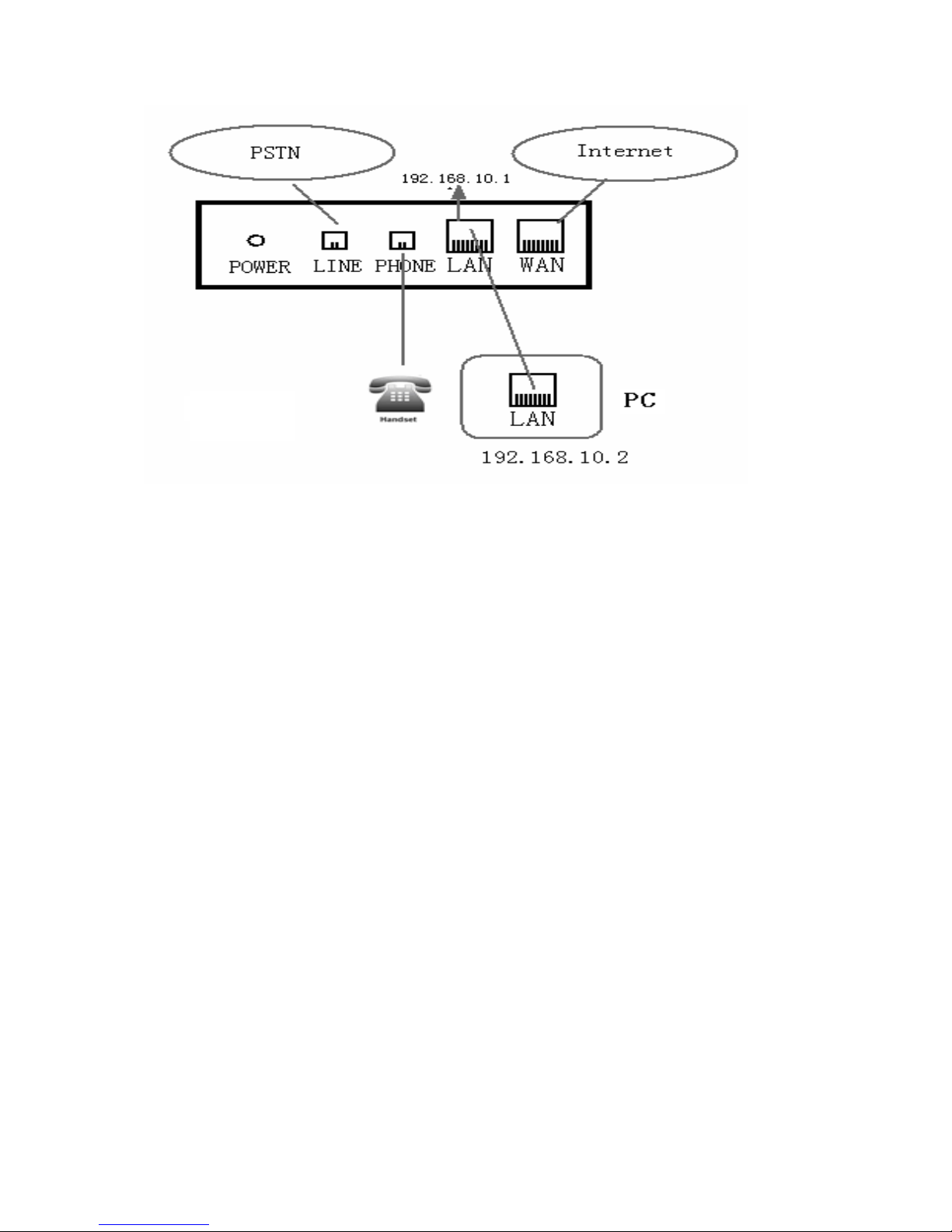
The gateway has two Network ports: The WAN port and the LAN port. Before you connect the power source,
please carefully read Safety Notices of this user manual.
5

2. Initial connecting
2.1. Connect to network
You can do this in one of two ways, depending on how your workspace is set up.
Direct network connection—by this method, you need at least one available Ethernet port in your workspace.
Use the Ethernet cable in the package to connect WAN port of your gateway to the Ethernet port in your
workspace. Since this gateway has router functionality, whether you have a broadband router or not, you can
make direct network connect.
Shared network connection—Use this method if you have a single Ethernet port in your workspace with your
desktop computer already connected to it. First, disconnect the Ethernet cable from the computer and attach it
to the WAN port on the back of your gateway. Next, use the Ethernet cable in the package to connect LAN
port of your gateway to your desktop computer. Your gateway now shares a network connection with your
computer.
2.2. Connect to Power
Connect the power supply plug to the DC 12V adapter port of the gateway. Use the power cable to connect
the power supply to a standard power outlet in your workspace.
If your VoIP gateway registers into corporate IP telephony Server, your gateway is ready to use.
6
3. Basic Functions
3.1. Transferring a call
Call transfer has several ways to realize:
◆
Blind transfer
When A talks to B, B may press the Flash key and * key and dial C gateway number, then press # key to
confirm, B hang up, and A will get through to C.
◆
Attended transfer
1. When A talks to B, B presses the Flash key, dial C gateway number and # key,After B talks to C, B could
hang up and A will get through to C.
2. When A talks to B,there is C call incoming to B; B may presses the Flash key to hold A,and talks to C,B
could hang up and C will get through to A.
Notice to VoIP Gateway Carrier: Your VoIP gateway server need support FRC3515, or else transferring can
not work.
3.2. Calling Hold and 3 ways call
There are two modes to enjoy hold function:
1. Press the Flash key during a call, and the call will be on hold. While a call is on hold, you can establish
another call by dialing your desired number and confirm it by the # button. Pressing the Flash key again
will resume the first call. By using hold function, you can talk with only one party; the other party who is
on hold can’t talk with you. If you press the * button, you will enter into 3 ways call.
2. If the third party calls you during a call, you can hear the voice of “du du”. Press the Flash key to hold the
first call, and then you can talk with the third party. By using hold function, you can talk with only one
party; the other party who is on hold can’t talk with you. If you press # key, gateway will hang up the first
call, and then accept the new incoming call.
Notice: You must enable the calling waiting or else calling hold can’t work.
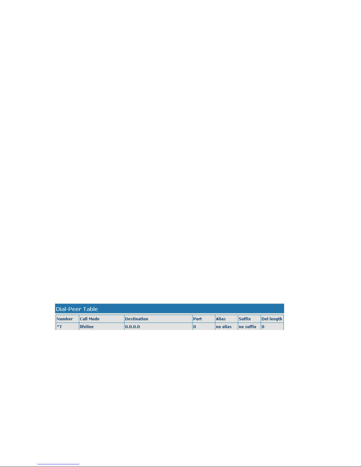
3.3. Communicate with PSTN user
The mapping of *T shows that user should dial * before the calling number when using PSTN line.
Of course you can setup others, not always use *T. (Must end with T)
The main function of Lifeline is: keep the gateway usable when power cut or network cut off.
When use Lifeline, should note as below:
● If the gateway through Lifeline, user can use it as a normal gateway
● User should insert the PSTN line to lifeline port before run the gateway. If you insert the PSTN line after
the gateway running, you will hear the voice of “pa pa ”, you can not use the lifeline at this time, you
should wait several seconds and hear the same voice of “pa pa ”, at this time, you can use the it
reassuring.
7

4. Setting
4.1. Setting methods
This VoIP gateway can be set via two different setting methods:
● The web browser on PC
● The terminal software
This Manual will tell you about the setting methods via the web browser on PC.
4.2. Setting via Web Browse
When this gateway and your PC are connected to your network, enter the IP address of the WAN port in this
gateway as the URL (e.g. http://xxx.xxx.xxx.xxx/ or http://xxx.xxx.xxx.xxx:xxxx/). If you do not know the
IP address, you can dial #*111 to get the IP address.
After you enter the IP address, you will see the following web interface.
This gateway provides different two privileges for different users to set it.
The two privileges are guest and administrator respectively. In guest privilege, user can see but not modify
Register/Proxy Sever Address and port of SIP, advance SIP and Iax2. In administrator privilege, user can see
and modify all setting parameters.
Default value in guest privilege
Username: guest
Password: guest
Default value in Administrator privilege
Username: admin
Password: admin
Input username and password, click “logon”, and you will enter setting web interface.
8
4.3. Web page function explanation
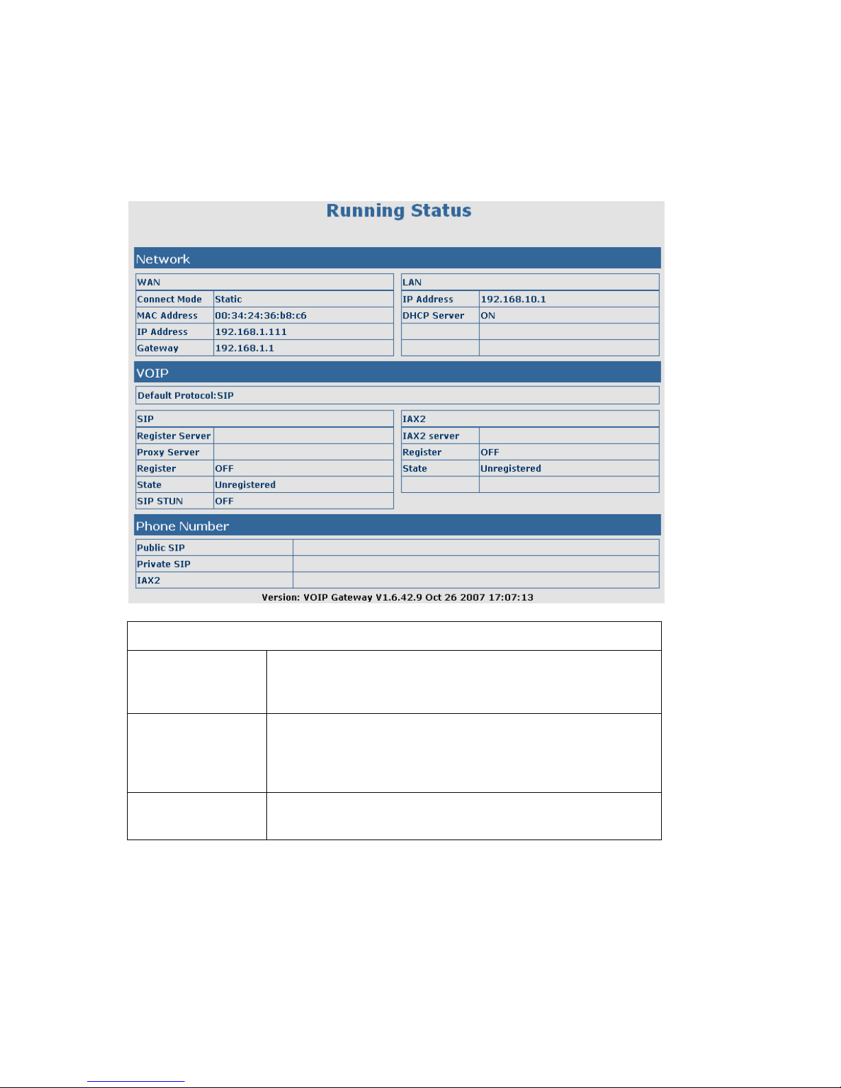
4.3.1. Current Status
Click on the first submenu “Current status”, you will enter in the following web interface. In this web interface,
you will see current set parameters, status, and the firmware version.
Current Status
Network
Shows the configuration information on WAN and LAN
port, including the connect mode of WAN port (Static, DHCP,
PPPoE), MAC address, the IP address of WAN port and LAN port,
ON o
r
OFF of DHCPmode of LAN port.
VoIP
Shows the current protocols of the gateway, and some parameters of
every protocol. You can know about IP addresses of register servers
of both IAX2 and SIP, proxy server IP address, whether start to
register the SIP and IAX2 servers or not, whether be registered or
un
reg
istered, and whether start to registerthe STUN server.
Gateway Number
Shows the gateway numbers provided by the SIP, SIP2 and IAX2
servers.
The last line shows the version nu
m
ber
and issued date.
9
4.3.2. Network
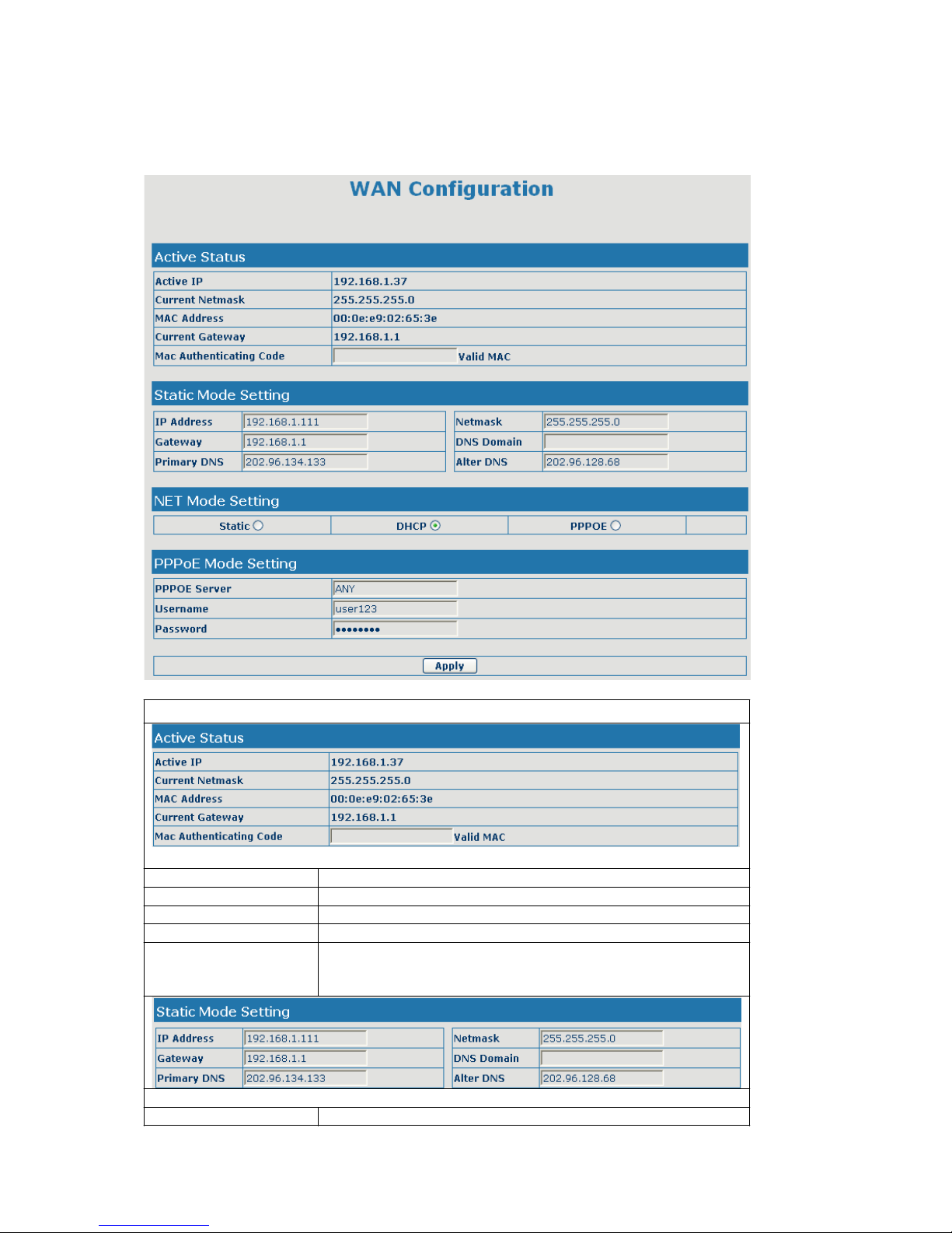
4.3.2.1. WAN Config
WAN Config
Active IP The current IP address of the gateway
Current Netmask The current Netmask address
MAC Address The current MAC address of the gateway
Current Gateway The current Gateway IP address
Mac Authenticating
Code
Set the corresponding authenticating code of MAC. If you don’t
pass the authentication, then it will show “invalid MAC”, at this
time, gateway will Hear the busy tone while the network is normal.
If you use static mode, you need set it.
IP Address Input the IP address distributed to you.
10
Netmask Input the Netmask distributed to you.
Gateway Input the Gateway address distributed to you.
Set DNS domain postfix. When the domain which you input can
DNS Domain
not be parsed, gateway will automatically add this domain to the
end of the domain which you input before and parse it again.
Primary DNS Input your primary DNS server address.
Alter DNS Input your standby DNS server address.
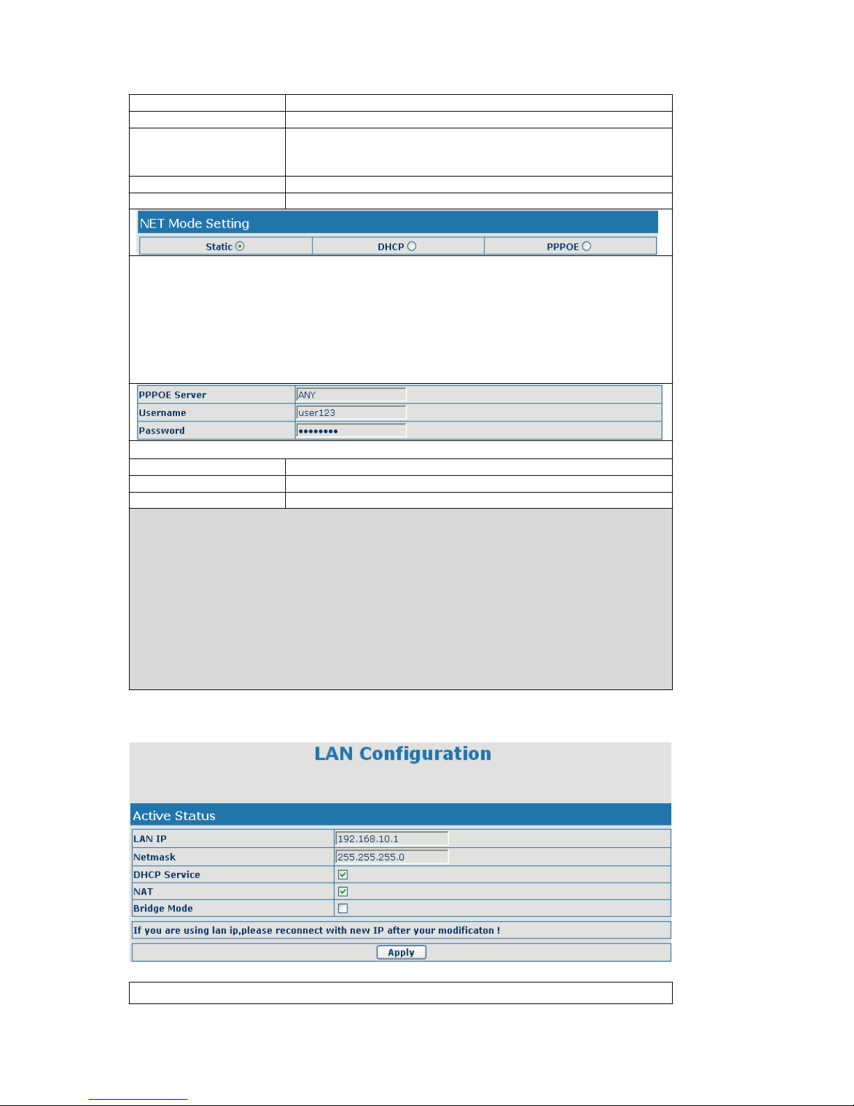
Please select the proper network mode according to the network condition. this VoIP Gateway
provide three different network settings:
z
Static: If your ISP server provides you the static IP address, please select this mode, and
then finish Static Mode setting. If you don’t know about parameters of Static Mode setting,
please ask your ISP for them.
z
DHCP: In this mode, you will get the information from the DHCP server automatically;
need not to input this information artificially.
z
PPPoE: In this mode, your must input your ADSL account and password.
If you uses PPPoE mode, you need to make the above setting.
PPPoE Server It will be provided by ISP.
User Input your ADSL account.
Password Input your ADSL password.
Notice:
1)Click “Apply” button after finished your setting, IP Gateway will save the setting
automatically and new setting will take effect.
2)If you modify the IP address, the web will not response by the old IP address. Your need
input new IP address in the address column to logon in the gateway.
3)If networks ID which is distributed by DHCP server is the same as network ID which is used
by LAN of system, system will use the DHCP IP to set WAN, and modify LAN’s networks
ID(for example, system will change LAN IP from 192.168.10.1 to 192.168.11.1) when
system uses DHCP client to get IP in startup; if system uses DHCP client to get IP in
running status and network ID is also same as LAN’s, system will refuse to accept the IP to
configure WAN. So WAN’s active IP will be 0.0.0.0
4.3.2.2. LAN Config
LAN Configuration
11
LAN IP specify LAN static IP
Netmask specify LAN Netmask
DHCP Service
Select the DHCP server of LAN port or not. After you modify the
LAN IP address, gateway will amend and adjust the DHCP Lease
Table and save the result amended automatically according to the
IP address and Netmask. You need restart the gateway and the
DHCP server setting will take effect.
NAT Select NAT ornot
Bridge Mode
Select Bridge Mode or not: If you select Bridge Mode, the
gateway will no longer set IP address for LAN physical port,LAN
and WAN will join in the same network. Click “Apply”, the gateway
will reboot.
Notice: If you choose thebridge mode, the LAN configuration will be dis
a
b
led.
4.3.3. VoIP
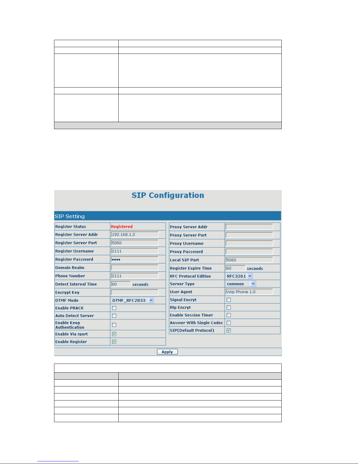
4.3.3.1. SIP Config
Set your SIP server in the following interface
SIP Confi
g
Filed name Illumination
Register Status Shows if thegateway has been registered the SIP server or not.
Register Server Add
r
Input
y
our SIP serveraddress.
Register Server Port Set your SIP server port.
Register Username Input your SIP registe
r
a
ccount name.
Register Password Input your SIP register password.
Proxy Server Addr
Set proxy server IP address (Usually, Register SIP Server
12
 Loading...