

Page 1
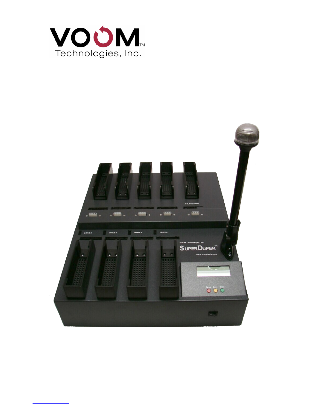
Voom SuperDuper™
User Guide
1-to-8 Hard Drive Duplicating Unit
Page 2
SuperDuper™ User Guide
SuperDuper is a registered trademark of Voom Technologies, Inc.
All other brand names, product names, and company names in this document
are trademarks or registered trademarks of their owners.
Third Edition
9 July 2013
(Based on the SuperDuper 2-01 release)
NOTICE OF PROPRIETARY RIGHTS
The equipment described herein including hardware, firmware, and
software is manufactured from designs that are the property of Voom
Technologies, Inc.
Reproduction or reverse engineering of any part of this equipment
without express written permission of Voom Technologies, Inc. is
prohibited.
Copyright © 2004-2013 Voom Technologies, Inc.
All Rights Reserved
Printed in U.S.A.
SuperDuper is designed, developed, and manufactured in the USA.
VOOM Technologies, Inc.
110 St. Croix Trail South
Lakeland, Minnesota 55043
Telephone 651-998-1618
Fax 651-436-4030
Page 3

Voom Technologies, Inc. © 2007-2013 Proprietary www.voomtech.com
Table of Contents
1 Information.........................................................................................1
1.1 Technical Documentation...........................................................................1
1.2 Data Protection............................................................................................ 1
2 Technical Support.............................................................................1
2.1 Support by Telephone.................................................................................1
2.2 Support by E-Mail........................................................................................ 1
2.3 Technical Support Tips...............................................................................1
3 Preface...............................................................................................2
3.1 Product Contents.........................................................................................2
3.2 Requirements............................................................................................... 2
3.3 Introduction..................................................................................................2
3.3.1 Features......................................................................................................................2
3.3.2 Standard Features......................................................................................................3
3.3.3 User Interface.............................................................................................................3
3.3.4 SHA-256 Hash Algorithm...........................................................................................5
3.3.5 Host Protected Area...................................................................................................5
3.3.6 Device Configuration Overlay...................................................................................5
3.4 Definitions.................................................................................................... 6
4 System Configuration.......................................................................7
4.1 Installing Source Drive................................................................................7
4.2 Installing Target Drives............................................................................... 8
5 Command Description......................................................................9
5.1 System Test Command...............................................................................9
5.2 Clone Drive Command................................................................................9
5.3 Verify Drives Command............................................................................10
5.4 Wipe Drives Command..............................................................................10
5.5 Remove HPA Command............................................................................10
5.6 Remove DCO Command...........................................................................10
6 Button Interface...............................................................................11
6.1 Reset Alarm Procedure.............................................................................12
6.1.1 Alarm Buzzer (Warning)..........................................................................................12
6.1.2 Fast Blinking Light (Error).......................................................................................12
6.1.3 Slow Blinking Light (Error)......................................................................................12
6.1.4 Steady Light (Done).................................................................................................12
6.2 System Test Procedure.............................................................................13
6.3 Clone Drive Procedure..............................................................................13
6.4 Verify Drives Procedure............................................................................14
Page 4

Voom Technologies, Inc. © 2007-2013 Proprietary www.voomtech.com
6.5 Wipe Drives Procedure..............................................................................14
6.6 Remove HPA Procedure............................................................................15
6.7 Remove DCO Procedure...........................................................................16
7 Serial Interface.................................................................................17
7.1 System Test Procedure.............................................................................18
7.2 Clone Drive Procedure..............................................................................18
7.3 Verify Drives Procedure............................................................................19
7.4 Wipe Drives Procedure..............................................................................20
7.5 Remove HPA Procedure............................................................................20
7.6 Remove DCO Procedure...........................................................................21
8 Special Precautions........................................................................22
8.1 Using the Buttons......................................................................................22
8.2 Target Drive Size Limitations.................................................................... 22
9 Troubleshooting..............................................................................23
10 Warranty......................................................................................... 25
10.1 Limited Warranty......................................................................................25
10.1.1 Wearable Parts.......................................................................................................26
10.2 Warranty Return Instructions.................................................................26
11 Specifications................................................................................27
11.1 CE.............................................................................................................. 27
11.2 FCC Exemption........................................................................................ 27
Page 5

Voom Technologies, Inc. © 2007-2013 Proprietary www.voomtech.com
1 Information
1.1 Technical Documentation
Specifications and information contained in this manual are furnished by Voom
Technologies, Inc. for informational use only and are subject to change at any
time without notice and should not be construed as a commitment by Voom
Technologies, Inc. Voom Technologies, Inc. assumes no responsibility or liability
for any errors or inaccuracies that may appear in this manual; including the
products, firmware and included accessories.
1.2 Data Protection
The user must be aware that an improper system configuration can lead to data
corruption. Please read the System Configuration chapter carefully before
attempting to operate this device. Voom Technologies, Inc. is not responsible for
any loss of data resulting from the use, disuse or misuse of this product.
2 Technical Support
2.1 Support by Telephone
Technical support is available to registered owners of Voom Technologies, Inc.
products by telephone Monday through Friday 8:00am to 4:00pm, Central Time
Zone at 651-998-1618.
2.2 Support by E-Mail
Voom Technologies, Inc. technical support is available by e-mail at
2.3 Technical Support Tips
Call from a telephone where you have access to your computer. Please be
prepared to provide the following information:
● Name, telephone number, e-mail address
● Serial Number and version of the Voom SuperDuper product
● Make and model of your hard drives
● Symptoms of the problem
1
Page 6

Voom Technologies, Inc. © 2007-2013 Proprietary www.voomtech.com
3 Preface
3.1 Product Contents
SuperDuper Hard Drive Duplicating Unit
8 inch SATA cables (9 shipped)
8 inch ATA ribbon cables (9 shipped)
Molex to SATA power adapters (2 shipped)
Molex to Molex Y power cables (4 shipped)
Molex to SATA Y power cables (4 shipped)
Molex to Molex 6 inch extension cable
Molex to SATA 6 inch extension cable
Standard serial interface cable
AC power cord
User Guide
3.2 Requirements
The SuperDuper Hard Drive Duplicating Unit supports parallel ATA and SATA
hard drives.
3.3 Introduction
The SuperDuper Hard Drive Duplicating Unit is designed to simultaneously copy
information from an external source drive to each of the 8 destination (target)
drives attached. It provides physical connections for both parallel and serial
drives. The architecture also provides a separate data bus for each drive, 9 in
all. This multiple bus architecture allows the hardware to transfer data directly
from the source drive to each of the target drives without the need for any
software buffering, resulting in the fastest data transfer possible. The primary
operations that are supported include the following:
● Clone Drive – Performs a sector-by-sector copy of the entire source drive to
each of the target drives.
● Verify Drives – Performs a sector-by-sector verify of the data stored on each
of the target drives.
● Wipe Drives – Writes an all zeros data pattern to each of the target drives.
3.3.1 Features
The SuperDuper product is designed to operate with drives (up to 2TB) that
support either 28 or 48 bit addressing and both PIO and UDMA data transfer
modes. In addition, it automatically detects the drive type (ATA/SATA) and the
drive address (Master/Slave) for both the source and each of the 8 target drives.
2
Page 7

Voom Technologies, Inc. © 2007-2013 Proprietary www.voomtech.com
3.3.2 Standard Features
The SuperDuper product supports the following features:
● Automatically discovers the source drive (ATA/SATA).
● Automatically discovers up to a maximum of 8 target drives (ATA/SATA).
● Automatically configures itself for the smallest size target drive.
● Automatically configures itself for the lowest speed target drive.
● Provides both a Button Control Panel and a Serial Port interface.
● Provides the ability to simultaneous transfer data from the source drive to
each of the 8 target drives with no performance degradation.
● Displays the operating status and drive state to a 4 line LCD display.
● Indicates the current operating status using both a status light and buzzer.
● Deactivates a failing target drive without interrupting the other drives.
● Automatically senses the presence of a HPA/DCO on each of the drives.
● Clones the source drive by doing a sector-by-sector copy of the entire
source drive to each of the target drives simultaneously. In addition, it
calculates a SHA-256 hash on the contents of the source drive which can
later be used to verify the data on each of the target drives.
● Verifies that the data has been transferred correctly by simultaneously
calculating a SHA-256 hash on all drives and comparing the resulting hash
value of each target drive with the hash value of the source drive.
● Writes an all zeros data pattern to each of the target drives simultaneously.
3.3.3 User Interface
The user interface for the SuperDuper Hard Drive Duplicating Unit supports both
a LCD (4 line x 20 character) and a serial port. Input is taken through either a
button control panel or a keyboard via a terminal connected to the serial port.
The status information is always displayed to both the LCD and the serial
terminal when connected The following is displayed on the LCD:
● The SuperDuper software version
● The operating state (e.g., Initializing, Ready, Busy, etc.)
● The number of bytes that have been written
● A list of drives, both Active and Disabled
The SuperDuper is designed to disable a target drive whenever a write error is
encountered. Disabling a failing drive does not effect any of the other target
drives and the operation will continue. Whenever a target drive is deactivated,
the failing drive is added to the failed drive list (e.g., Drives: 1234568 F: 7
indicates that drive 7 has failed) which is displayed on the LCD. In addition, the
buzzer will sound each time the light mounted on the unit blinks, to indicate that a
drive has failed. If all of the drives are deactivated, the LCD will indicate that all
drives have failed and the status light will blink fast .
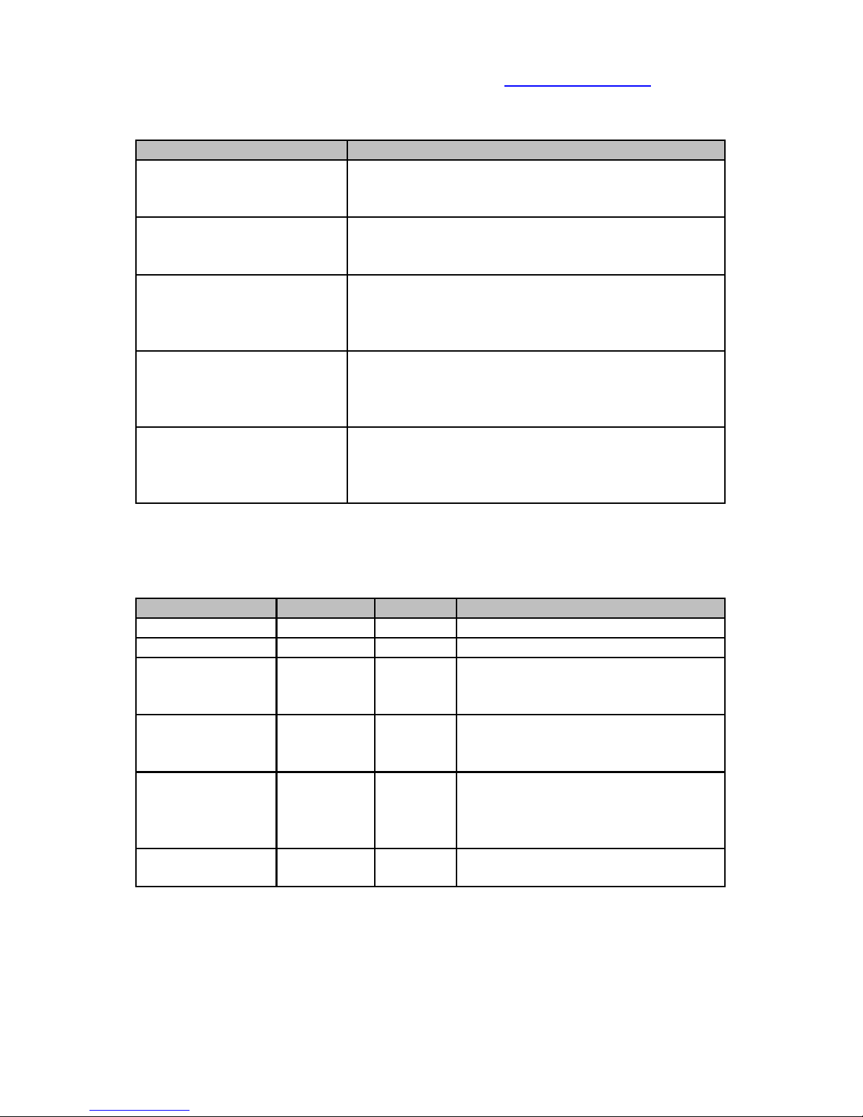
The following table illustrates the status conditions that will be displayed on the
LCD following the execution of each command:
3
Page 8
Voom Technologies, Inc. © 2007-2013 Proprietary www.voomtech.com
LCD Status Description
SuperDuper 2-01
Status: Ready
Drives: 12345678
Normal completion status.
All drives are still enabled.
SuperDuper 2-01
Status: Ready
Drives: 123678 F:45
Abnormal completion status.
Drives 4 and 5 failed the previous operation.
SuperDuper 2-01
Status: Ready
Drives: 12345678
<No Source Drive>
Abnormal completion status.
The Source drive has failed.
SuperDuper 2-01
Status: Ready
Drives: F:12345678
<No Target Drive>
Abnormal completion status.
All Target drives have failed.
SuperDuper 2-01
Status: Ready
Drives: F:12345678
<No Active Drive>
Abnormal completion status.
All Target drives have failed.
The status indicators are designed to communicate the basic operating status to
an operator who is located a distance from the unit. It currently provides the
following status information:
System Status Light Buzzer Description
Ready Off Off Unit is accepting commands
Executing Heartbeat Off Unit is executing last command
Drive Failure
(Running)
Heartbeat Beep Unit has disable one or more
target drives and is continuing to
execute the last command
Drive Failure
(Finished)
Flashing
(1/sec)
Off Unit has completed the command
with one or more target drive
failures.
All Drives Failed
(Finished)
Flashing
(2/sec)
Off Unit has terminated execution due
to an unrecoverable error. Either
the Source drive failed or all the
Target drives have failed.
Finished On Off Unit has completed the command
successfully.
Note: Refer to the Reset Alarm Procedure section for details on how to
reset the alarm buzzer whenever it is beeping.
4
Page 9

Voom Technologies, Inc. © 2007-2013 Proprietary www.voomtech.com
3.3.4 SHA-256 Hash Algorithm
The SHA-256 is a cryptographic hash function designed by the National Security
Agency (NSA). SHA is an abbreviation for Secure Hash Algorithm. Regarding
the SuperDuper unit, this hash value can be thought of as a “digital fingerprint” of
the data contained on a specific drive. The SHA is used to verify that multiple
drives contain identical information.
3.3.5 Host Protected Area
The Host Protected Area (HPA) feature provides a method for hiding data on a
disk drive. The SuperDuper Hard Drive Duplicating Unit will recognize the
presence of data hidden by a HPA on the source drive and automatically copy
both the configuration itself along with the associated data to each of the target
drives. It will also recognize the presence of a HPA configuration on each of the
target drives and automatically remove it.
Note: Because of the way that the HPA feature works, a power cycle (e.g.,
Powering off the SuperDuper unit) may be required whenever managing
data hidden by a HPA.
3.3.6 Device Configuration Overlay
The Device Configuration Overlay (DCO) feature set provides yet another way to
hide data on a disk drive. The SuperDuper Hard Drive Duplicating Unit will
recognize the presence of data hidden by a DCO on the source drive and
automatically copy both the configuration information itself along with the
associated data to each of the target drives. It will also recognize the presence
of a DCO configuration on each of the target drives and automatically remove it.
Note: Because of the way that the DCO feature works, an unexpected
power interruption (e.g., switching the SuperDuper unit off while executing
a data transfer command) will result in the loss of the DCO configuration
on the source drive. Therefore, make sure that you always allow the clone
to finish or Cancel the clone prior to powering off the SuperDuper unit.
5
Page 10

Voom Technologies, Inc. © 2007-2013 Proprietary www.voomtech.com
3.4 Definitions
ATA: Advanced Technology Attachment interface.
Parallel ATA Drive: An ATA hard drive whose data interface uses a 40 pin (40
or 80 conductor) ribbon cable.
Serial ATA Drive: An ATA hard drive whose data interface uses a 7 pin cable.
Source Drive: The hard drive from which the source data is read from during a
copy operation.
Target Drive: One of 8 hard drives that the data is written to during either a
copy or wipe operation.
Clone: The process of performing a sector-by-sector copy operation from the
source drive to each of the target drives.
Wipe: The process of writing zeros to every sector of the target drives.
SHA Hash: The value that is generated by calculating a SHA-256 hash on every
sector of a drive.
Host Protected Area (HPA): A reserved area for data storage outside the
normal operating file system.
Device Configuration Overlay (DCO): A virtual device configuration for the
hard drive which may change the drive size and/or other properties.
Ctrl: The keyboard control key.
HD or HDD: Hard Drive, also called the Hard Disk Drive.
GB: Gigabyte: 1000000000 bytes.
MB: Megabyte: 1000000 bytes.
KB: Kilobyte. 1024 bytes.
6
Page 11

Voom Technologies, Inc. © 2007-2013 Proprietary www.voomtech.com
4 System Configuration
This chapter describes how to configure the SuperDuper unit to copy information
from a single source drive to 8 target drives.
4.1 Installing Source Drive
The SuperDuper can accommodate either a parallel ATA or serial ATA source
drive. A parallel drive will be connected using an ATA ribbon cable, while a serial
drive will be connected using a SATA cable. In both cases, the drive must be
connected directly to the SuperDuper unit (e.g. Source Drive receptacle). Power
for the drive is available from the power strip located in the center of the unit. All
parallel drives and some SATA drives can use the Molex power connectors
provided; however, SATA power adapters should be used for any SATA drive
equipped with the SATA power port. Do not connect 2 power cables to one
drive. Please use the following steps to install the source drive:
1. Power off the SuperDuper unit.
2. Attach the source drive to the power strip using either the Molex or SATA
extension cables provided.
3. For SATA drives, connect one end of the SATA cable to the SuperDuper unit
and the other end to the source drive.
4. For parallel ATA drives, first attach the blue connector of the ATA ribbon
cable to the rectangular port on the SuperDuper unit that correlates with the
source drive (e.g. Source Drive receptacle). Then, attach the black
connector of the ATA ribbon cable to the rectangular port on the source drive
itself.
Caution: Due to the design of both the SATA power and data connectors,
please ensure that each of the SATA cables are installed properly with no
sideways pressure on either end of the cables.
7
Page 12

Voom Technologies, Inc. © 2007-2013 Proprietary www.voomtech.com
4.2 Installing Target Drives
One or more target drives, up to a maximum of 8, can be connected to the
SuperDuper unit. It can accommodate a combination of both parallel ATA and
SATA drives installed in any arrangement. Each of the parallel drives will be
connected using an ATA ribbon cable, while each of the serial drives will be
connected using a SATA cable. Power for each of the drives is available from
the power strip located in the center of the unit. Please follow the steps
described below to install the target drives:
1. Power off the SuperDuper unit.
2. Attach each of the target drives to the power strip using either the Molex to
Molex or Molex to SATA cables provided.
3. For serial ATA drives, connect one end of the SATA cable to the
SuperDuper unit and the other end to the corresponding target drive.
4. For parallel ATA drives, first attach the blue connector of the ATA ribbon
cable to the rectangular port on the SuperDuper unit. Then, attach the black
connector of the ATA ribbon cable to the rectangular port on the
corresponding target drive itself.
Caution: Due to the design of the SATA power and data connectors, please
ensure that each of the SATA cables are installed properly with no
sideways pressure on either end of the cables.
8
Page 13

Voom Technologies, Inc. © 2007-2013 Proprietary www.voomtech.com
5 Command Description
This chapter provides a brief description of each of the commands supported by
the SuperDuper unit. Please refer to the Button Interface and Serial Interface
chapters of this document for detailed instructions on how to execute each of the
commands. Refer to the Troubleshooting chapter for information relating to a
failure.
5.1 System Test Command
This command is designed to verify that each of the the drives are connected
properly. The test scheduled by this command simply reads a fixed number of
sectors from the each of the target drives and discards the data.
Note: This test is non-destructive as no data is written to any of the drives.
5.2 Clone Drive Command
This command is used to duplicate the source drive to each of the target drives
installed. Clone performs a sector-by-sector copy from the source drive to each
of the target drives, which will result in one or more exact copies of the source
drive. However, each of the target drives must have a capacity which is either
equal to or greater than the capacity of the source drive itself. If the size of any
target drive is less than the size of the source drive, a failure message will be
displayed and the clone operation will terminate prematurely.
Optionally, this command can perform a verify operation after the clone operation
has finished. The verify operation ensures that all of the data contained on the
source drive was copied to each of the target drives successfully.
If a target drive is larger than the source drive, a portion of the target drive may
not be usable. In this case, the unused sectors of the larger target drive are
automatically wiped after the clone operation has completed.
The processing of either a Host Protected Area (HPA) or a Device Configuration
Overlay (DCO) is automatically handled by the SuperDuper Hard Drive
Duplicating Unit. If either a HPA or DCO exists on any of the target drives, it will
automatically be removed during the processing of the Clone operation.
However, if either a HPA or DCO exists on the source drive, the data contained
in the protected area of the source drive will be copied to each of the target
drives and the same HPA or DCO will be configured on each of the target drives
as well.
9
Page 14

Voom Technologies, Inc. © 2007-2013 Proprietary www.voomtech.com
5.3 Verify Drives Command
This command is used to verify that the information copied to each of the target
drives is identical to that of the source drive. Verify calculates a SHA-256 hash
on each of the target drives and verifies that each of the resulting values match
the hash value associated with the source drive. In addition, this command also
displays the actual SHA-256 value at the end of the verify operation so that it can
be referenced for future disk operations.
Note: This command will not verify the data stored in either a Host
Protected Area (HPA) or a Device Configuration Overlay (DCO), as
unlocking the hidden area of a drive once it has been duplicated could
jeopardize the data that is stored in the protected area.
5.4 Wipe Drives Command
This command is used to erase all of the data from each of the target drives
installed. It fills each of the sectors with a zero data pattern. If one of the target
drives is larger that another, the wipe operation will automatically continue until
each of the installed target drives is completely wiped, including the largest one
installed.
The processing of either a Host Protected Area (HPA) or a Device Configuration
Overlay (DCO) is automatically handled by the SuperDuper Hard Drive
Duplicating Unit. If either a HPA or DCO exists on any of the target drives, it will
automatically be removed during the processing of the Wipe operation.
5.5 Remove HPA Command
Older revisions of the ATA specification limit the configuration or removal of an
HPA to once per power cycle of the hard drive. To accommodate all hard drives
this command will instruct the user to power off the SuperDuper if it finds and
removes an HPA one or more of the target drives. HPAs are also automatically
removed prior to performing a Clone operation. If none of the target drives
contain a HPA, no power cycling will be required.
5.6 Remove DCO Command
This command is used remove the DCO from each of the target drives. Unlike
HPAs, DCOs can be reconfigured multiple times without power cycling a hard
drive. The SuperDuper unit will automatically reconfigure or remove DCOs while
processing a Clone or Wipe command.
10
Page 15
Voom Technologies, Inc. © 2007-2013 Proprietary www.voomtech.com
6 Button Interface
The button control panel and the LCD are designed to be the normal user
interface. The LCD is used to display each of the menu items, the current
operating state, the progress of the current command, and to acknowledge the
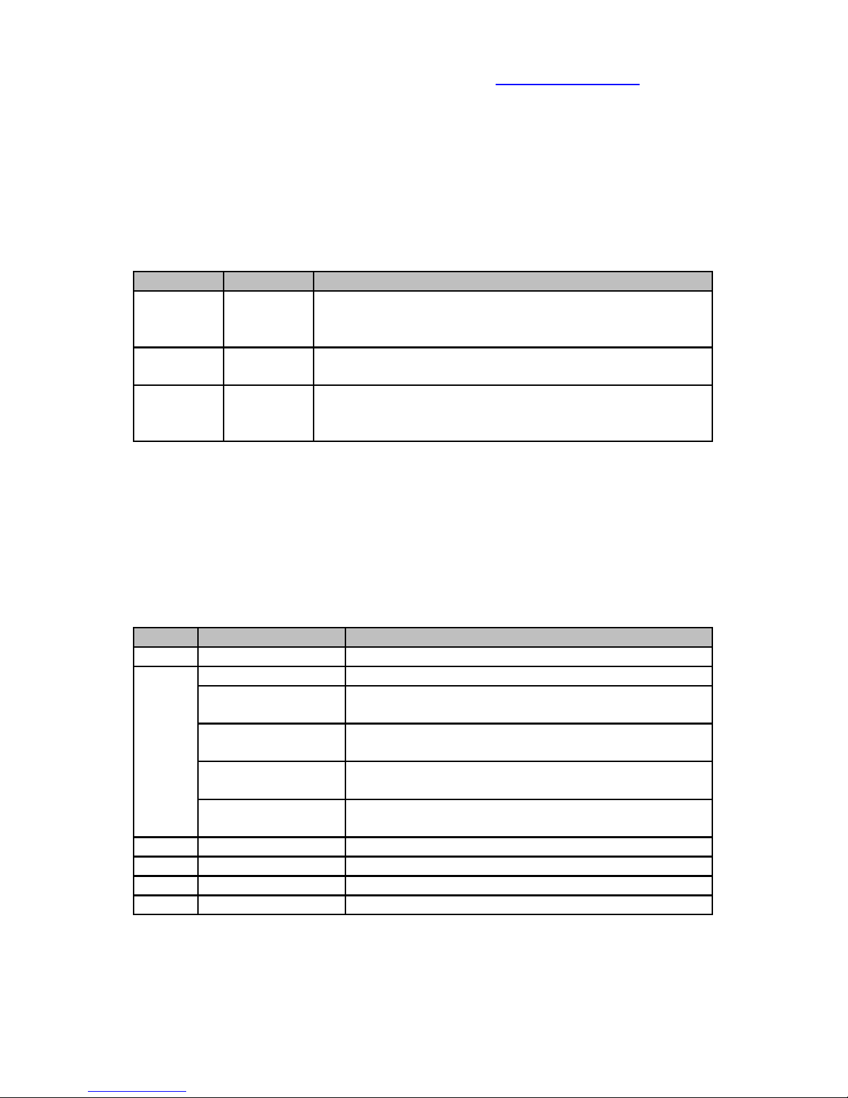
command status information. The button panel consists of the following three
buttons:
Button Function Description
Yellow Menu This button is designed to step through each of the
menu or parameter items. It always steps in a
forward direction.
Green Enter This button is designed to either select a menu or
parameter item, or acknowledge status information.
Red Cancel This button is designed to either abort the entering of
a new command or the execution of the previous
command.
The button command menu is organized into a series of levels and parameter
values. When displayed, the command information is displayed on the top line of
the LCD and the parameter information on the next line. The level information is
separated from the command information using a colon (e.g., [1:System Test]
refers to level 1, and a command of “System Test”). Each of the parameters
associated with a particular command (e.g., Wipe Enabled, Wipe Disabled) are
displayed under the command once it has been selected. The prompting
hierarchy used to organize the set of supported commands follows:
Level Prompt Description
1 System Test Perform a system test.
2 Clone Drive Perform a clone drive operation.
SHA Disabled Disables the verification of each target drive
after the clone operation has finished (default).
SHA Re-Verify Enables the verification of each target drive after
the clone operation has finished.
Wipe Enabled Enables wiping the unused area of a target drive
(default).
Wipe Disabled Disables wiping the unused area of a target
drive.
3 Verify Drives Verify all drives contain the same data.
4 Wipe Drives Perform a wipe drive operation.
5 Remove HPA Remove HPA from target drives.
6 Remove DCO Remove DCO from target drives.
Whenever commands are entered from the button control panel, all status
information must be acknowledged by the operator. A special arrow character
11
Page 16

Voom Technologies, Inc. © 2007-2013 Proprietary www.voomtech.com
[←] displayed in the lower right hand corner of the LCD indicates that the unit is
waiting for acknowledgment of the data currently displayed on the LCD. Press
the <enter> button each time the arrow character is displayed in order to
continue executing the current command.
Note: When operating from the button control panel, the user may
terminate an executing command by pressing the <cancel> button.
6.1 Reset Alarm Procedure
This section describes the sequence associated with clearing both the status
light and the alarm buzzer, once the operator has analyzed either a warning or
an error condition.
6.1.1 Alarm Buzzer (Warning)
A beeping sound heard while a data transfer operation is in process indicates
that one of the drives has failed, but that there is at least one active drive
remaining. To acknowledge this warning condition, momentarily press the
<cancel> button to reset alarm buzzer.
6.1.2 Fast Blinking Light (Error)
A fast blinking light indicates that all of the drives have failed and that all data
transfer operations have been suspended. Whenever this condition occurs,
power off the unit and ensure that each of the cables is securely attached to the
target drives. Once all of the cables are securely attached, power on the unit and
monitor the status of the Power On Self Test (POST).
Note: If any of the drives fail POST, please remove the failing drives before
issuing the next data transfer command.
6.1.3 Slow Blinking Light (Error)
A slow blinking light after the data transfer has completed indicates that one or
more target drives have failed; however, at least one target drive contains a
successful duplicate. Press the <enter> button to acknowledge this condition
and reset the light status.
6.1.4 Steady Light (Done)
A steady light indicates that the previous command has completed successfully.
Momentarily press the <enter> button to acknowledge this condition and reset
the light status.
12
Page 17
Voom Technologies, Inc. © 2007-2013 Proprietary www.voomtech.com
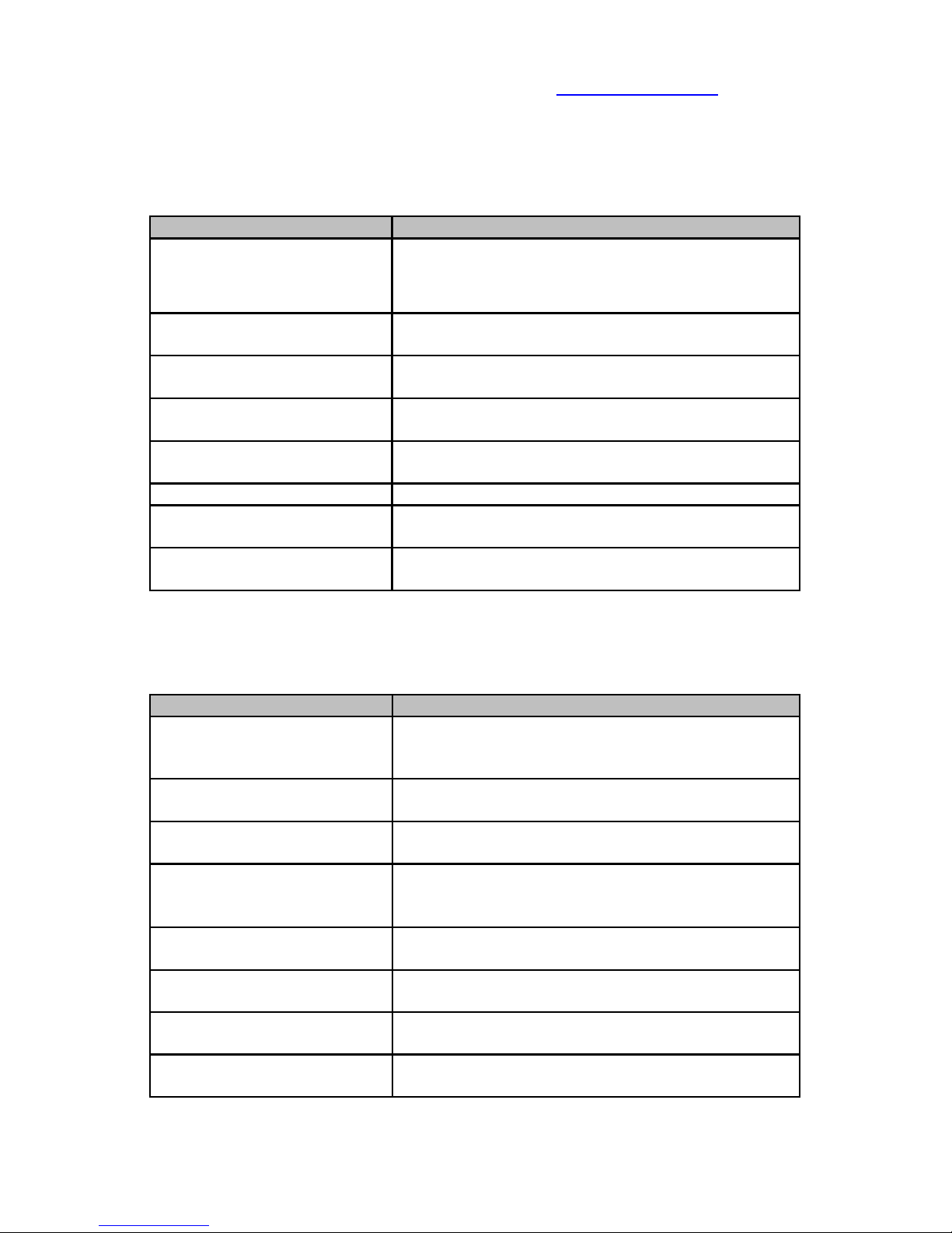
6.2 System Test Procedure
The following table describes the sequence associated with performing a system
test of the current configuration using the button panel interface.
LCD interface Comments
SuperDuper 2-01
Status: Ready
Drives: 12345678
From the main window, press <menu> to
display the initial menu item.
Note: All drives have been activated.
1:System Test
Press <enter> to execute the system test
command.
Test System Drives
OK (enter/cancel)?
Press <enter> to acknowledge that you want to
proceed.
Testing Source
▓▓▓▓
Interim status of the system test of the source
drive.
Testing Target 1
▓▓▓▓
Interim status of the system test of the first
target drive.
. . .
Testing Target 8
▓▓▓▓▓▓▓▓
Interim status of the system test of the last
target drive.
Operation Complete
The status displayed after it completes the
command.
6.3 Clone Drive Procedure
The following table describes the normal sequence associated with performing a
clone operation of the source drive using the button panel interface.
LCD interface Comments
SuperDuper 2-01
Status: Ready
Drives: 12345678
From the main window, press <menu> to
display the initial menu item.
1:System Test
Press < menu > again to advance to the next
menu item.
2:Clone Drive
Press <enter> to execute the clone drive
command.
3:Clone Drive
SHA Disabled
Wipe Enabled
Press <enter> to execute the clone drive
command with the SHA verify option disabled
and the wipe option enabled.
Clone Source Drive
OK (enter/cancel)?
Press <enter> to acknowledge that you want to
proceed.
Cloning 3.7GB/min
00:05:15 12GB/80GB
Interim status of the cloning operation.
Wiping 3.8GB/min
00:07:06 27GB/40GB
Interim status of the wiping to the end of the
target(s).
Operation Complete
The status displayed after it completes the
command.
13
Page 18
Voom Technologies, Inc. © 2007-2013 Proprietary www.voomtech.com
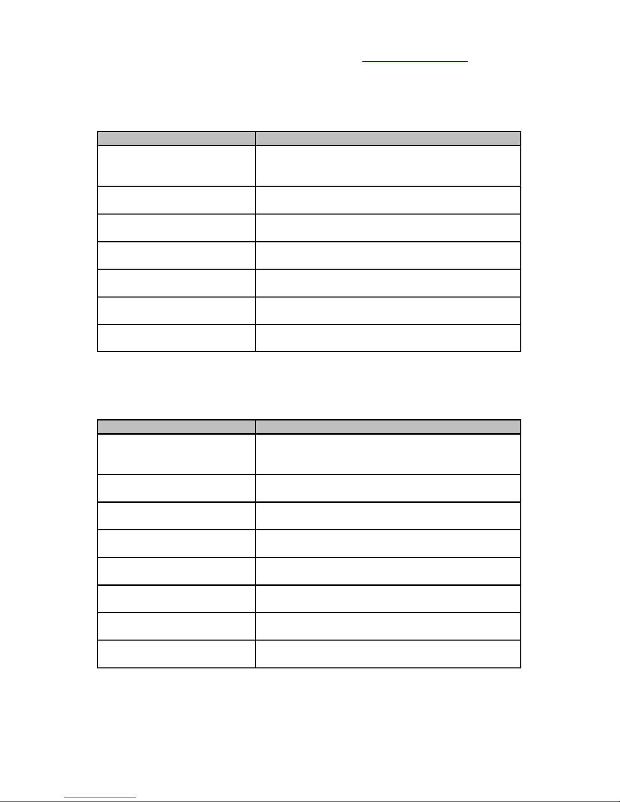
6.4 Verify Drives Procedure
The following table describes the sequence associated with performing a verify
operation of each target drive using the button panel interface.
LCD interface Comments
SuperDuper 2-01
Status: Ready
Drives: 12345678
From the main window, press <menu> to
display the initial menu item.
1:System Test
Press < menu > again to advance to the next
menu item.
2:Clone Drive
Press < menu > again to advance to the next
menu item.
3:Verify Drives
Press <enter> to execute the verify drives
command.
Verify SHA Data
OK (enter/cancel)?
Press <enter> to acknowledge that you want to
proceed.
Verifying 3.8GB/min
00:16:03 61GB/80GB
Interim status of the verify operation.
Operation Complete
The status displayed after it completes the
command.
6.5 Wipe Drives Procedure
The following table describes the sequence associated with performing a wipe
operation on each of the target drives using the button panel interface.
LCD interface Comments
SuperDuper 2-01
Status: Ready
Drives: 12345678
From the main window, press <menu> to
display the initial menu item.
1:System Test
Press < menu > again to advance to the next
menu item.
2:Clone Drive
Press < menu > again to advance to the next
menu item.
3:Verify Drives
Press < menu > again to advance to the next
menu item.
4:Wipe Drives
Press <enter> to execute the wipe drives
command.
Wipe Target Drives
OK (enter/cancel)?
Press <enter> to acknowledge that you want to
proceed.
Wiping 3.9GB/min
00:11:01 43GB/80GB
Interim status of the wiping operation.
Operation Complete
The status displayed after it completes the
command.
14
Page 19
Voom Technologies, Inc. © 2007-2013 Proprietary www.voomtech.com
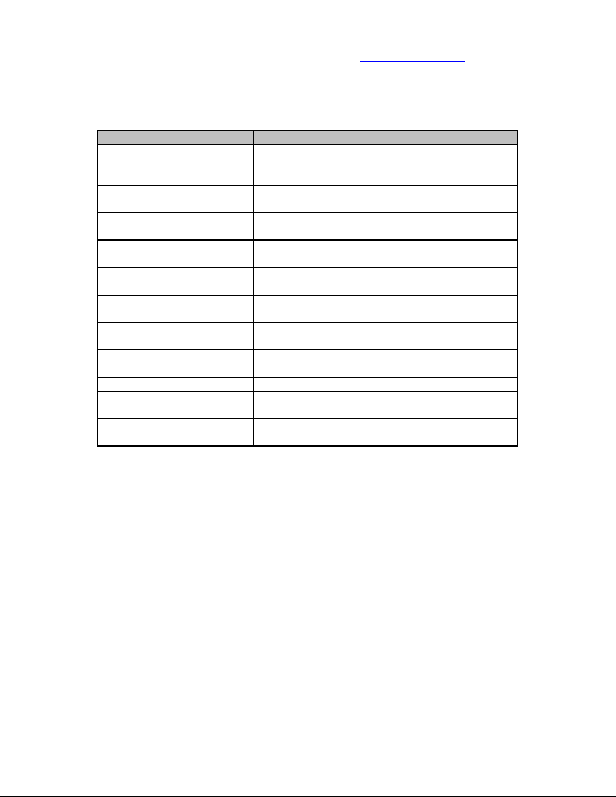
6.6 Remove HPA Procedure
The following table describes the sequence associated with removing a HPA
from each of the target drives using the button panel interface.
LCD interface Comments
SuperDuper 2-01
Status: Ready
Drives: 12345678
From the main window, press <menu> to
display the initial menu item.
1:System Test
Press < menu > again to advance to the next
menu item.
2:Clone Drive
Press < menu > again to advance to the next
menu item.
3:Verify Drives
Press < menu > again to advance to the next
menu item.
4:Wipe Drives
Press < menu > again to advance to the next
menu item.
5:Remove HPA
Press <enter> to execute the remove HPA
command.
Remove Target HPA
OK (enter/cancel)?
Press <enter> to acknowledge that you want to
proceed.
Removing Target 1
HPA
Interim status of the remove HPA operation.
. . .
Removing Target 8
HPA
Interim status of the remove HPA operation.
Operation Complete
The status displayed after it completes the
command.
15
Page 20
Voom Technologies, Inc. © 2007-2013 Proprietary www.voomtech.com
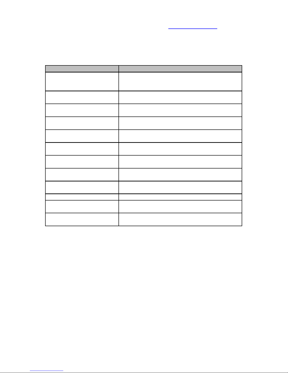
6.7 Remove DCO Procedure
The following table describes the sequence associated with removing a DCO
from each of the target drives using the button panel interface.
LCD interface Comments
SuperDuper 2-01
Status: Ready
Drives: 12345678
From the main window, press <menu> to
display the initial menu item.
1:System Test
Press < menu > again to advance to the next
menu item.
2:Clone Drive
Press < menu > again to advance to the next
menu item.
3:Verify Drives
Press < menu > again to advance to the next
menu item.
4:Wipe Drives
Press < menu > again to advance to the next
menu item.
5:Remove HPA
Press < menu > again to advance to the next
menu item.
6:Remove DCO
Press <enter> to execute the remove DCO
command.
Remove Target DCO
OK (enter/cancel)?
Press <enter> to acknowledge that you want to
proceed.
Removing Target 1
DCO
Interim status of the remove DCO operation.
. . .
Removing Target 8
DCO
Interim status of the remove DCO operation.
Operation Complete
The status displayed after it completes the
command.
16
Page 21
Voom Technologies, Inc. © 2007-2013 Proprietary www.voomtech.com
7 Serial Interface
With the SuperDuper unit turned off, connect the supplied serial cable between
the SuperDuper and a computer. Using a terminal program capable of serial
communications, such as HyperTerminal or Tera Term , configure the serial port
(usually COM1) as described in the table below:
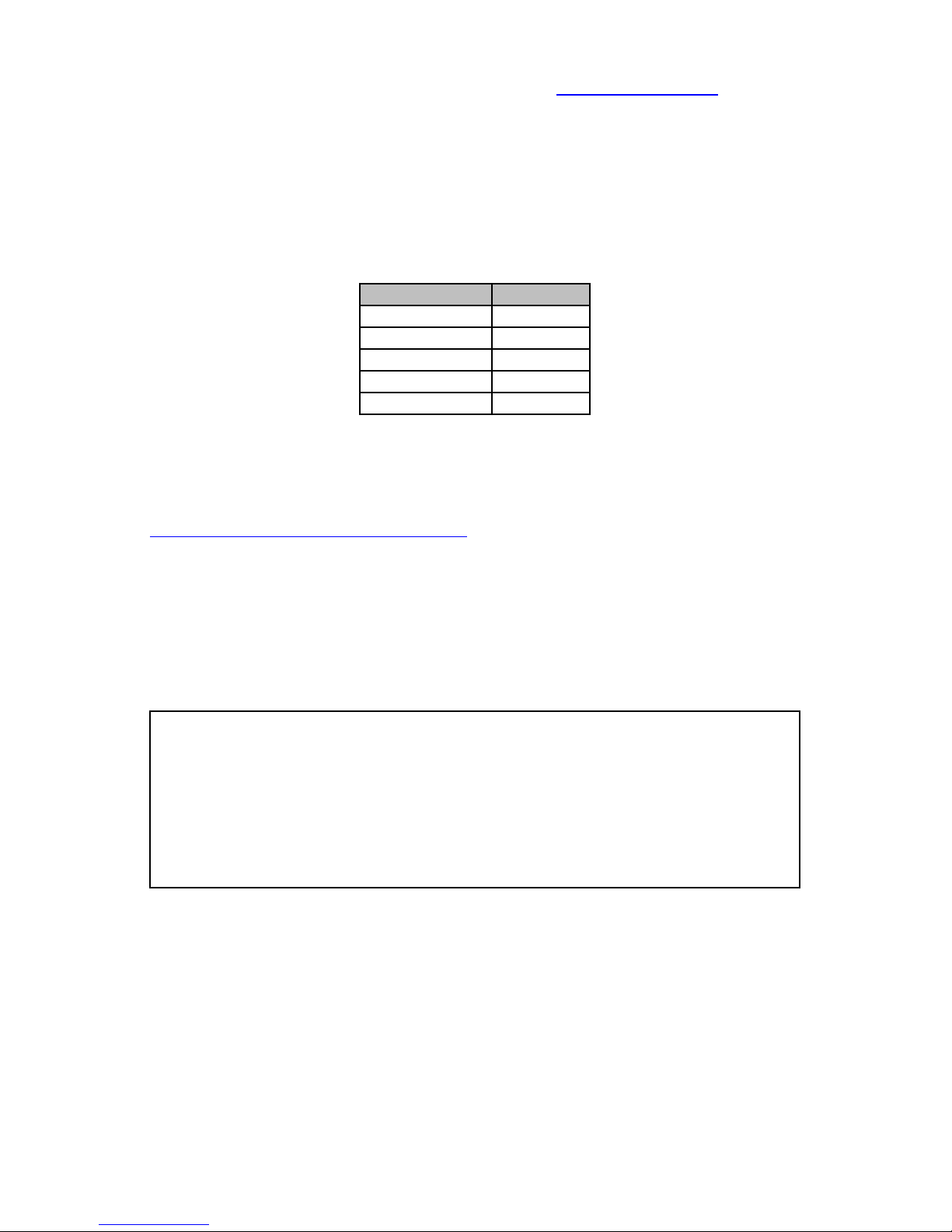
Parameter Value
Baud Rate 115200
Data Bits 8
Parity none
Stop Bits 1
Flow Control none
Serial Port Settings
Once the serial cable is connected and the terminal program configured, the
Shadow 3 unit may be turned on. For more detail on setting up a terminal
program please see the Other Documents on our website downloads page,
www.voomtech.com/content/downloads.
The serial interface provides the user access to additional commands, command
parameters, detailed status information, and detailed failure messages.
The serial interface command menu can be displayed anytime by entering help
or '?.' Any command options are preceded by a '-' and all optional parameters
are enclosed in brackets. The help command is shown below:
=> help
User Commands:
Test System configuration test
Clone [-vn] [blks] Clone Source drive to Target drives
Verify [blks] Verify all drives using SHA-256 hash
Wipe [blks] Wipe each of the Target drives
HPA Remove HPA from Target drives
DCO Remove DCO from Target drives
All examples provided in this chapter are of typical operation.
17
Page 22

Voom Technologies, Inc. © 2007-2013 Proprietary www.voomtech.com
7.1 System Test Procedure
When using the serial interface, the command syntax for testing the system
configuration is given below:
Test
=> Test
Test System Drives
OK (y/n)? y
Reading 32 sectors from Source drive
Reading 32 sectors from Target drive 1
Reading 32 sectors from Target drive 2
Reading 32 sectors from Target drive 3
Reading 32 sectors from Target drive 4
Reading 32 sectors from Target drive 5
Reading 32 sectors from Target drive 6
Reading 32 sectors from Target drive 7
Reading 32 sectors from Target drive 8
Operation Complete
7.2 Clone Drive Procedure
When using the serial interface, the command syntax for testing the system
configuration is given below:
Clone [-vn] [blks]
-n (n)o-wipe, disable the auto-wipe
-v (v)erify, re-verify destination
blks only clone blks sectors to destination
=> Clone
Clone Source Drive
OK (y/n)? y
Copying 78165360 sectors from Source drive to Target drives
00:00:10, 999936 sectors, 58.2MB/sec (3.0GB/min average)
00:00:20, 2161152 sectors, 58.2MB/sec (3.2GB/min average)
00:00:30, 3322368 sectors, 58.2MB/sec (3.3GB/min average)
. . .
00:14:33, 78165360 sectors, 43.6MB/sec (2.7GB/min average)
Clone Complete (00:14:33, 40.0GB)
Wiping 78136128 sectors from Target drive
00:00:10, 1128960 sectors, 56.8MB/sec (3.3GB/min average)
00:00:20, 2290176 sectors, 56.8MB/sec (3.3GB/min average)
00:00:31, 3451392 sectors, 56.8MB/sec (3.3GB/min average)
18
Page 23

Voom Technologies, Inc. © 2007-2013 Proprietary www.voomtech.com
. . .
00:14:08, 77607936 sectors, 32.7MB/sec (2.8GB/min average)
Target drive 1 is DONE [0x0000], [0x0001]
00:14:15, 78136128 sectors, 38.8MB/sec (2.8GB/min average)
Wipe Complete (00:14:15, 40.0GB)
Operation Complete (00:28:49, 80.0GB)
7.3 Verify Drives Procedure
When using the serial interface, the command syntax for verifying each of the
target drives is given below:
Verify [blks]
blks only verify blks sectors
=> Verify
Verifying SHA Data
OK (y/n)? y
Verifying 156301488 sectors on All drives
00:00:09, 838656 sectors, 32.1MB/sec (2.6GB/min average)
00:00:20, 1935360 sectors, 57.7MB/sec (2.9GB/min average)
00:00:30, 3096576 sectors, 57.8MB/sec (3.1GB/min average)
. . .
00:30:32, 156301488 sectors, 57.7MB/sec (2.9GB/min average)
Source SHA:
SHA_A:49bc20df15e412a64472421e13fe86ff
SHA_B:1c5165e18b2afccf160d4dc19fe68a14
Drive 1 SHA:
SHA_A:49bc20df15e412a64472421e13fe86ff
SHA_B:1c5165e18b2afccf160d4dc19fe68a14
. . .
Drive 8 SHA:
SHA_A:49bc20df15e412a64472421e13fe86ff
SHA_B:1c5165e18b2afccf160d4dc19fe68a14
Verify Passed
19
Page 24

Voom Technologies, Inc. © 2007-2013 Proprietary www.voomtech.com
7.4 Wipe Drives Procedure
When using the serial interface, the command syntax for wiping each of the
target drives is given below:
Wipe [blks]
blks only wipe blks sectors
=> Wipe
Wipe Target Drives
OK (y/n)? y
Wiping 156301488 sectors on Target drives
00:00:10, 1161216 sectors, 67.7MB/sec (3.4GB/min average)
00:00:20, 2515968 sectors, 67.8MB/sec (3.7GB/min average)
00:00:30, 3870720 sectors, 67.8MB/sec (3.8GB/min average)
. . .
00:24:41, 155860992 sectors, 32.8MB/sec (3.2GB/min average)
Adjusted sector transfer count on drive 3 to 0x000052b0
Wipe operation on drive 3 is complete!
Target drive 3 is DONE [0x0000], [0x0004]
00:24:47, 156301488 sectors, 44.9MB/sec (3.2GB/min
average)
Operation Complete (00:24:47, 80.0GB)
7.5 Remove HPA Procedure
When using the serial interface, the command syntax for removing a HPA from
each of the target drives is given below:
HPA
=> HPA
Remove Target HPA
OK (y/n)? y
Removing HPA from Target drive 1
Removing HPA from Target drive 2
Removing HPA from Target drive 3
Removing HPA from Target drive 4
Removing HPA from Target drive 5
Removing HPA from Target drive 6
Removing HPA from Target drive 7
Removing HPA from Target drive 8
Operation Complete
20
Page 25

Voom Technologies, Inc. © 2007-2013 Proprietary www.voomtech.com
7.6 Remove DCO Procedure
When using the serial interface, the command syntax for removing a DCO from
each of the target drives is given below:
DCO
=> DCO
Remove Target DCO
OK (y/n)? y
Removing DCO from Target drive 1
Removing DCO from Target drive 2
Removing DCO from Target drive 3
Removing DCO from Target drive 4
Removing DCO from Target drive 5
Removing DCO from Target drive 6
Removing DCO from Target drive 7
Removing DCO from Target drive 8
Operation Complete
21
Page 26

Voom Technologies, Inc. © 2007-2013 Proprietary www.voomtech.com
8 Special Precautions
This chapter describes some scenarios that require special attention in order to
prevent unexpected results when operating the duplicating unit. Each of these
situations is described in detail below:
8.1 Using the Buttons
The system automatically de-bounces each of the switch operations. In addition,
to avoid unexpected results caused by “double-clicking” any of the buttons, all
previous button status is cleared after each prompting message is displayed to
the LCD. Therefore, each prompting message will be displayed for a minimum of
0.5 seconds before the unit will respond to any operator input from the buttons.
In addition, the buttons will be disabled whenever the duplicating unit is
processing an error condition. Whenever this occurs, a message will be
displayed to the LCD indicating that it is both processing an error condition and
that the buttons are disabled. Once the error condition has been processed, the
buttons will automatically be enabled once again.
8.2 Target Drive Size Limitations
While the system can accommodate writing to an assortment of different size
target drives, you must be aware of the following limitation:
● When executing a Clone command, if one target drive is larger than
another target drive, a portion of the larger target drive will not be
accessible.
22
Page 27
Voom Technologies, Inc. © 2007-2013 Proprietary www.voomtech.com
9 Troubleshooting
This chapter describes possible operation failures that may occur during the
execution of the commands previously described. Since the same information is
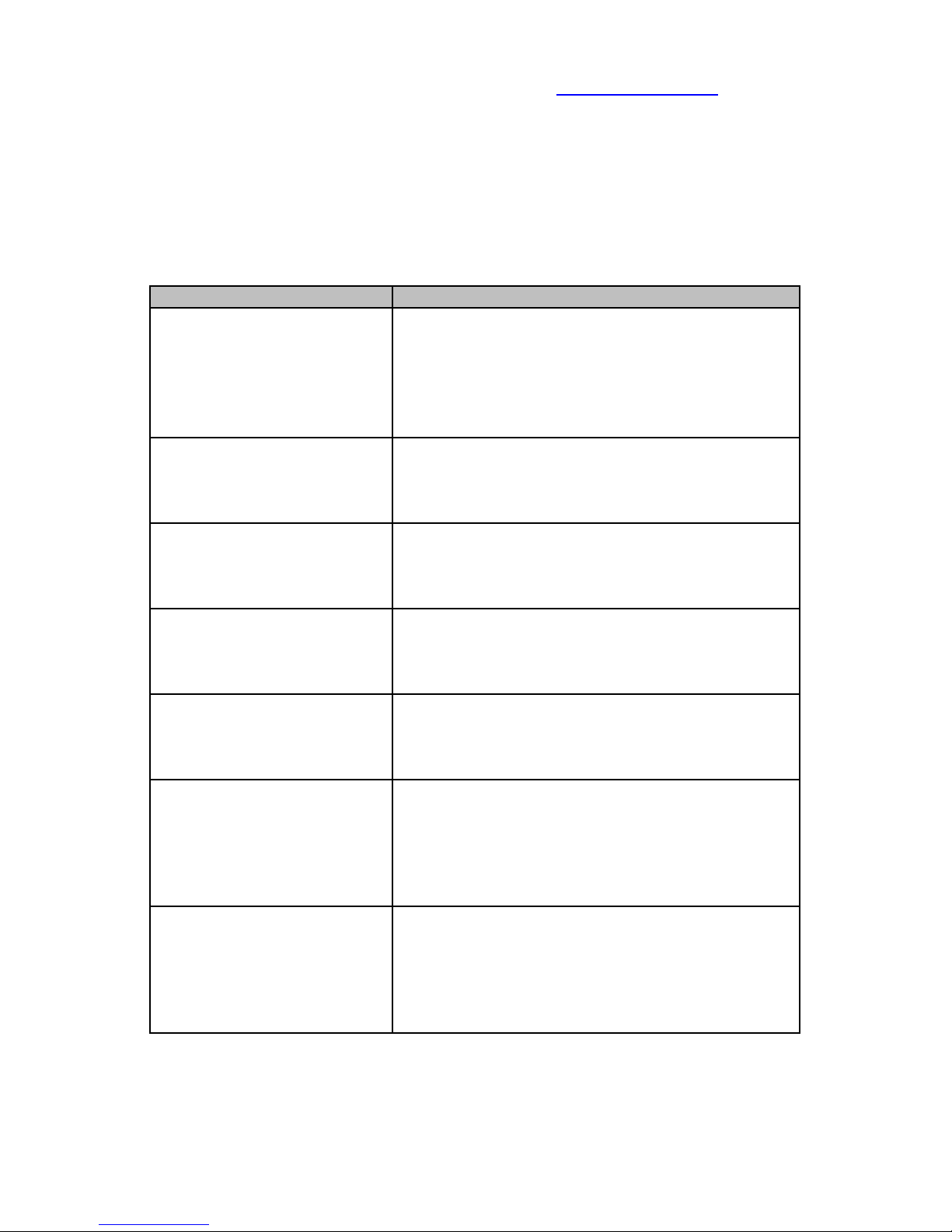
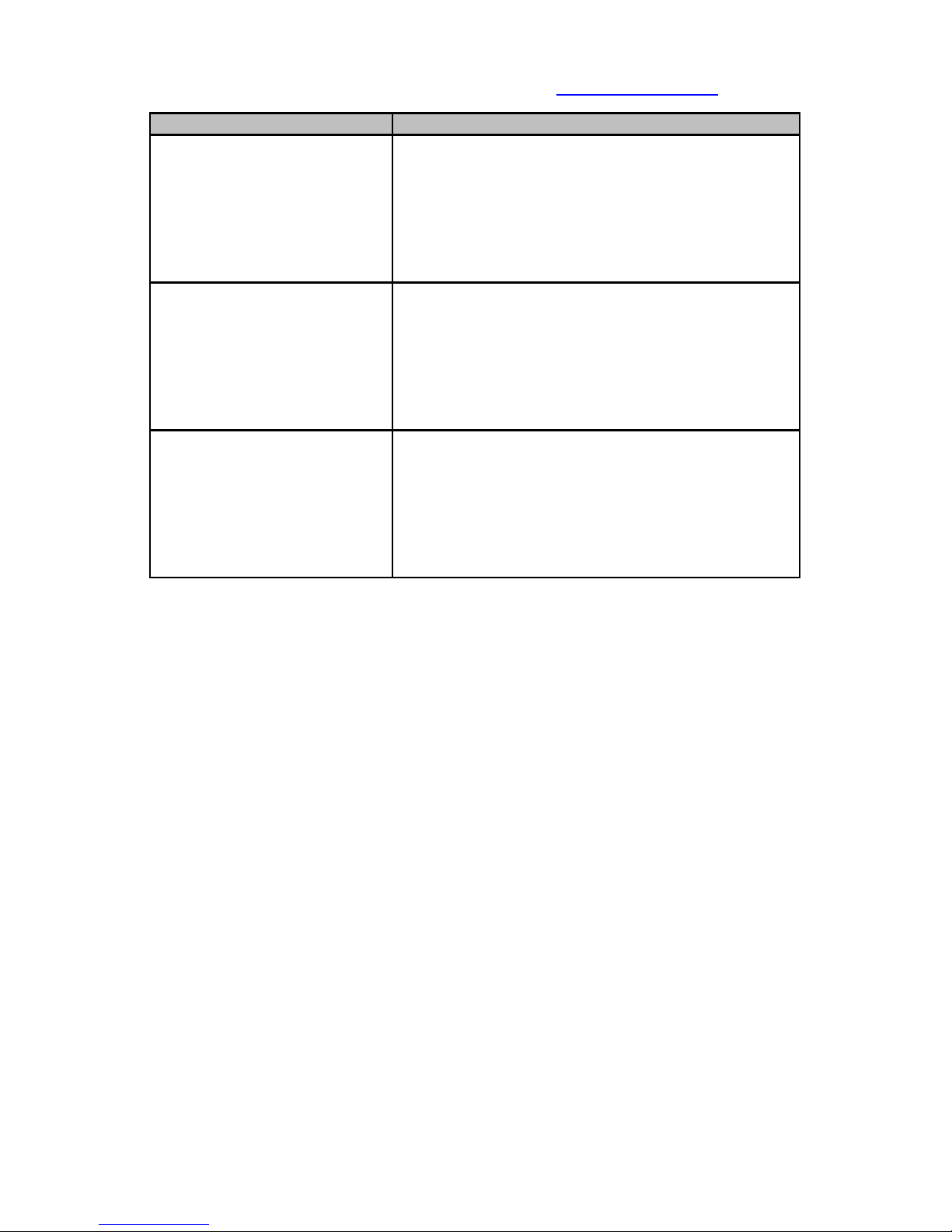
displayed to both the LCD and the serial interface the LCD format is shown in
the following table.
LCD information Error Explanation
Source/Target Drive
- no drive found
No power to the drive.
No ATA cable to a drive.
Unable to identify a drive.
Hint: Make sure that each of the drives is
securely connected to the SuperDuper unit.
Source/Target Drive
-read error
A read error was detected while reading
data from a drive.
Hint: Replace the drive.
Source/Target Drive
-write error
A write error was detected while copying
data to a drive.
Hint: Replace the drive.
Source/Target Drive
-not enough capacity
The source drive is larger than the smallest
target drive.
Hint: Install a larger target drive.
Operation Failed
-Source read error
Unable to recover from a read error on the
Source drive.
Hint: First check cables, then replace drive.
Operation Failed
-Target read error
Unable to recover from a read error on one
of the Target drives, but could not
determine which Target drive was at fault.
Hint: Manually remove one drive at a time until
the problem is resolved.
Operation Failed
-Target write error
Unable to recover from a write error on one
of the Target drives, but could not
determine which Target drive was at fault.
Hint: Manually remove one drive at a time until
the problem is resolved.
23
Page 28
Voom Technologies, Inc. © 2007-2013 Proprietary www.voomtech.com
LCD information Error Explanation
Operation Failed
-Drive read error
Unable to recover from a read error, but
could not determine if it was the Source
drive or one of the Target drives.
Hint: Manually remove one Target drive at a
time until the problem is resolved. If the
problem persists, replace the Source drive.
Operation Failed
-Drive write error
Unable to recover from a write error, but
could not determine if it was the Source
drive or one of the Target drives.
Hint: Manually remove one Target drive at a
time until the problem is resolved. If the
problem persists, replace the Source drive.
Operation Failed
-Drive access error
Unable to recover from an error, but could
not determine either the type of access or
which drive that was at fault.
Hint: Manually remove one Target drive at a
time until the problem is resolved. If the
problem persists, replace the Source drive.
24
Page 29

Voom Technologies, Inc. © 2007-2013 Proprietary www.voomtech.com
10 Warranty
10.1 Limited Warranty
Voom Technologies, Inc. (VoomTech) warrants the SuperDuper hardware
against defects in material and workmanship under normal use and service for
one (1) year from the original date of purchase. Voom, at its option, shall repair
or replace the defective unit covered by this warranty.
VoomTech does not warrant this product to be free of interruption or errors.
This warranty covers only defects that arise from normal usage of the product, as
it is intended by Voom and indicated in this User Guide and does not cover other
issues, including those arising from:
● Improper maintenance or handling,
● Use of parts or supplies not included with the product or approved for
usage by VoomTech,
● Operations that deviate from those intended or indicated in this User
Guide,
● Misuse or abuse of the product, modification of the product that is
unauthorized by Voom, subjecting the product to abnormal working
conditions (including, but not limited to, water or lightning damage) or
tampering with the product.
Upon notification of defect in materials or workmanship and return of the product
in accordance with the Warranty Return Instructions (below) and in concurrence
with the warranty conditions as indicated above, VoomTech shall either repair or
replace the product at its discretion. VoomTech reserves the right to replace the
product with a new or like-new product that has functionality equal to or
exceeding that of the originally purchased product.
Voom will be obligated to repair or replace the product only after the product has
been returned according to the instructions below and has been received by
VoomTech.
This warranty is valid only if the product is used in conjunction with devices
indicated in this User Guide.
Repair or replacement as provided under this warranty is the exclusive remedy of
the purchaser. This warranty is in lieu of all other warranties, express or implied,
including any implied warranty of merchantability or fitness for a particular use or
purpose, and Voom Technologies, Inc., shall in no event be liable to purchaser
for indirect or consequential damages of any kind or character.
Some states do not allow the exclusion or limitation of incidental or consequential
damages or allow limitations on how long an implied warranty lasts, so the above
25
Page 30

Voom Technologies, Inc. © 2007-2013 Proprietary www.voomtech.com
limitations or exclusion may not apply to you. This warranty gives you specific
legal rights, and you may also have other rights that vary from state to state.
10.1.1 Wearable Parts
The DC power and data cables are subject to wear and should be replaced on a
regular basis. To save wear on the connectors located on the SuperDuper main
unit it is recommended that the cables be left plugged into the SuperDuper until
the cables require replacement. The DC power cables and data cables are
considered “wearable” parts and as such are not covered under the warranty
except for initial manufacturer defects.
10.2 Warranty Return Instructions
For timely warranty repair and return of the Product please follow the procedure
outlined below.
1. Contact a VoomTech representative (651-998-1618) to obtain a Return
Material Authorization (RMA) number.
2. Please be prepared to provide the VoomTech representative with the
product serial number, the invoice number and the date of purchase in
order to facilitate this process.
3. Once you receive a RMA number, please pack the Product in its original
packaging or any other secure box so that no damage may occur.
4. Deliver the Product shipping prepaid to:
Voom Technologies, Inc.
110 Saint Croix Trail South
Lakeland MN 55043
Attention: RMA _______
5. Shipping with proper insurance and a tracking number is highly advised.
6. Please be sure to include in the return package complete contact
information including return shipping information. Please also include a
brief description of the problem and a copy of the RMA number.
7. If you do not obtain an RMA, your return will not be able to be
processed immediately and may be returned unprocessed.
NOTE: Voom Technologies, Inc. is not responsible for items lost or
damaged in transit.
26
Page 31
Voom Technologies, Inc. © 2007-2013 Proprietary www.voomtech.com
11 Specifications
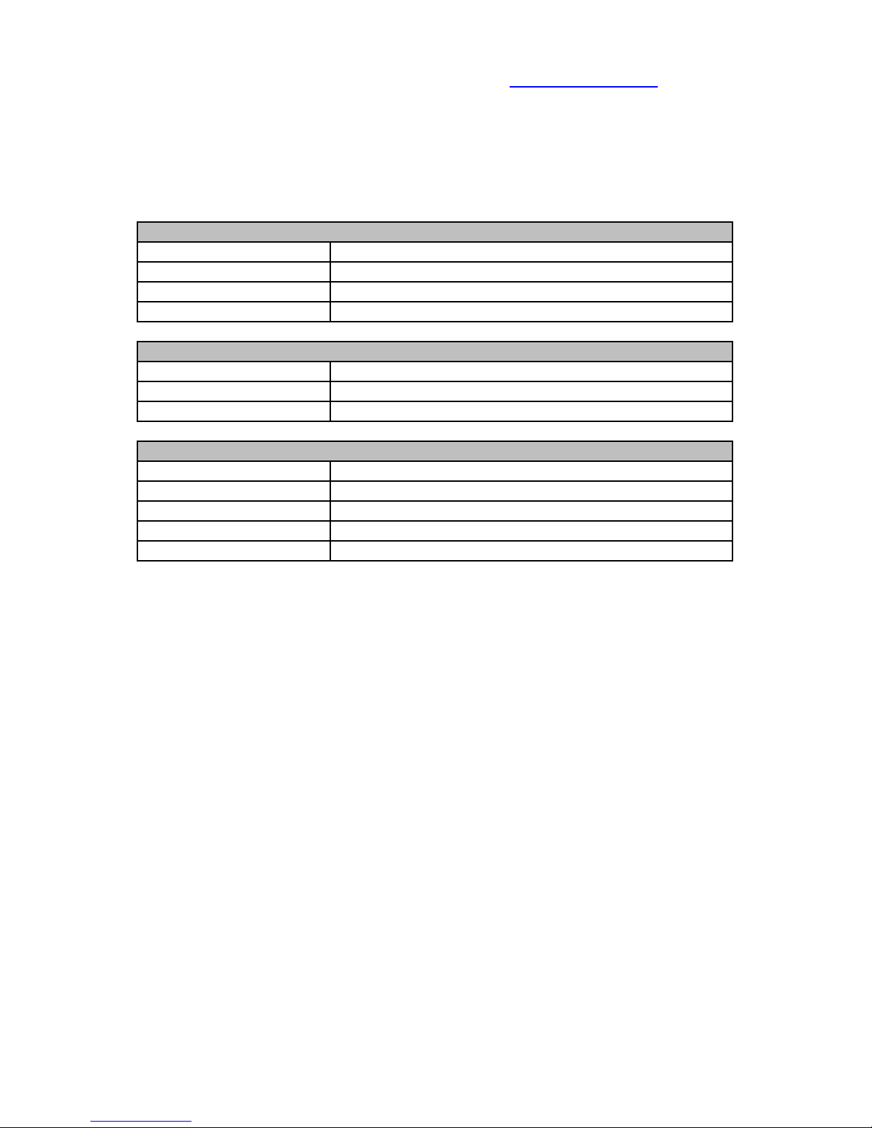
This chapter describes the specifications for the Model No. VMSD-P1 Hard Drive
Duplicating Unit. Specifications subject to change without notice.
AC Electrical Requirements
Voltage 100-240V auto ranging
Frequency 50-60 Hz
Input Current 12A @ 115V / 6A @ 230V
Output Watts 500 W
Operating Environment
Temperature 50 to 95 Degrees F
Relative Humidity 20% to 80% (non condensing)
Altitude 0 to 8000 Feet
Physical Characteristics
Height (chassis) 6 inches (152.4 mm)
Height (light tower) 17.375 inches (441.325 mm)
Width 17 inches (431.8 mm)
Depth 21 inches (533.4 mm)
Weight 22 pounds (10 kg)
11.1 CE
Users need to notify any information technology equipment users within a 60
meter radius that SuperDuper may interfere with other electronic equipment.
Although the manufacturer has not observed electromagnetic interference from
the SuperDuper with other electronic equipment in its development lab or offices,
this is not an indication that the user will not experience electromagnetic
interference from the SuperDuper with other electronic equipment within the 60
meter radius.
11.2 FCC Exemption
This device is exempt from FCC regulations under Part 15, Section 103 c.
27
 Loading...