

VooDoo DCR 6024, DCR 6128, DCR 6000 Planning & Installation Manual
DCR 6024 / 6128 / 6000
MEDIA RECORDER
Bild im Format 16:9
Planning & Installation Manual

BTS Media Solutions GmbH
Brunnenweg 9
D-64331 Weiterstadt, Germany
P.O. Box 1 165
Tel: +49 (0) 6155-870-0
Fax: +49 (0) 6155-870-300
Für diese Unterlage behalten wir uns alle
Rechte vor (Gemäß DIN 34).
Technische Änderungen im Zuge der
Weiterentwicklung vorbehalten.
Copying of this document and giving it to
others, and the use or communication of
the contents thereof, are forbidden without
expressed authority. Of fenders are liable to
the payment of damages. All rights are reserved in the event of the grant of a patent
or the registration of a utility model or design.
Liable to technical alterations in the course
of further development.
Toute communication ou reproduction de
ce document, toute exploitation ou communication de son contenu sont interdites,
sauf autorisation expressé. T out manquement à cette règle est illicite et expose son
auteur au versement de dommages et
intérêts. Tous nos droits sont réservés
pour le cas de la délivrance d’un brevet ou
de l’enregistrement d’un modèle d’utilité.
Sous réserve de modification au cours de
l’évolution technique.
BTS Media Solutions GmbH 2001
Copyrights
Published by

ContentsDCR 6024/6128/6000
I
Planning & Installation – Rev. 1 / 7. 2001
CONTENTS
Page
Safaty Instructions
1. General 1 – 1
1.1 Features 1 – 1
1.2 Overview 1 – 3
1.3 Mechanical design 1 – 6
1.4 Machine control 1 – 7
1.5 Blockdiagram 1 – 9
1.6 Functional overview 1 – 13
1.6.1 D–6 Standard 1 – 13
1.6.2 DTV Processor DTV 6024 1 – 17
1.6.3 Data Processor DDP 6128 1 – 20
1.6.4 Tape Deck DMS 6000 1 – 22
1.6.5 Scanner Assemply 1 – 28
1.6.6 Control Panel DCH 6024 CP 1 – 30
1.6.7 Data Switch DSW 6000 1 – 31
2. Technical Specifications 2 – 1
2.1 General 2 – 1
2.2 Tape Deck / Recording System 2 – 2
2.3 DTV System 2 – 4
2.3.1 Video 2 – 4
2.3.2 Audio 2 – 6
2.3.3 Cue Audio 2 – 7
2.3.4 Control 2 – 7
2.4 Data System 2 – 8
2.4.1 Data Input / Output 2 – 8
2.4.2 DPX Monitoring 2 – 8
2.4.3 Control 2 – 8
2.5 Inputs / Outputs 2 – 9
2.5.1 Tape Deck DMS 6000 2 – 9
2.5.2 DTV Processor DTV 6024 2 – 10
2.5.3 Data Processor DDP 6128 2 – 1 1
2.5.4 Data Switch DSW 6000 2 – 1 1

Contents
DCR 6024/6128/6000
II
Planning & Installation – Rev. 1 / 7. 2001
3. Installation 3 – 1
3.1 Unpacking and repacking 3 – 1
3.2 Mechanical dimensions 3 – 2
3.3 Ventilation 3 – 5
3.4 Mounting 3 – 8
3.4.1 Mounting Tapedeck on Processor 3 – 8
3.4.2 Mounting Tapedeck and Processor side by side 3 – 10
3.4.3 Mounting Versions of DCR 6000 3 – 11
3.4.4 Mounting into a 19-inch cabinet 3 – 13
3.4.4.1 Safety Hazards 3 – 13
3.4.4.2 DCR 6024 built in into a19 inch cabinet 3 – 14
3.4.5 Installing Control Panel as Remote Panel 3 – 15
3.4.6 Installing Control Panel as Local Panel 3 – 16
3.5 Standard connections DCR 6024 3 – 17
3.5.1 Connect the connection cables 3 – 18
3.6 Standard connections DCR 6128 3 – 20
3.6.1 Connect the connection cables 3 – 21
3.7 Standard connections DCR 6000 3 – 23
3.7.1 Connect the connection cables 3 – 24
4. Connections 4 – 1
4.1 Rear View DMS 6000 4 – 1
4.2 Rear View DTV 6024 4 – 2
4.3 Rear View DDP 6128 4 – 3
4.4 Rear View DMS 6000 4 – 4
4.5 Terminal Panel – T apedeck DMS 6000 4 – 5
4.5.1 AC power terminal unit BD 5146 4 – 7
4.5.1.1 Grounding 4 – 7
4.5.1.2 Mains connection 4 – 10
4.5.2 Processor Interface 4 – 11
4.5.3 Timecode IN/OUT (DTV Mode) 4 – 12
4.5.4 iMCS 4 – 13
4.5.5 Remote Control REM 1, REM 2, REM 3, RS 232C 4 – 14
4.5.6 Waveform Monitoring 4 – 15
4.5.7 Connection Control Panel and headphone with
volume adjustment 4 – 16
4.6 Terminal Panel – Processor DTV 6024 4 – 17
4.6.1 AC power terminal 4 – 19
4.6.1.1 Grounding 4 – 19
4.6.1.2 Mains connection 4 – 20
4.6.2 Tapedeck Interface 4 – 21
4.6.3 Video Analog Monitor Out 4 – 22
4.6.4 Audio Digital In/Out 4 – 23
4.6.5 Audio Monitoring 4 – 24
4.6.6 Audio Sync (48 kHz) 4 – 25
4.6.7 SDTV / NTSC Sync Out 4 – 25
4.6.8 Playback Ref Sync 4 – 25
4.6.9 iMCS 4 – 26

ContentsDCR 6024/6128/6000
III
Planning & Installation – Rev . 1 / 7. 2001
4.7 Terminal Panel – Processor DDP 6128 4 – 27
4.7.1 AC power terminal 4 – 29
4.7.1.1 Grounding 4 – 29
4.7.1.2 Mains connection 4 – 30
4.7.2 Tapedeck Interface 4 – 31
4.7.3 DPX Monitor Out (Option) 4 – 32
4.7.4 HIPPI In/Out 4 – 33
4.7.5 Network Interface 4 – 33
4.7.6 IMCS 4 – 34
5. Startup 5 – 1
5.1 Installation check 5 – 1
5.2 Switching on 5 – 2
5.2.1 Selecting the HD Standard / Data Mode 5 – 4
5.3 Selecting Machine Address 5 – 5
5.4 Control of the Input / Reference signal 5 – 6
5.4.1 DTV Mode 5 – 6
5.4.2 Data Mode 5 – 7
5.5 Operation 5 – 8
6. Interfaces 6 – 1
6.1 RS422 ES - Bus
REM 1 ES-Bus Port according to EBU-Tech 3245-E 6 – 1
6.2 REM 2 IN - RS422A Interface BBE 6 – 6
6.3 REM 2 OUT – RS422A Interface BBE 6 – 15
7. DTV Applications 7 – 1
7.1 List of external devices able to control DCR 6024 7 – 1
7.1.1 VTR editors 7 – 1
7.1.2 Telecine controllers 7 – 1
7.2 Operation under control of Editing- and Graphic Systems 7 – 2
7.3 Parameter Sheets BBE 900 7 – 3
7.4 Parameter Sheets BVE 9000 7 – 4
7.5 More Parameter Sheets (in preparation) 7 – 5
8. Data Applications 8 – 1
8.1. Specter / Transfer Engine / Mover (in preparation) 3-3
9. Index 9 – 1

LISTED
PROFESSIONAL VIDEO EQUIPMENT
3S13 / 78MA
U
L
®
LISTED
UL 1950
3S13 / 78MA
U
L
®
Safety InstructionsDCR 6024/6128/6000DCR 6024/6128/6000
I
Planning & Installation – Rev . 1 / 7. 2001
SAFETY INSTRUCTIONS
The DCR 6024/6128/6000 is a digital HDCassette Recorder System designed for
recording and playback of video / audio and / or data signals for various DTV– and
data standards, according to the SMPTE / D-6 HD-recording format.
The DCR 6024/6128/6000 consists of basic modules:
Tapedeck DMS 6000
incl. Control Panel DCH 6024 CP
DTV Processor DTV 6024
Data Processor DDP 6128
Data Switch DSW 6000
To ensure safe operation please observe the following directions:
The current and voltages present in this equipment are dangerous. All personnel must at all times follow the safety regulations.
Always disconnect power before removing covers or panels. Always discharge high voltage points before servicing.
Never make internal adjustments, perform maintenance or service when
alone or fatigued.
In case of an emergency ensure that the power is disconnected.
Any interruption of the protection conductor inside or outside the apparatus,
or disconnection of the protective earth terminal, is likely to make this apparatus dangerous. Intentional interruption is prohibited.
The DCR 6024/6128/6000 VooDoo Media Recorder is designed accordingly to
regulations of the Underwriters Laboratories Inc. Northbrook, Illinois US, certificated and registered under file no.:
E184475 (Tapedeck) /
E205276 (DTV Processor)
E159262 (Data Processor)
E159262 (Data Switch)
Conform with the following European directives and CE marked:
Safety: Low voltage directive 73/23/EEC, EN 60 950/1997
EMC / EMI: EMC directive 89/336/EEC,
EN 55103-1/1996,
EN 55103-2/1996
EN 55022/1998
Electromagnetic environment (acc. to EN 55103–1) E4
Warning:
This is a class A product. In a domestic environment this product may
cause radio interference in which
case the user may be required to take
adequate measures.
Warnung:
Dies ist eine Einrichtung der Klasse
A. Diese Einrichtung kann im
Wohnbereich Funkstörungen
verursachen; in diesem Fall kann vom
Betreiber verlangt werden,
angemessenen Massnahmen
durchzuführen.
Application
Warnings!
Safety Instructions DCR 6024/6128/6000
II
Planning & Installation – Rev . 1 / 7. 2001
EMC: AS/NZS 3548
This unit was designed for use under controlled EMC environment (for example
purpose built broadcasting or recording studio), and the rural outdoors environment (far away from railways, transmitters, overhead power lines, etc.).
FCC 47 Part 15 Class A
This equipment has been tested and found to comply with the limits for a Class A
digital device, pursuant to the part 15 of the FCC Rules and EN 55022. These limits
are designed to provide reasonable protection against harmful interference when
the equipment is operated in a commercial environment.
This equipment generates, uses, and can radiate radio frequency energy and, if
not installed and used in accordance with the instruction manual, may cause harmful interference to radio communications.
Operation of this equipment in a residential area is likely to cause harmful
interference in which case the user will be required to correct the interference at his own expense.
The EMC regulations are only applicable when correctly shielded cables are used
for installation of the equipment. This applies to video cables as well as control
cables. Corresponding cables can be obtained from Thomson.
Run all connection cables in covered cable ducts (risk of stumbling).
The DCR 6024/6128/6000 includes wide range power supply units of 100 – 240 V,
so that no changeover is required for different line voltages. Depending on the supply voltage use the proper rated power supply cord.
For more details see section 5 ”Installation” in the Planning & Installation manual.
Caution! Double-pole or neutral fusing
Risk of electric shock. Grounded circuit conductor (neutral) provided with over-current protection.
After operation of the protective device, parts of the equipment that remain under
voltage might represent a hazard during servicing.
Disconnect power before servicing!
The Tapedeck DMS 6000 is protected by two primary-side fuses (T6.25A / 250V)
which are located on the rear panel.
When replacing this fuse, make sure that a fuse link of the same type and of the
same current rating is used.
Never use a mended fuse! Do not short-circuit the fuseholder!
EMC Environment
FCC Rules
§ 15.105
EN 55022
Connection cables
Mains Voltage
Installation
Fuses of
Tapedeck
Safety InstructionsDCR 6024/6128/6000DCR 6024/6128/6000
III
Planning & Installation – Rev . 1 / 7. 2001
The signal Processors DTV 6024 and DDP 6128 and Data Switch DSW 6000 are
protected by an automatic fuse, which is located on the Processor rear panel.
The DCR 6024/6128/6000 may only be operated in closed condition.
Opening the covers or removing parts with tools may give access to live parts.
Therefore the system must be completely disconnected from the mains before any
cover is opened.
If, however, working on the opened machine is inevitable, this may only be done by
an expert who is familiar with the dangers involved.
Beware of high speed rotating video heads.
Wear safety glasses!
Warning !
ATTENTION! Capacitors may still be charged!
If, for example due to a failure, safe operation of the DCR 6024/6128/6000 is no
longer possible, take the unit out of operation and secure it against further use.
The Tapedeck contains two backup batteries type Varta CR 1/2 AA Thomson
part no. 003 1 19 100 195 which have to be replaced with batteries of the same
type (UL-1642 listed).
Battery replacement should be done by Thomson service personnel only .
Fuse of
Processor
During operation
Working on the
opened machine
Capacitors
Batteries

Safety Instructions DCR 6024/6128/6000
IV
Planning & Installation – Rev . 1 / 7. 2001

1. GeneralDCR 6024/6128/6000
1 – 1
Planning and Installation – Rev. 1 / 7. 2001
1. GENERAL
1.1 FEATURES
1.1.1 GENERAL
Digital film and the 1080p universal mastering format are increasingly important in
post production applications. Besides the digital HD video formats the data format
using SMPTE–rated DPX ( digital picture exchange) file format for uncompressed
storage and transport of picture information is required. This data format allows
higher resolution than specified in video formats with similar freedom in transfer
characteristic, color space and so on.
The DCR 6024/6128/6000 supports the HD video formats (1920x1080) as well as
data recording of DPX picture information. Using the same tapedeck and different
processors for DTV and data applications the system can be configured for the
requested application. With the addition of the data switch the same tapedeck can
be used to record data or digital HD video in many formats.
1.1.2 HDTV RECORDER DCR 6024
The DCR 6024 is a digital component HDTV Cassette Recorder designed for acquisition, production, postproduction and archiving of video and audio signals for
various HD-standards, according to the SMPTE/D-6 HD-recording format.
Operating in HD standards HD-SDI IN / OUT SMPTE 292M:
1920 x 1080 @ 24p
1920 x 1080 @ 23.97p Progressive modes
1920 x 1080 @ 25p
1920 x 1080 @ 24sF
1920 x 1080 @ 23.97sF ”segmented frame” modes
1920 x 1080 @ 25sF
1920 x 1080 @ 60i
1920 x 1080 @ 59.94i 2:1 interlace modes
1920 x 1080 @ 50i
10 (60i), 12 (24p, 25p, 24sF, 50) digital Audio in- and outputs according to
AES Standard
Crossplay between varoius modes
Timecode conversion in crossplay modes
Visible search 15 times regular speed
Broadcastable slowmotion range – 0.25 to + 0.25 regular speed
Automatic Tracking adjustment
Automatic playback equalization
Integrated two machine editor

1. General DCR 6024/6128/6000
1 – 2
Planning and Installation – Rev. 1 / 7. 2001
Control Panel with slot for personal card to store individual setups
Integrated ASTC (Audio Sector Time Code)
1 Video Component output analog R/G/B/S switchable to Y/P
R/PB
for Monito-
ring. In 24(23.97)p mode the output is switchable to 60i (2/3 pulldown)
Remote control interfaces: ESBUS , RS422 SONY protocol, iMCS
Option BD 5402:
2 Audio analog outputs for monitoring (L/R)
1 Headphone output
1.1.3 DA TA RECORDER DCR 6128
Data recorder system for recording and playback of image data and general
purpose data (instrumentation recording)
Data rates up to 128 MBtes/sec
128 MBytes/sec in instrumentation mode (without rewrites)
100MBytes/sec in Hippi mode (with rewrites)
500 GBytes max capacity on large cassette
Hippi serial optical interface for data transfer
iMCS remote control for links to telecines and other Thomson film imaging
products
Flexibilty to adopt future high speed data interfaces
Option BD 5456
DPX monitor for dispaying DPX data on a XGA monitor (1024x768)
1.1.4 DIGITAL FILM APPLICATION SYSTEM DCR 6000
Digital Film Applications (DFA) system which combines the DCR 6024 (H)DTV
recorder and the DCR 6128 Data Recorder to a versatile, switchable system.
A DSW 6000 Data Switch allows to use the DMS 6000 tapedeck for both DTV and
data applications. A changeover from data to DTV mode can be done within
seconds.
1. GeneralDCR 6024/6128/6000
1 – 3
Planning and Installation – Rev. 1 / 7. 2001
1.2 OVERVIEW
1.2.1 HDTV RECORDER DCR 6024
The DCR 6024 consists of two basic modules:
Tapedeck DMS 6000
incl. Control Panel DCH 6024 CP
DTV Processor DTV 6024
Tapedeck
Processor
Control
Panel
Fig. 101: HDTV Recorder DCR 6024

1. General DCR 6024/6128/6000
1 – 4
Planning and Installation – Rev. 1 / 7. 2001
1.2.2 DA TA RECORDER DCR 6128
The DCR 6128 consists of two basic modules:
Tapedeck DMS 6000
incl. Control Panel DCH 6024 CP
Data Processor DDP 6128
Tapedeck
Processor
Control
Panel
Fig. 102: Data Recorder DCR 6128
1. GeneralDCR 6024/6128/6000
1 – 5
Planning and Installation – Rev. 1 / 7. 2001
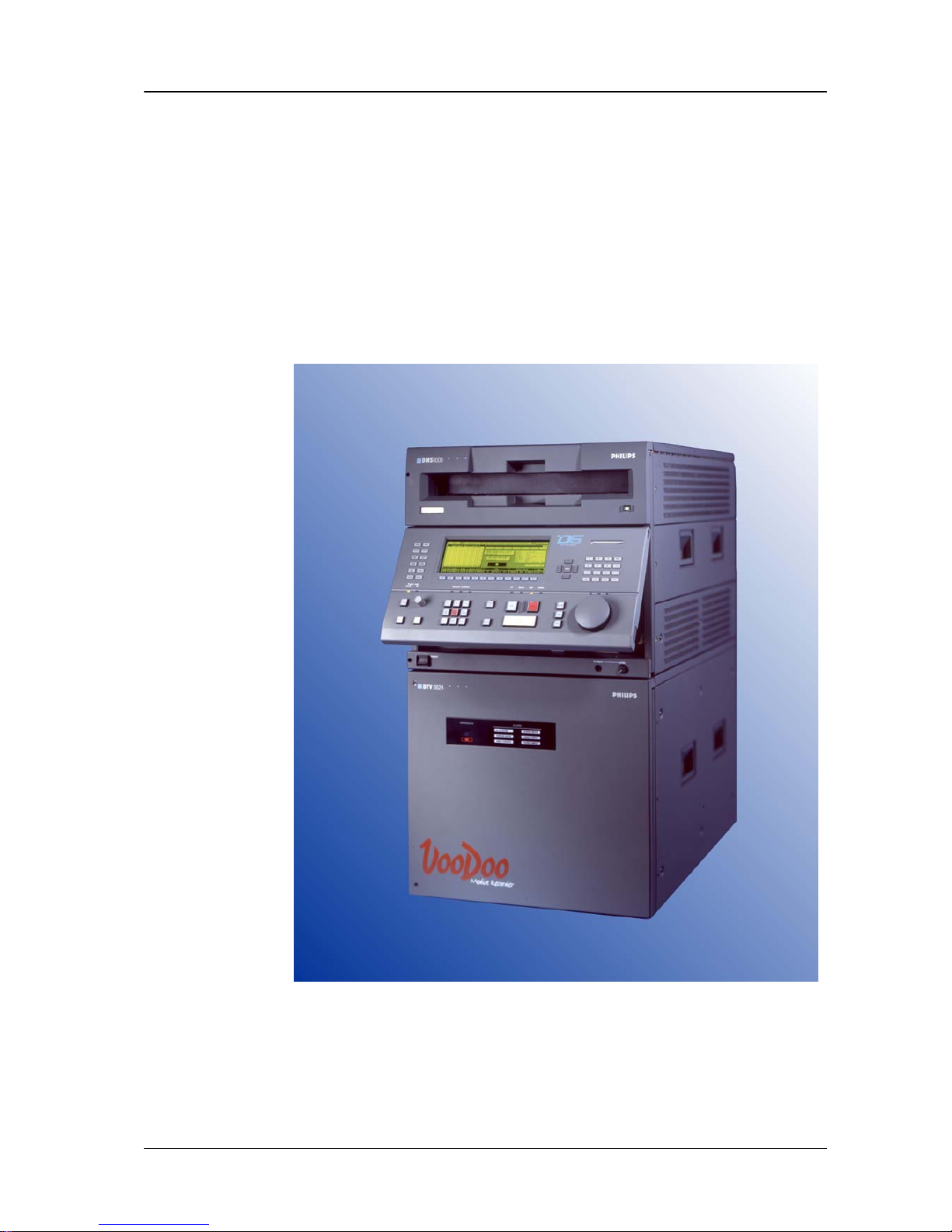
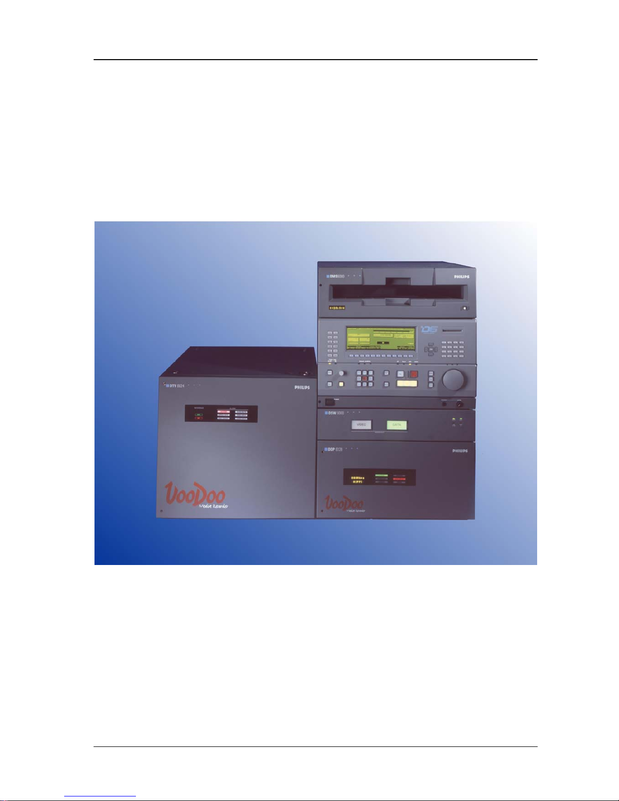
1.2.3 DFA RECORDER SYSTEM DCR 6000
The DCR 6000 consists of two basic modules:
Tapedeck DMS 6000
incl. Control Panel DCH 6024 CP
Data Processor DDP 6128
DTV Processor DTV 6024
Data Switch DSW 6000
Tapedeck
DTV
Processor
Control
Panel
Data
Processor
Data Switch
Fig. 103: DFA Recorder System DCR 6000

1. General DCR 6024/6128/6000
1 – 6
Planning and Installation – Rev. 1 / 7. 2001
1.3 MECHANICAL DESIGN
Housing The housings of the Tapedeck and Processor are made of aluminium alloy which
is coated inside with alodine to prevent electrostatic discharge influences.
Modules can be locked mechanically together and unlocked for easy transport.
19-inch rack installation kit for tapedeck and processors are available
Order no.:
BD 5197 000 175 602 211 for tapedeck
BD 5198 000 175 602 310 for DTV processor
BD 5199 000 175 602 410 for data processor
The rackmount kit for the tapedeck contains telescopic rails for easy access to
tapedeck mechanics.
Tapedeck and Processor are provided with four handles which facilitate transport
of the machine.
For service works, the Tapedeck can be hinged upwards, being hold by two locking
mechanism.

1. GeneralDCR 6024/6128/6000
1 – 7
Planning and Installation – Rev. 1 / 7. 2001
1.4 MACHINE CONTROL
The control of the DCR 6024/6128/6000 is based on a user-friendly menudriven
concept. The menus are selected via 12 dedicated keys. All menus (except Setup,
Diagnostics and Editor) are designed without any sub menus to ensure easy
handling.
The menues are application sensitive, Depending on selected modes (data or
video) and installed options there are different menues and controls available.
12 softkeys control different functions in each menu replacing a high number of
dedicated keys.
All analog adjustments are done by a digipot which function varies with the different
menus (for further informations see chapter 4 “Menu Control” in the “Operating Instructions” manual).
A unique feature for VTR’s is the availability of a credit- card sized personal card
which can be inserted in a slot on the control panel. All machine parameters and
setups accessible from the control panel can be stored on this card. Information are
stored at this card in a S-RAM buffered by a 3 V lithium battery so that it can be
loaded everywhere into the recorder. If required, the stored machine setups and
adjustments can then be recalled.

1. General DCR 6024/6128/6000
1 – 8
Planning and Installation – Rev. 1 / 7. 2001
DCR 6024/6128/6000 1. General
1 – 9
Planning and Installation – Rev. 1 / 7. 2001
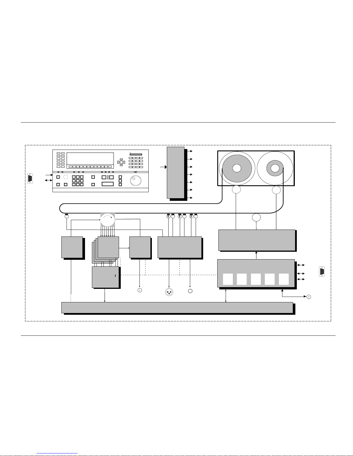
1.5 BLOCK DIAGRAM
1.5.1 TAPEDECK DMS 6000
Power
AC
M
M
M
BY 5160 SCU System Control Unit
CCUMCU TCU SIU
Servo
BY 4019
Motor Power Amplifier
Shuttle
Motor
Shuttle
Motor
Capstan
Motor
X X XX
TC
CUECTL
Main
Erase
Head
BY 5115
Cue/ CTL/ Timecode
Control Analog
TC In/Out
Head Phone
Scanner
DCH 6024 KE
BY 5113
Record
Pre–Equalizer
BY 5112
Scanner
Power
Supply
BY 5110
PLAYBACK
Equalizer
BY 5165
Clock
Recovery
WFM/Trigger
Record Data
Control
Data
Play Data
Active T erminal BoardBX 5121
REM 1
iMCS
RS232
REM 2
Diagn.
Supply
BD 5195
+44V
+15V
+13V
+5V
–2V
–5.2V
–15V
iMCS
+15V
To Processor
Fig. 104: Block Diagram Tapedeck DMS 6000
1. General DCR 6024/6128/6000
1 – 10
Planning and Installation – Rev. 1 / 7. 2001
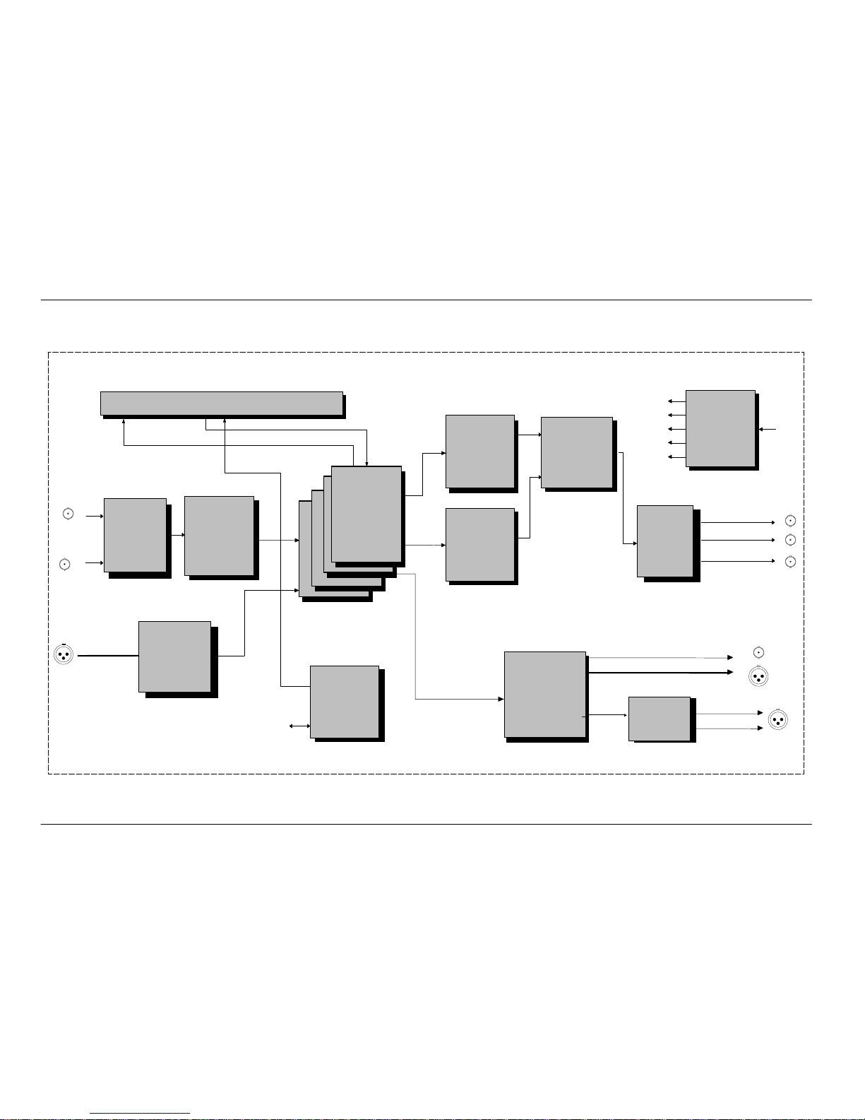
1.5.2 DTV PROCESSOR DTV 6024
I/O Buffer
Record
Data
Control Data
Play
Data
Video Digital In
(Serial)
SCCV
Scanning
Converter
VINP
Video
Input
Processor
AINP
Audio
Input
Processor
CODC – 1 – 4
Reed – Solomon
Coder/Decoder
VDFM – 1
Video
Frame
Memory
AOUT
Audio
Output
Processor
VOUT
Video
Out
Processor
SCCV
Scanning
Converter
AMON
Power
Supply
Audio Digital In
Audio Monitor Out R
SDTV Sync Out
Video Monitor Out Analog
48 kHz Out
Audio Digital Out
Audio Analog Out L
Video Digital Out Serial 1–3
SYSC
Processor
System
Control
IMCS
VDFM – 2
To Tapedeck
Video
Frame
Memory
5/6 x AES Stereo
5/6 x AES Stereo
AC IN
+/– 18V
–5.2V
+3.3V
+5V
+/– 12V
Fig. 105: Block Diagram DTV Processor DTV 6024
DCR 6024/6128/6000 1. General
1 – 11
Planning and Installation – Rev. 1 / 7. 2001
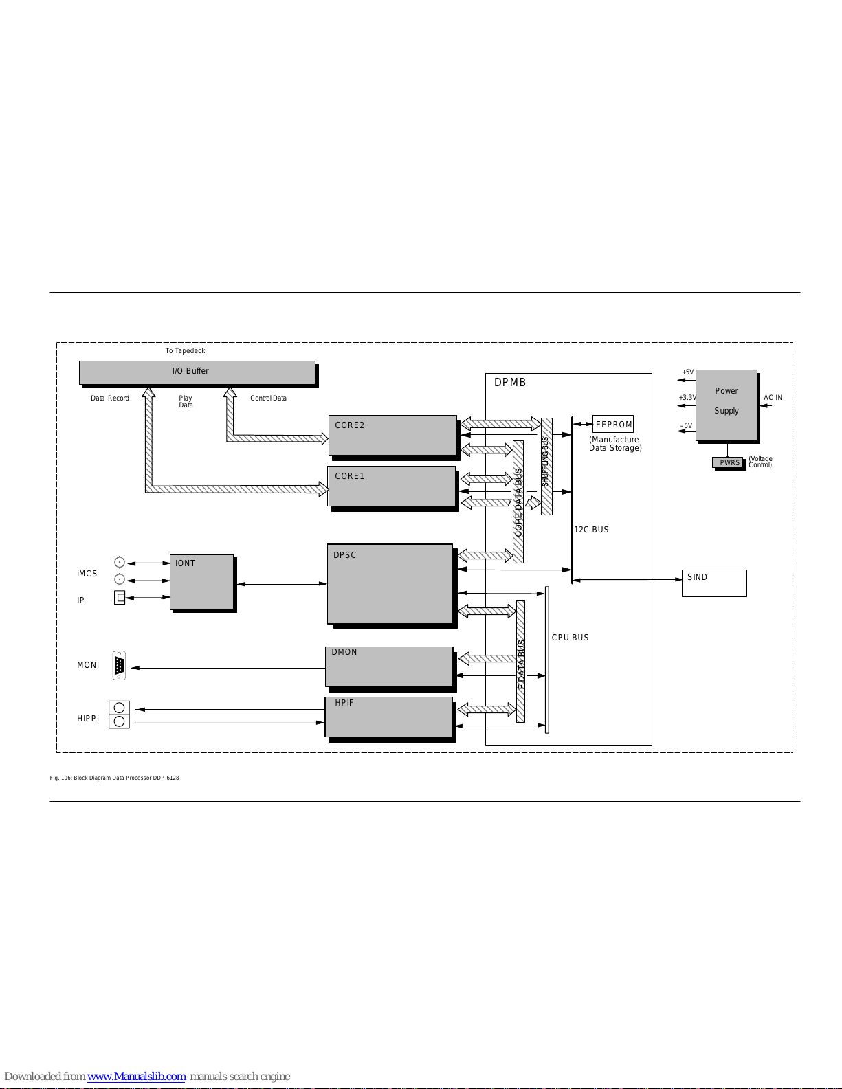
1.5.3 DATA PROCESSOR DDP 6128
I/O Buffer
RecordData Control DataPlay
Data
To Tapedeck
CORE2
HPIF
DMON
DPSC
CORE1
IONT
Power
Supply
AC IN
+5V
–5V
+3.3V
PWRS
(Voltage
Control)
ЗЗЗЗЗЗЗЗЗЗЗЗЗЗЗЗЗЗ
ЗЗЗЗЗЗЗЗЗЗЗЗЗЗЗЗЗЗ
ЗЗЗЗЗЗЗЗЗЗЗЗЗЗЗЗЗЗ
ЗЗЗЗЗЗЗЗЗЗЗЗЗЗЗЗЗЗ
ЗЗЗЗЗЗЗЗЗЗЗЗЗЗЗЗЗЗ
ЗЗЗЗЗЗЗЗЗЗЗЗЗЗЗЗЗЗ
ЗЗЗЗЗЗЗЗЗЗЗЗЗЗЗЗЗЗ
ЗЗЗЗЗЗЗЗЗЗЗЗЗЗЗЗЗЗ
ЗЗЗЗЗЗЗЗЗЗЗЗЗЗЗЗЗЗ
ЗЗЗЗЗЗЗЗЗЗЗЗЗЗЗЗЗЗ
ЗЗЗЗЗЗЗЗЗЗЗЗЗЗЗЗЗЗ
EEPROM
SIND
DPMB
(Manufacture
Data Storage)
CPU BUS
12C BUS
HIPPI
MONI
IP
iMCS
Fig. 106: Block Diagram Data Processor DDP 6128

1. General DCR 6024/6128/6000
1 – 12
Planning and Installation – Rev. 1 / 7. 2001
1. GeneralDCR 6024/6128/6000
1 – 13
Planning and Installation – Rev. 1 / 7. 2001
1.6 FUNCTIONAL OVERVIEW
For details refer to block diagram
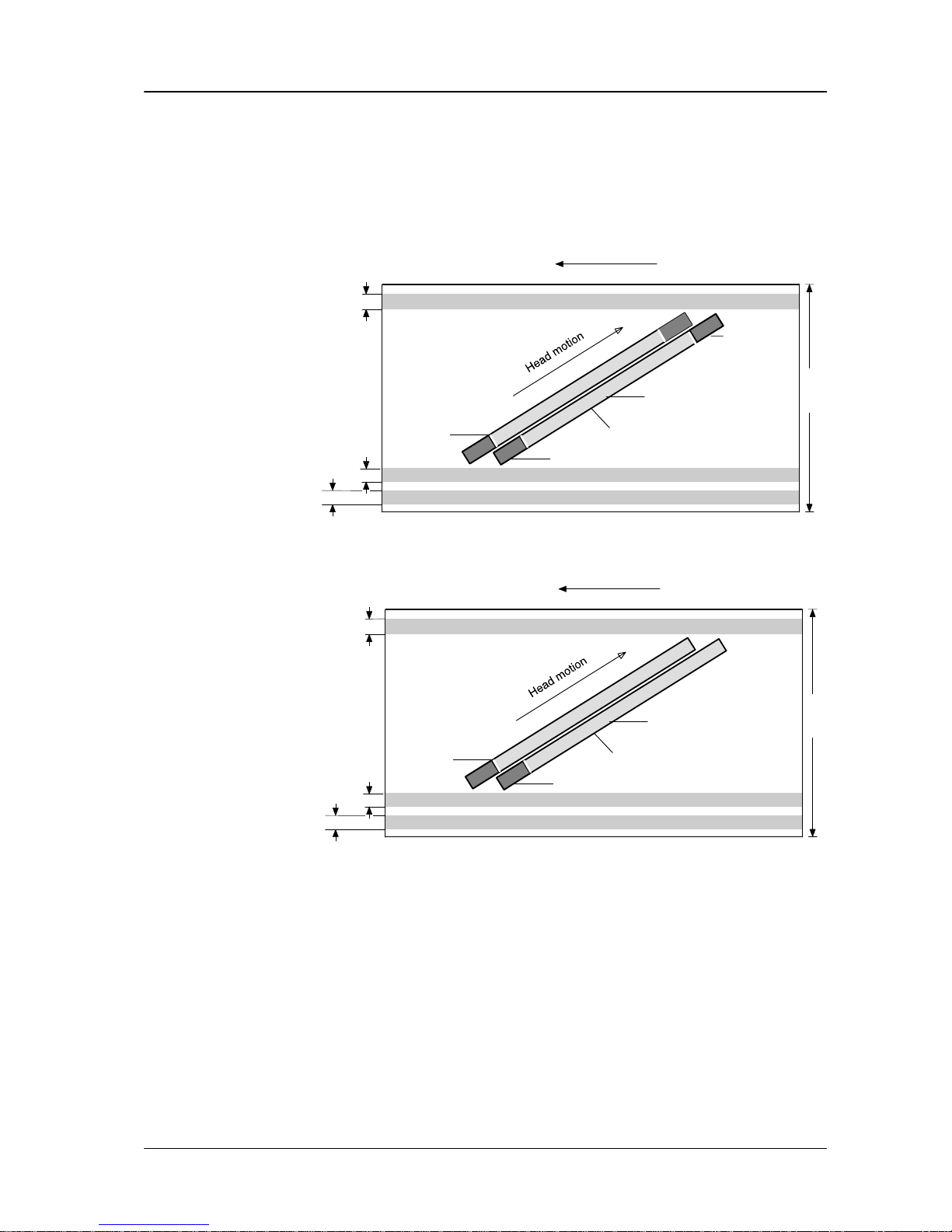
1.6.1 D–6 ST ANDARD
0,7 mm
0,5 mm
0,5 mm
19 mm
Tape motion
AUDIO CUE TRACK
CONTROL TRACK
TIME CODE TRACK
Audio sector 2nd record
Video sector
Audio sector
1st record
1 Cluster with 8 tracks
D-6
Track pattern
Video
Video/Audio gap
Fig. 107:D–6 Track pattern video
0,7 mm
0,5 mm
0,5 mm
19 mm
Tape motion
AUDIO CUE TRACK (not used)
CONTROL TRACK
Track–Set–ID and LAI (Longitudinal address information)
Rewrite area
Data sector
1 Cluster with 8 tracks
D-6
Track pattern
Data
HAI
Helical
Address
Information
Fig. 108:D–6 Track pattern data
The track pattern of the recorder contains the helical tracks with the video and audio sectors (DTV mode) and rewrite area (data mode) divided in clusters of 8 tracks
each.
It is based on azimuth recording with a track pitch of 22 m which allows a max recording capacity of 64 min or 500 GBytes with a L-type cassette.
The clusters are separated by guard bands from each other, allowing proper erasement of the individual clusters with a single flying erase head for each cluster .
One field is the minimum edit distance for video audio and data in DTV mode. It is
divided into six (24/25 Hz) or five (30 Hz) clusters respectively. In data mode the
sytem uses the 25 Hz mode internally .
Helical tracks

1. General DCR 6024/6128/6000
1 – 14
Planning and Installation – Rev. 1 / 7. 2001
In DTV mode, twelve (ten) digital audio channels are independent editable in six
(five) stereo pairs.
An edit gap between audio and video sectors allows a separate editing of audio and
video.
The audio sectors are recorded on the top (1st record) and on the bottom
(2nd record) of the helical track for additional error correction.
In data mode there is a special rewrite area at the beginning of each track. In this
area, sync blocks with detected errors during recording will be written again.
An additional Sync block located at the beginning of data area contains the HAI
(Helical Address Information). In this block all control info about the content of helical tracks like TOC (Table Of Content), and packet info is written.
One longitudinal analog audio cue track (only used in DTV mode), the control
track and the time code track complete the track configuration of the D-6 tape format.
The recorder DCR 6024 is capable of recording various progressive, “segmented
frame” or interlace standards. HD Standard (frame rate) selection is made in the
”SETUP” main menu.
The selected standard is indicated by the system status indicators at the Control
Panel, LED ”frame rate” (either 24/25 Hz or 30 Hz).
In data mode the timecode track is used to locate and identfy data and system
tracks of data recordings. On tape, a standard 25 fps SMPTE timecode is used.
For the internal control interface this information is translated into a TSID (Track
Set ID). each timecode frame is one TSID. This TSID is used for display, internal
and edit controls.
Timecode 02:00:00:00 is coverted into TSID 00000
Each new partition starts with an offset of 02:00:00:00
The UserBits contain information about type of tracks, file–no., record mode, partition–no. and tape length.
The DCR 6024 uses 1 1 µm thick D-6 tapes in three different cassette sizes S, M,
with a maximum recording time of 64min.
The magnetic tape specifications (type of cassette, tape thickness) are detected
and interpreted automatically after the cassette has been loaded.
Other 19 mm cassettes ( D-1 or D-2 type), not coded according to the D-6 format
will be rejected by the DCR 6024 recorder.
Another coding of the cassette prevents unintentional erasure of the cassette.
Use only tapes specified by Philips and Toshiba.
It uses the D-6 recording format, developed and supported by Philips Digital Video
Systems and Toshiba.
This format is based on a digital segmented-field video recording system with multichannel audio using a 19 mm cassette housing, ( S, L and M) with enhanced 11m
MP tape.The robust segmented tape format with the high sophisticated digital
Processor guarantees a reliable production and transfer recording standard for the
various standards.
D-6 Recording
format
Longitudinal
tracks
D-6 video casette

1. GeneralDCR 6024/6128/6000
1 – 15
Planning and Installation – Rev. 1 / 7. 2001
The DCR 6024/6128/6000 offers a confidence playback facility for video and audio
tape monitoring during record in DTV mode. In data mode, confidence playback is
used to check the recorded data and rewrite if necessary.
Digital recording and playback in conjunction with sophisticated error correction result in excellent picture and sound quality in DTV mode. Even after 20 tape dubbing
generations there will be no noticeable loss of quality.
The DCR 6024 includes a very powerful error correction facility with a total output
error rate of 10
-11
.
A two step error correction system, based on the Reed Solomon Code is implemented to correct data reading errors.
There are two types of errors:
Single errors
Burst errors
In data mode (DCR 6128) the error correction capabilities are increased once
more. In conjunction with a rewrite function, controlled by the result of confidence
playback functions the corrected bit error rate (BER) will be in the range of 10 E–17.
In both modes the playback quality is checkable by the ”Channel Condition” indicators (LEDs) and/or by the display of the ”ADJUST” menu.
The ”Inner-Code” is used to correct up to 7 single errors in each datablock of 227
bytes (DTV mode) or 230 Bytes in data mode.
With the restriction that the off tape bit error rate is smaller than 10
-4
and no burst
errors occur, the residual error rate after ”Inner correction” will be less than 10
-16
.
This is about one million times better than D-1 format VTR performance.
Due to scratches and tape drop outs, not only single errors but also large burst errors can occur . To overcome this problem the DCR 6024/6128 has a powerful ”Outer-Code” too.
Extensive burst errors up to 141 648 bytes of data could be corrected in DTV mode
by ”Outer correction”. That is 25 times more than a D-1 format recorder can.Using
advanced integration techniques the most powerful error correction of existing digital video standards is implemented in the DCR 6024.
In data mode (DCR 6128) the “Outer correction” is more than twice as powerful
as in DTV mode. In conjunction with the rewrite function during record the corrected
BER will be in the range of 10 E–17.
If the capacity of the error correction system is exceeded by larger defects, an error
concealment function becomes active which covers the defective data.
High quality
recording and
playback
Error Correction
Single error
correction
Burst error
correction
Concealment
(DTV–mode)

1. General DCR 6024/6128/6000
1 – 16
Planning and Installation – Rev. 1 / 7. 2001
The iMCS control interface is designed as Cheapernet-based control link (IEEE
802.3 standard) between machine(s) and control panel(s).
This interface can be used to interconnect up to four machines. Such a cluster con-
figuration allows the design of cost-effective operating configurations as only one
control panel is required to operate several machines.The integrated two-machine
editing system of the DCR 6024 uses the iMCS (2-machine cluster) as a control link
when editing with two DCR 6024.
In data mode (DCR 6128) the iMCS interface is used to control the data recorder
from telecine controllers or workstations.
iMCS

1. GeneralDCR 6024/6128/6000
1 – 17
Planning and Installation – Rev. 1 / 7. 2001
1.6.2 DTV PROCESSOR DTV 6024
Digital serial input signal is a serial data stream composed of digital samples of a
component video signal Y / PR / PB.
The signal formats for video are described in the SMPTE 274M. SMPTE 292M describes the signal parameters for serial interfaces.
The system uses an 10(8) bit quantization for Luminance and a 8 bit quantization
for chrominance.
SCCV Scanning Converter
The digital serial video input signals are fed to the board SCCV . The signal is converted from serial into parallel. Progressive signals are converted into a segmented
signal. For progressive and segmented frame modes (24, 25, 23.97 fr/sec) 2 LSB
bits from the 10 bit Y are separated and stored in a memory and inserted as lines
of the frame. In case of 8 bit signal processing and 10 bit input, a rounding process
is integrated.
VINP Video Input Processor
The selected input data are fed to the serial parallel converter and converted into
4 channel parallel luminance data (Y) and 4 channel chrominance data (Pb/Pr).
After line shuffling, parity bytes for the outer error correction coding are added.
CODC 1-4 Inner Coder/Decoder
The coded data are fed to the board CODC. On this board, the coded data are further shuffled in a field basis.
After mixing with the audio data, parity bytes for the inner error correction coding
are added.
In the channel encoder, the eight bits data are transformed into 12 bits data, then
the sync words are added.
A head delay compensates for the timing difference between each channel,
caused by the difference of the mechanical position of each head on the headwheel.
Finally, the data are converted to serial data (8 channel record data, 2 bit parallel),
and sent to the Tapedeck as ”record data” via the buffer board I/O1.
The digital audio interface meets the AES-/EBU- standard AES 3, 1992.
A total of 12 (10) channels or 6 (5) stereo pairs is available for the digital recording
of audio signals, it uses a sampling frequency of 48 kHz and 20 to 24 bit linear quantization.
Digital Video
Interfaces
Video Record
AES-/EBUStandard

1. General DCR 6024/6128/6000
1 – 18
Planning and Installation – Rev. 1 / 7. 2001
AINP Audio Input
The recording signals are fed to the board AINP. The segment memory stores the
recording signals temporarily to establish the segmented recording signal format,
which corresponds to the audio data block for error correction coding. Readout signal from the segment memory is supplied to the Read-Solomon encoder which calculates outer parities for the audio data. The encoded output signal is stored in the
shuffling memory. This memory generates the first and the second recording data
with different shuffling schemes in a unit of inner code word.
The first and second recording data are transmitted to the board CODC to be multiplexed into video data.
CODC Encoder / Decoder
The serial data are fed to the decoder board CODC via the board I/O1 from the Tapedeck. In this board, the serial data are converted into parallel form, and fed to
the TBC (Time Base Corrector) to reject time base errors. The sync pattern are detected from the reproduced data in the sync detector circuit. The channel decoder
converts the 12-bit modulated data into 8-bit data. The inner decoder performs
detection and correction of errors. The audio data are separated after inner error
correction.
VDFM Video Playback Processor
In the board VDFM, the field deshuffling is done in a field basis, then the outer error
correction is carried out.
VOUT Video Out Processor
The corrected data are fed to the board VOUT. In the board VOUT, the data is rearranged into the original data arrangement after the line deshuffling and channel
deshuffling.The concealment circuit is provided to interpolate the data in case that
the data are not fully corrected by using the outer parity. By using the surrounding
non-erroneous pixels the erroneous data are interpolated. The video sync data are
added to the blanking interval then the data are converted from parallel form to serial form, and fed to the board SCCV. If the digital I/O option (available only for 60i
and 59.94i) is installed the digital signal is fed to the output connector.
SCCV Scanning Converter
The digital parallel signal coming from the VOUT board is converted from a segmented format to the selected output format. Lines containing 2bit Y are stored
in a memory and added to the Y signal. A parallel to serial converter generates the
output signal according to SMPTE 292M standard.
A video monitoring circuit generates an analog output signal (Y, PR, PB, Sync) or
R, G, B, Sync according to the selected standard.
AOUT Audio Out Processing
The board CODC supplies reproduced audio data to the board AOUT .In the board
AOUT, the reproduced data and inner decoder flags are stored in the deshuffling
memory. Storing operation is permitted when the reproduced data are likely to have
correct inner code block addresses. When the storing is inhibited, a new/old flag
is set to ”1” for corresponding inner code block in order to avoid misdetection by
older correct inner code block.The first and the second recording data are readout
from the deshuffling memory by turns in a unit of symbol. Then, for each data symbol, optimum one is selected to achieve optimum outer code word. This code word
Audio Record
Video Play
Audio Play

1. GeneralDCR 6024/6128/6000
1 – 19
Planning and Installation – Rev. 1 / 7. 2001
is fed to the Reed-Solomon decoder for error detection and correction. The decoded output data are stored in the segment memory to get an audio data sequence. The error concealment and the level control are applied to this sequence.
(AES/EBU interface encoding is applied to the audio data, and the encoded data
are output through rear panel connectors as audio digital output signals)
Analog Audio Option, Audio Monitoring Option
Two channels are available on the audio monitor output through the output connectors of the rear panel and the headphone jack in the Tapedeck.The monitor signals
can be selected from the input or reproduced audio signals, the aux input signal,
the cue record signal and the cue playback signal.
The SYSC board consists of System Control block and Sync Generator block. The
System Control block controls the system, communicates with the Tapedeck and
outputs superimpose data. The sync generator block consists of a diverse sync
signal generator, a system clock regenerator, a playback sync signal phase adjuster, a NTSC / PAL sync signal generator and a channel clock generator circuits.
The timing of every synchronizing signal is completely switchable to meet each HD
standard.
System Control

1. General DCR 6024/6128/6000
1 – 20
Planning and Installation – Rev. 1 / 7. 2001
1.6.3 DA TA PROCESSOR DDP 6128
To prevent major modifications in the tapedeck, one of the existing video modes
is for data recording. When in data mode, the tapedeck runs internally in a video
mode (50Hz). So all tapedeck functions like servos, timecode units can be remained unchanged. Only the system software has to be modified for data version.
HPIF Board (HIPPI–Interface)
The optical signal is fed from the input to this board. This board is responsible for
communication with external Hippi devices. A conversion from optical serial signal
to electrical parallel signal is made. A buffer of 128 MBytes allows a flexible handling of incoming data stream. The Hippi header is detected and analyzed. The
header is removed and the data is provided to DPSC board.
DPSC Board
On the DPSC board the internal data controls are processed. Control information
like helical address information (HAI), table of content (TOC), partition information
(PSIT) is generated and inserted in data stream. All required clock generators are
located on this board. The incoming data packet is distributed and segmented into
8 channels.
This board contains also the system control unit.
CORE Board
This board is responsible for the standard digital recorder signal processing steps.
The functions are comparable with the CODC board of the DTV processor. Each
board contains 4 channels, so two identical boards are used in the data processor.
The Reed Solomon error correction encoder adds check bytes to the data bytes.
A rewrite memory stores data and inserts this data again if a rewrite due to error
rate is required.
After channel coding and conversion from parallel to 2bit serial mode, the data is
fed to the tapedeck.
CORE Board
The playback data stream (8channels) is fed to the two boards. Similar functions
compared to the CODC board are implemented:
Channel decoding
Sync detection
Error detection and correction.
For the rewrite function, a error information for rewrite decision is generated.
DPSC Board
The DPSC board extracts and processes all control information that was inserted
in the data stream during record (HAI, TOC). The data signal is combined from the
8 channels.
Record Path
Play Path

1. GeneralDCR 6024/6128/6000
1 – 21
Planning and Installation – Rev. 1 / 7. 2001
HPIF Board
The playback data signal is prepared for Hippi transfer. signal information (size) is
analyzed and a Hippi header is generated. Communication with Hippi destination
device is started and data is sent via optical transceiver. For playback mode the
same buffer memory of 128 MBytes is used.
DPX Monitoring (Option)
If the incoming / outgoing data stream is detected as DPX data, the signal is fed
to the DPX monitoring board. This board is located on the HPIF –board. The out
put of this board is a standard XGA signal (1024x768 / 80Hz). The DPX data is converted into an XGa signal. If the resolution of DPX signal is lower than XGA resolution, the complete picture is displayed. If the resolution is higher, the resolution is
reduced by skipping lines and pixels. Because this is only a monitoring feature
boarders may appear on the screen depending on DPX resolution.
In record mode, this board is connected to the input data stream, inplayback mode,
the board is connected to the output data stream.
DPCU System Control
The system control is responsible for the control of all boards and the communication with tapedeck via iMCS. For service mode a RS232 serial port is installed. Software updates can be done using this port to reprogram the flash Eproms.
 Loading...