

Vonsch Unifrem Series, Unifrem 400, Unifrem 230 M, Unifrem 400 M, Unifrem 500 Configuration And Diagnostics
...
10 May 2017 Page 1 from 180
Configuration and diagnostics
for UNIFREM and QUATROFREM (output side)
frequency converters

UNIFREM v.3.41x
10 May 2017 Page 2 from 180

UNIFREM v.3.41x
10 May 2017 Page 3 from 180
1 Contents
2 Structure and types of parameters in the document .................................................................... 7
2.1 Defining the meaning and type of parameters in part DIAGNOSTICS ................................ 7
2.2 Defining the meaning and type of parameters in part SETTINGS ....................................... 8
2.3 Type of parameters defining in the part SAVE / RESTORE .............................................. 13
3 Range of parameters by product type ........................................................................................ 14
3.1 Undervoltage, overvoltage .................................................................................................. 14
3.2 Temperatures ...................................................................................................................... 14
4 DIAGNOSTICS ........................................................................................................................... 15
4.1 Command ............................................................................................................................ 15
4.2 Control ................................................................................................................................. 15
4.2.1 Power and energy ........................................................................................................ 16
4.2.2 Additional quantities ..................................................................................................... 16
4.2.3 Positioning .................................................................................................................... 17
4.3 Inputs and outputs ............................................................................................................... 17
4.3.1 BIN................................................................................................................................ 17
4.3.2 AIN................................................................................................................................ 17
4.3.3 RELAYS ....................................................................................................................... 18
4.3.4 AOUT ........................................................................................................................... 18
4.3.5 IRC1,IRC2,ARC ........................................................................................................... 19
4.4 Functions ............................................................................................................................. 20
4.4.1 PLC function ................................................................................................................. 20
4.4.2 Limit switches ............................................................................................................... 21
4.4.3 Process controller ........................................................................................................ 21
4.4.4 Optimization ................................................................................................................. 22
4.4.5 Lifting functions ............................................................................................................ 22
4.4.6 Pantograph ................................................................................................................... 22
4.4.7 Ext. thermal protection ................................................................................................. 23
4.4.8 Differential .................................................................................................................... 23
4.5 Converter state .................................................................................................................... 23
4.6 Thermal protections ............................................................................................................. 24
4.7 Communication.................................................................................................................... 25
4.7.1 MODBUS ...................................................................................................................... 25
4.7.2 PROFIBUS ................................................................................................................... 25
4.7.3 RS LINKS ..................................................................................................................... 26
4.8 SW and HW version ............................................................................................................ 26
4.9 Date and Time ..................................................................................................................... 27
5 WARNINGS ................................................................................................................................ 28
6 ERRORS ..................................................................................................................................... 32
7 SETTINGS .................................................................................................................................. 35
7.1 Using the quick setup wizard with VONSCH UNIFREM .................................................... 35
7.1.1 Working with the wizard ............................................................................................... 35
7.1.2 Steps of the quick setup wizard ................................................................................... 36
7.1.3 Setting the motor data, application and command macro ........................................... 37
7.1.4 Application macros ....................................................................................................... 38
7.1.5 Command macros ........................................................................................................ 39
7.1.6 Directions and the encoder .......................................................................................... 40
7.1.7 Control methods, parameter identification, dynamics of the drive .............................. 41
7.2 MOTOR ............................................................................................................................... 42
7.2.1 MOTOR MACROS ....................................................................................................... 43
7.2.2 IDENTIFICATION......................................................................................................... 43
7.2.3 NAMEPLATE MOTOR PARAMETERS....................................................................... 44
7.2.4 SPECIAL PARAMETERS OF THE MOTOR ............................................................... 45
7.3 CONVERTER PARAMETERS ............................................................................................ 47
7.3.1 APPLICATION MACROS ............................................................................................ 47

UNIFREM v.3.41x
10 May 2017 Page 4 from 180
7.3.2 ENERGY CONS........................................................................................................... 48
7.4 COMMANDS ....................................................................................................................... 48
7.4.1 COMMAND MACROS ................................................................................................. 48
7.4.2 START STOP RESET ................................................................................................. 49
7.4.3 FREQUENCY SETPOINT ........................................................................................... 51
7.4.4 TORQUE SETPOINT ................................................................................................... 52
7.4.5 POSITION SETPOINT ................................................................................................. 53
7.4.6 DISCRETE SETPOINTS ............................................................................................. 54
7.4.7 UP/DOWN COMMANDS ............................................................................................. 56
7.4.8 AUTO OFF ................................................................................................................... 56
7.5 CONTROL AND REGULATION ......................................................................................... 57
7.5.1 CONTROL METHOD ................................................................................................... 57
7.5.2 V/f CONTROL .............................................................................................................. 58
7.5.3 VECTOR CONTROL ................................................................................................... 62
7.5.4 FREQUENCY RAMPS ................................................................................................. 69
7.5.5 MAXIMUM CURRENT AND VOLTAGE ...................................................................... 71
7.5.6 FLYING START ........................................................................................................... 71
7.5.7 VOLTAGE CONTROLLER (VC) .................................................................................. 72
7.5.8 BRAKE MODULE......................................................................................................... 73
7.5.9 FLUX BRAKING ........................................................................................................... 74
7.5.10 POWER RESTRICTION .............................................................................................. 74
7.6 INPUTS AND OUTPUTS .................................................................................................... 75
7.6.1 BINARY INPUTS.......................................................................................................... 75
7.6.2 ANALOG INPUTS ........................................................................................................ 76
7.6.3 RELAY OUTPUTS ....................................................................................................... 80
7.6.4 ANALOG OUTPUTS .................................................................................................... 82
7.6.5 IRC1 ............................................................................................................................. 84
7.6.6 IRC2/ARC..................................................................................................................... 85
7.7 FUNCTIONS ........................................................................................................................ 85
7.7.1 PLC FUNCTIONS ........................................................................................................ 85
7.7.2 LIMIT SWITCHES ........................................................................................................ 95
7.7.3 PROCESS CONTROLLER .......................................................................................... 97
7.7.4 OPTIMIZATION .......................................................................................................... 100
7.7.5 MECHANICAL BRAKE .............................................................................................. 102
7.7.6 LIFTING FUNCTIONS ............................................................................................... 102
7.7.7 EXTERNAL THERMAL PROTECTION (ETP) .......................................................... 105
7.7.8 IRC1,2 DIFFERENCE ................................................................................................ 106
7.7.9 DIFFERENTIAL .......................................................................................................... 107
7.8 FAULTS AND WARNINGS ............................................................................................... 107
7.8.1 OPTIONAL FAULTS .................................................................................................. 107
7.8.2 ENC. FAULTS ............................................................................................................ 109
7.8.3 FAULT ACKNOWLEDGEMENT ................................................................................ 109
7.8.4 QUANTITIES TO LOG ............................................................................................... 110
7.8.5 WARNINGS ............................................................................................................... 111
7.9 DISPLAY............................................................................................................................ 112
7.9.1 DISP. QUANT. SETTINGS ........................................................................................ 112
7.9.2 MONITOR SETTING ................................................................................................. 112
7.10 COMMUNICATION ........................................................................................................... 112
7.10.1 MODBUS .................................................................................................................... 113
7.10.2 PROFIBUS ................................................................................................................. 115
7.11 PAR. SETS ........................................................................................................................ 117
7.11.1 SET SWITCH ............................................................................................................. 117
7.11.2 USER SETS ............................................................................................................... 118
8 Converter function configuration manual ................................................................................. 128
8.1 Production (factory) settings ............................................................................................. 128
8.2 Motor parameters – MOTOR MACROS – identification ................................................... 128
8.3 Motor control modes .......................................................................................................... 129

UNIFREM v.3.41x
10 May 2017 Page 5 from 180
8.3.1 V/f control ................................................................................................................... 130
8.3.2 V/f curve ..................................................................................................................... 131
8.3.3 IR compensation ........................................................................................................ 133
8.3.4 Starting Torque Controller (STC) ............................................................................... 134
8.3.5 Slip compensation ...................................................................................................... 135
8.4 Maximal current controller (MCC) ..................................................................................... 136
8.5 Resonance damping ......................................................................................................... 139
8.6 Voltage controller (VC) - Dynamic deceleration (DD) a Kinetic backup (KB). ................. 141
8.7 Flux braking ....................................................................................................................... 143
8.8 Flying start ......................................................................................................................... 144
8.9 Power restriction ................................................................................................................ 145
8.10 Optimization ....................................................................................................................... 146
8.11 External thermal protection (ETP) ..................................................................................... 149
8.12 Overload switch „OPS“ ...................................................................................................... 151
8.13 Dynamic lift (DL) function .................................................................................................. 154
8.14 IRC detuning function ........................................................................................................ 156
8.15 Using the parameter set switching for a special behavior of converter functions ............ 158
9 UNIFREM Frequency converter settings examples ................................................................. 162
9.1 Process controller - PC setting to control the level height in the tank .............................. 162
9.1.1 Situation ..................................................................................................................... 162
9.1.2 Converter connection ................................................................................................. 162
9.1.3 Analog inputs setting .................................................................................................. 162
9.1.4 Process controller setting........................................................................................... 162
9.1.5 Converter output setting............................................................................................. 163
9.1.6 Monitoring................................................................................................................... 163
9.2 Example of logical blocks setting ...................................................................................... 164
10 Control panel – Unipanel user manual ................................................................................. 169
10.1 Buttons............................................................................................................................... 169
10.2 Panel start ......................................................................................................................... 170
10.3 Display ............................................................................................................................... 170
10.4 Converter status ................................................................................................................ 170
10.5 Main menu F1.................................................................................................................... 170
10.6 Monitor, monitor detail ....................................................................................................... 173
10.7 Parameters setting ............................................................................................................ 174
10.8 Graph ................................................................................................................................. 177
10.9 Parameter search .............................................................................................................. 179
10.10 Device selection for control panel ................................................................................. 180

UNIFREM v.3.41x
10 May 2017 Page 6 from 180
WARNING
This manual dedicates to the parameters and options of VONSCH UNIFREM frequency converter
settings and diagnostics.
UNIFREM v.3.41x
10 May 2017 Page 7 from 180
2 Structure and types of parameters in the document
2.1 Defining the meaning and type of parameters in part DIAGNOSTICS
Diagnostic parameter that displays the value of signal in physical units or in relative units or
discrete number of sequences, steps, received data etc.
EXAMPLE:
Value – the value
MENU \ DIAGNOSTICS \ Converter state \
Value – discrete number
MENU \ DIAGNOSTICS \ Functions \ Lifting functions\
Example for value diagnostics – the value display
Example of diagnostic value representing the number
of illegal control drive sequences
Individual word bits status diagnostics. Each bit represents the status of one flag of a specific
function or converter mode.
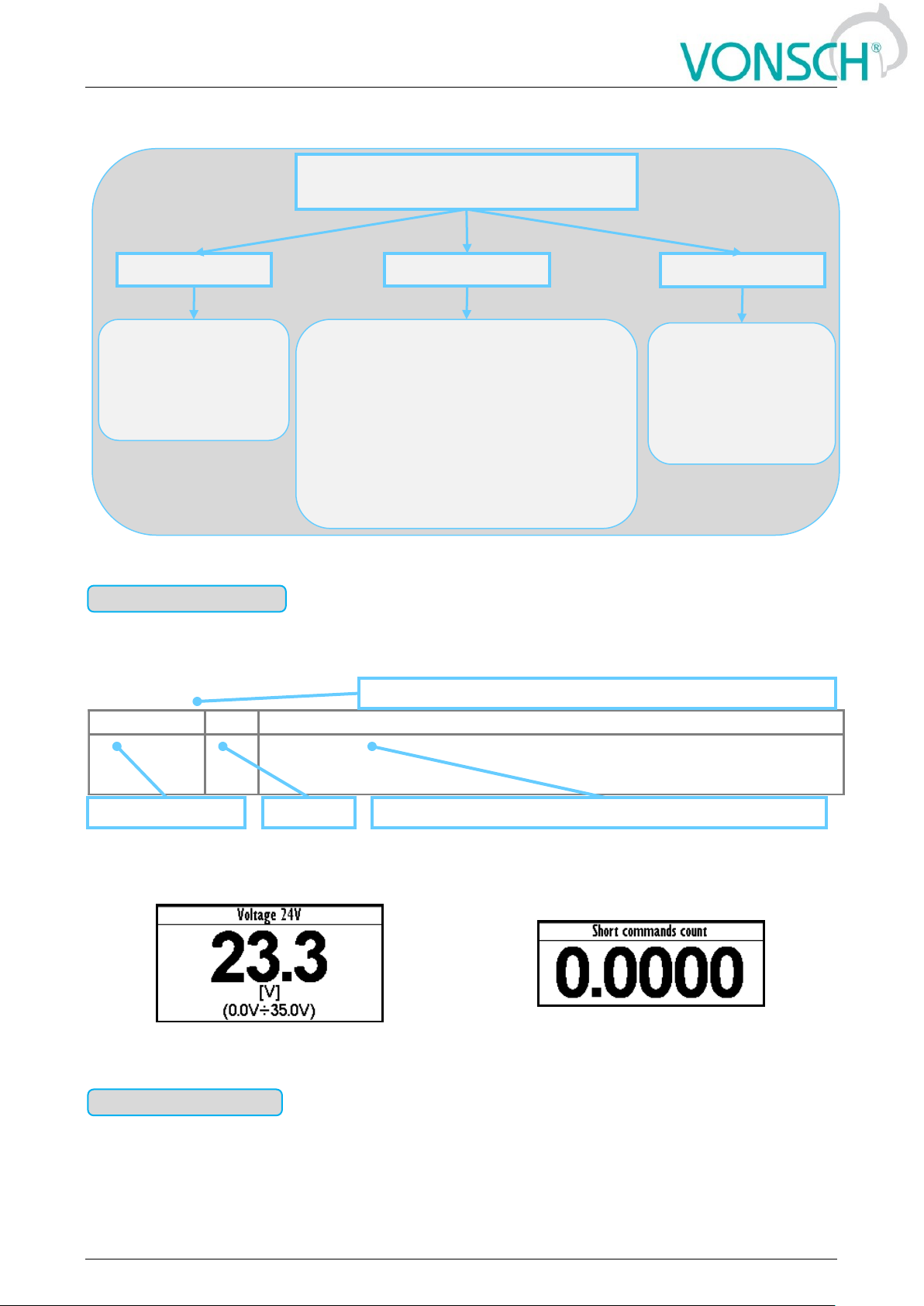
MENU PARAMETERS
ID – unique identification number
SETTINGS
DIAGNOSTICS
SAVE/RESTORE
-Value–the value,
number
-Word (array of bits)
-Constant
-Date time
-The value
-Calculated parameters
-Selection (1 option selection)
-Multiple selection (multiple options
selection - mask)
-Command (execution of a single action)
-Signal (source of signal and functions
inputs)
-Dynamic value (linked parameter)
-Password
-Path (position in the
structure of
parameters)
-parameters types as
in the part
SETTINGS
Parameter type: VALUE
Name [ID]
Unit
Description
AIN1 Rel.
[41]
%
Value of the signal connected to the analog input terminals + X1:11 and X1:12.Parameters of the analog input can be configured in the parameter group
P[147] AIN1.
MENU \ DIAGNOSTICS \ Inputs / outputs \ AIN \
Value unit
Values ID and name
The basic diagnostics information about the importance of value
Position of the parameter in a tree hierarchical parameters structure
Parameter type: WORD

UNIFREM v.3.41x
10 May 2017 Page 8 from 180
EXAMPLE:
MENU \ DIAGNOSTICS \ Command \
MENU \ DIAGNOSTICS \ Inputs / outputs \ Relay
Converter control signals diagnostics
Output relays status diagnostics
Diagnostic information, which takes a fixed value.
EXAMPLE:
Constant
Diagnostic value of the date or time format.
MENU \ DIAGNOSTICS \
MENU \ DIAGNOSTICS \
2.2 Defining the meaning and type of parameters in part SETTINGS
Possibility of parameter value setting in absolute or relative units.
Name [ID]
Unit
Description
OPS status [856]
Indicates the status of the OPS switch block.
Reset
RESET signal of the OPS is active.
Detection
Autodetection of the overload limits is running.
Overload
Overload occurred. Operation in the positive direction (up) is blocked.
Tipping
Too many forbidden tipping control commands.
Settling
Drive operates in static mode.
Dynamics
Drive operates in dynamic mode.
MENU \ DIAGNOSTICS \ Functions \ Lifting functions\
The basic diagnostic information about the importance of word
Additional diagnostic information about word bits view, status of
word bits view, respectively meaning of word bits
Individual word bits
description
Parameter type: CONSTANT
Name [ID]
Unit
Description
SW Version [379]
Converter SW version
MENU \ DIAGNOSTICS \ SW and HW version \
Constant description
Parameter type: DATE TIME
Parameter type: THE VALUE

UNIFREM v.3.41x
10 May 2017 Page 9 from 180
EXAMPLE:
MENU \ SETTINGS \ MOTOR \
Motor current value setting
Nominal motor voltage value setting
Parameter, that is derived by calculation based on the values of other parameters.
EXAMPLE:
MENU \ SETTINGS \ MOTOR \ SPECIAL PARAMETERS \
Example of the calculated parameter
Name [ID]
Description
Def.
Nom. Current
[151]
Nominal motor current, read from the nameplate or catalog data.
2.80 A
0.01 A ÷ 1000.00 A
This parameter determines the value of permanent motor current for motor
overload protection P[27] Motor overloading.
MENU \ SETTINGS \ MOTOR \
Basic information about the importance of the parameter
Range of the value, that
parameter can take Min ÷ Max
Additional information
about the importance of the
parameter
The default value of the parameter –
The value that is set at factory settings
restoration
Parameter type: CALCULATED PARAMETER
Name [ID]
Description
Def.
Nr of motor poles [1049]
Number of motor poles calculated from the nominal rpms and the motor
frequency.
2 ÷ 1000
MENU \ SETTINGS \ MOTOR \ SPECIAL PARAMETERS \
Additional information about derivation of parameter calculation
UNIFREM v.3.41x
10 May 2017 Page 10 from 180
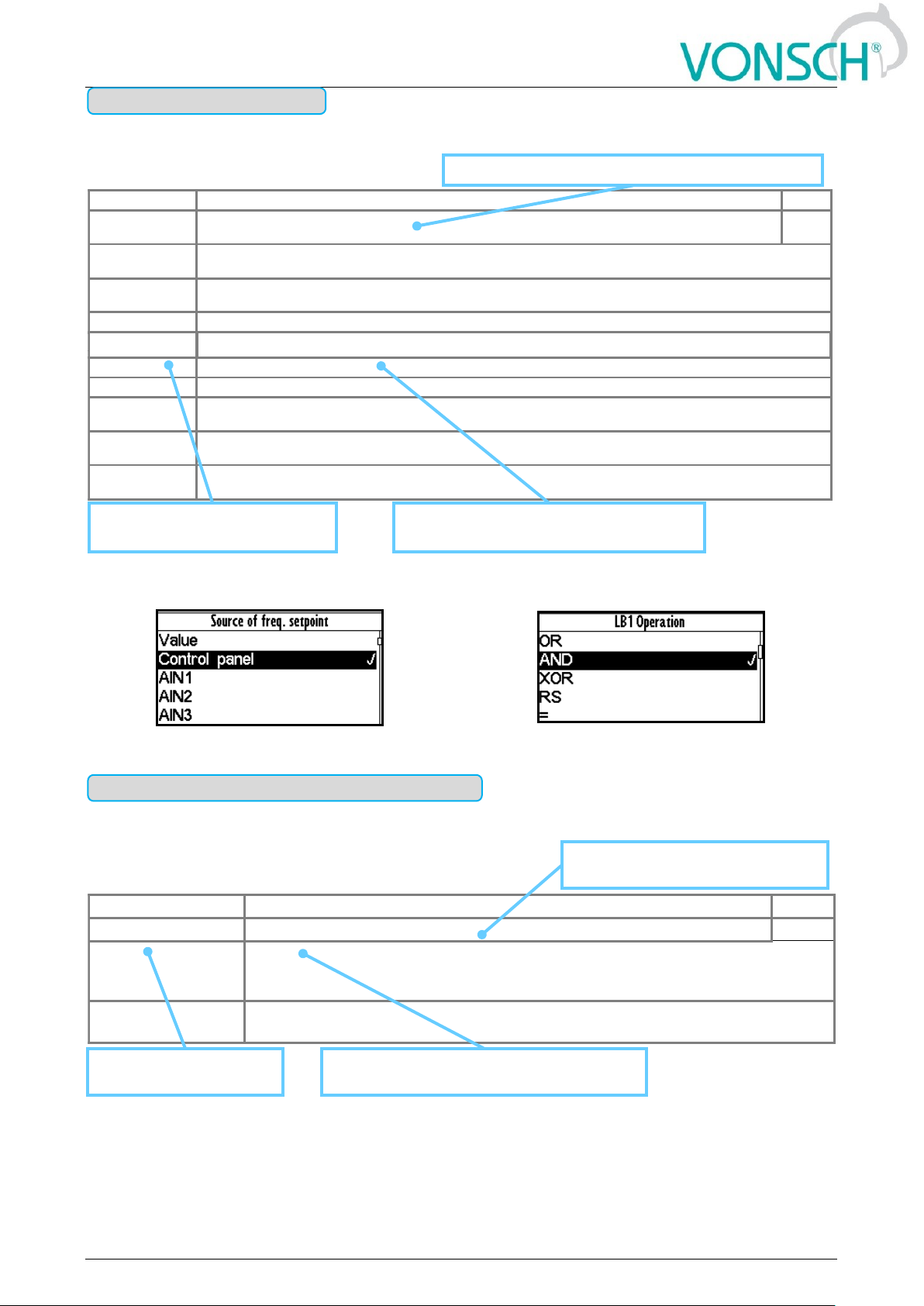
Type of parameter with option to select only one setting option (alternative).
EXAMPLE:
MENU \ SETTINGS \ COMMANDS \ FREQUENCY SETPOINT \
... \ SETTINGS \ FUNCTIONS \ LOGICAL BLOCKS\ LB1 (Fast) \
One setting option selection of selection type parameter examples
Parameter type with a option to select multiple possible value elections, modes, respectively active
bit of parameter.
Parameter type: SELECTION
Name [ID]
Description
Def.
Start source
[194]
Setting the converter start source. The START command generates the desired voltage and frequency
on the U,V,W outputs (or U,V for a single phase load).
BIN1
Control panel
Pressing the green START button on the control panel causes the converter to start. The start is canceled by
pressing the red STOP button.
Permanent
start
The converter starts immediately after the switch on.
BIN1
The converter start after the activation of the 1st binary input.
BIN5
The converter starts after the activation of the 5th binary input.
BIN6
The converter starts after the activation of the 6th binary input.
MODBUS
The converter start is controlled over the serial communication. See the MODBUS serial communication
protocol.
PROFIBUS
The converter start is controlled over the serial communication. See the PROFIBUS serial communication
protocol.
Special
The converter start is controlled by a special preset signal and switching thresholds, see P[987] SPECIAL
START.
MENU \ SETTINGS \ COMMANDS \ START STOP RESET \
Basic information about type of parameter - selection
The name of specific (alternative)
selection of parameter value
Additional information about the meaning
of a specific parameter selection
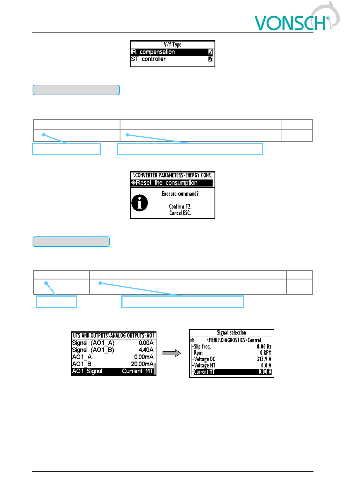
Parameter type: MULTIPLE SELECTION (MASK)
Name [ID]
Description
Def.
V/f Type [347]
V/f Curve type. Selecting the features of the V/f control method operation.
□ IR compensation
Turns on the stator resistance loss compensation P[973] Compensation of IR
(CIR). Requires correct value of the motor parameters and the stator resistance
P[345] Stator resistance.
□ ST controller
Turns on the starting torque controller P[29] ST Controller (STC) to boost starting
torque.
* When the square is black ■ - the default setting is set
MENU \ SETTINGS \ CONTROL AND REGULATION \ V/f CONTROL \ V/f CURVE \
Basic information about the
parameter type - multiple selection
Names of parameter
value elections (modes)
Additional information about the meaning of
individual parameter elections (modes)
UNIFREM v.3.41x
10 May 2017 Page 11 from 180
EXAMPLE:
Example: V/f curve operation mode selection
Command to execute a single action or operation on the converter. It is required to confirm the
command before execution in the confirmation window.
EXAMPLE:
This command resets consumed energy counters
Parameter for dynamic ties and any parameter connection, that becomes a value source for a
given function or for input of this function.
EXAMPLE:
MENU \ SETTINGS \ INPUTS AND OUTPUTS \ ANALOG OUTPUTS \ AO1 \
Selection of the signal that will linearly recalculate the analog output AO1
Parameter type: COMMAND
Name [ID]
Description
Def.
Reset the consumption [897]
This command resets the counters of consumed energy.
MENU \ SETTINGS \ CONVERTER PARAMETERS \ Energy consumption \
Function, description and importance of the command
Name and command ID
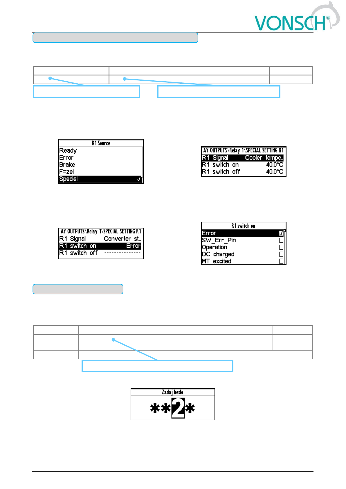
Parameter type: SIGNAL
Name [ID]
Description
Def.
AIN1 Signal [251]
Selection of the signal that will be linearly recalculated according to the
analog input.
[ - ]
MENU \ SETTINGS \ INPUTS AND OUTPUTS \ ANALOG INPUTS \ AIN1 \ SPECIAL SETTING \
Type of signal selection from the diagnostics
Signal name
UNIFREM v.3.41x
10 May 2017 Page 12 from 180
Parameter is dynamically set to the value that is inherited from another parameter (usually from the
signal type parameter).
EXAMPLE:
The condition for RELAY switching „R1 switch on [301]“ – If any parameter (e.g. Cooler
temperature [74]) is selected as „R1 Signal [189]“:
MENU \ SETTINGS \ INPUTS AND OUTPUTS \ RELAY
OUTPUTS \ Relay 1 \
MENU \ SETTINGS \ INPUTS AND OUTPUTS \ RELAY
OUTPUTS \ Relay 1 \ SPECIAL SETTING R1 \
Special source of Relay R1 switch setting
Relay R1 switches on when heatsink temperature
exceeds the set level
The condition for RELAY switching „R1 switch on [301]“ – If status word is selected as „R1 Signal
[189]“:
MENU \ SETTINGS \ INPUTS AND OUTPUTS \ RELAY OUTPUTS \ Relay 1 \ SPECIAL SETTING R1 \
Relay R1 switches on at active bite (Failure) of converter status word
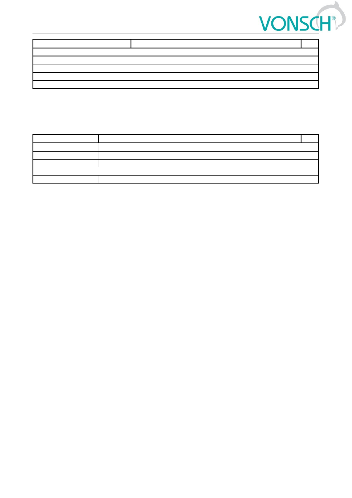
Parameter to enter a password to allow access to the specific levels of converter setting
respectively to unlock some of the modes.
The password characters can be {0..9, A..Z}.
EXAMPLE:
Example of password entry
Parameter type: DYNAMIC VALUE (Linked parameter)
Name [ID]
Description
Def.
R1 switch on [301]
Conditions for R1 switch on.
Run |
MENU \ SETTINGS \ INPUTS AND OUTPUTS \ RELAY OUTPUTS \ Relay 1 \ SPECIAL SETTING \
Name and ID of the dynamic parameter
Default value of the dynamic value parameter
Parameter type: PASSWORD
Name [ID]
Description
Def.
Password
[548]
Setting the user password for access to the device settings. Password
needs to be entered when entering the converter settings.
0 *
0 * ÷ 0 *
Protects the converter settings against reconfiguration by unauthorized persons.
MENU \ SETTINGS \ CONVERTER PARAMETERS \
Basic information about the importance of the parameter

UNIFREM v.3.41x
10 May 2017 Page 13 from 180
UNIPANEL – PASSWORD SETTING
Set the required password character:
Cursor position change:
After setting the password, press ENTER to confirm.
2.3 Type of parameters defining in the part SAVE / RESTORE
Parameter of root parameters directory choice defining.
EXAMPLE:
INPUTS AND OUTPUTS root directory selection for the transfer of parameters from set 1 to set 3
Parameter type: PATH
Name [ID]
Description
Def.
Directory [ - ]
The choice of which part of the parameters will be restored. If nothing
is selected, all will be restored.
INPUTS AND
OUTPUTS
0 * ÷ 0 *
MENU \ SAVE / RESTORE \ Parameters backup \ Parameter transfer \
Basic information about the importance of the parameter
The selected path in the tree hierarchy
UNIFREM v.3.41x
10 May 2017 Page 14 from 180
3 Range of parameters by product type
3.1 Undervoltage, overvoltage
Undervoltage [V]
Overvoltage [V]
Unifrem 230 M
220
420
Unifrem 400, 400 M
425
735
Unifrem 500
350
900
Unifrem 690
730
1 250
3.2 Temperatures
Warning line [°C]
Fault line [°C]
CB temperature [75]
55
70
Cooler temperature [74]
Unifrem 230M, 400 M
Unifrem 400 011 – 400 090
75
90
Cooler temperature [74]
Unifrem 400 110 – 400 200
110
125
Cooler temperature [74]
Unifrem 400 250 – 400 630
94
109

UNIFREM v.3.41x
10 May 2017 Page 15 from 180
4 DIAGNOSTICS
Group of parameters number [2]
Diagnostic information (quantities and states).
4.1 Command
Group of parameters number [758]
Quantities affecting the converter control, inputs and outputs.
MENU \ DIAGNOSTICS \ COMMAND
Name [ID]
Description
Dim.
Freq. setpoint [162]
Frequency setpoint. Represents the value at the input of ramp block, thus the
actual frequency Freq. INV [47] (page 15) is reached after the time ramps
reach the setpoint.
Hz
Torque setpoint [923]
Torque setpoint.
Nm
Panel freq. Setpoint
[161]
Setpoint value from the panel, entered in the monitor window.
Discrete setpoint [10]
Discrete setpoint value [60] (page 54).
Up/down commands
[977]
Output from the Up/Down commands [970] (page 56).
%/s
Control word [77]
Control signals of the converter
□ START
Control command for the motor operation mode (1 - starts the motor).
□ REVERZ F
Control command for the motor rotation direction (1 - reverse operation mode).
□ RESET PWM
Control command for the immediate voltage cut-off on the converter output (active -
turns off PWM).
□ FAULT ACK.
Command for fault acknowledgement.
□ ERR_MASTER
Master fault
□ COMPENSATION
DT
Turn on the dead time compensation mode
□ SCALAR / VECTOR
0 - scalar control 1 - vector control.
□ UNF BOARD TYPE
0 - UNF 400, 1 - UNF 230/400 M.
□ RAMP_F_VSTUP0
Frequency ramp input reset.
□ RAMP_F_VYSTUP0
Frequency ramp output reset.
□ RAMP_F_FREEZE
Frequency ramp stop.
□ QUICK_STOP
Quick emergency drive stop.
□ REVERZ MOM.
Control command for changing the polarity of the torque setpoint.
□ Reserve
ON / OFF time [1577]
Represents the time in AUTO OFF mode to the next automatic start or stop of
the inverter.
4.2 Control
Group of parameters number [759]
Quantities affecting the converter control, values of important control and operating quantities.
MENU \ DIAGNOSTICS \ CONTROL
Name [ID]
Description
Dim.
Freq. INV [47]
Frequency on the converter output. Represents the applied output voltage frequency
behind the ramp block with all corrections taken into account (e.g. [348] (page 60)).
Hz
Freq. RT
[937]
Rotor frequency evaluated by a mathematical model from electric quantities in open
control or from the rotation speed feedback (IRC) in closed control.
Hz
Slip freq.
[938]
Slip frequency evaluated by a mathematical model from electric quantities in open
control or from the rotation speed feedback (IRC) in closed control. In V/f control, for
correction of the stator frequency (slip compensation), [348] (page 60) is used.
Hz

UNIFREM v.3.41x
10 May 2017 Page 16 from 180
Name [ID]
Description
Dim.
Rpm [68]
Motor revolutions per minute. For correct displaying of this parameter, it is neccesary to
set up Nom. revolutions [356] (page 44) correctly, according to the nameplate.
This quantity is not affected by motor slip, it corresponds to the frequency setpoint.
RPM
Voltage DC
[46]
Voltage of the DC link. In a steady-state, the voltage gains its value near 1.41 x supply
voltage RMS, which corresponds with he nominal voltage of the converter. During the
braking, it can rise to the value of BM operating voltage [377] (page 73).
V
Voltage MT
[73]
Voltage on the motor terminals is not exactly measured quantity, it is evaluated from
PWM modulation index and DC link voltage Voltage DC [46] (page 16).
V
Current MT
[42]
RMS value of the motor current.
A
Cos Phi [67]
Motor power factor. Positive values indicate motoric operation and negative values
indicate regenerative motor operation.
Torque [69]
Mechanical torque on the motor shaft. The value of torque is evaluated by the
mathematical motor model; its accuracy is influenced mainly by the parameters Rotor
resistance [439] (page 45), Mutual inductance [441] (page 45) and Nom. revolutions
[356] (page 44). Torque saturation is defined by the parameter Torque setpoint [920]
(page 52).
Nm
Mag. Flux
[71]
Rotor magnetic flux. Defines the level of motor excitation. Unless the field-weakening is
in effect, the value should be close or equal to Magnetic Flux setpoint [452] (page 63).
Wb
Modulation
index [768]
PWM duty cycle of the switching power elements.
%
4.2.1 Power and energy
Group of parameters number [486]
Diagnostic group of quantities dealing with the energy indicators (power, consumption, losses).
MENU \ DIAGNOSTICS \ CONTROL \ POWER AND ENERGY
Name [ID]
Description
Dim.
Input power [70]
Active motor input power of the motor without considering any losses.
W
Power [66]
Active motor power, evaluated from voltage, current and power factor of the motor.
W
kWh
Consumption
[429]
Number of consumed kWh. This value can be reset by the command Reset the
consumption [897] (page 48).
kWh
MWh
Consumption
[430]
Number of consumed MWh. This value can be reset by the command Reset the
consumption [897] (page 48).
MWh
Power restriction
[1092]
Coefficient of power restriction from external effects.
At maximal allowed power or current the value 1 is acquired and when power
restriction is in effect, this value is decreased to 0. Individual conditions of the power
restriction can be selected in Power restriction (PR) [766] (page 74).
4.2.2 Additional quantities
Group of parameters number [534]
Additional and derived quantities for special use.
MENU \ DIAGNOSTICS \ CONTROL \ ADDITIONAL QUANTITIES
Name [ID]
Description
Dim.
Freq. INV ramp
[487]
Frequency on the ramp block output. Represents the speed controller (SC)
reference in the vector control mode.
Hz
Freq. INV abs. [472]
Frequency on the converter output in an absolute value.
Hz
Rpm behind the
transmission [907]
Rotation speed behind the transmission. To display it correctly, it is necessary to
correctly enter the parameter Transmission ratio [888] (page 47).
RPM
Motor rotation
speed [1130]
Rotation speed on the motor shaft. For a correct display, it is necessary to
configure the motor parameters according to the motor nameplate and correctly
identify Stator resistance [345] (page 45) for the slip model.
This value is affected by the actual motor slip and corresponds with the actual
rotor speed.
RPM

UNIFREM v.3.41x
10 May 2017 Page 17 from 180
Name [ID]
Description
Dim.
Max. current [494]
Motor current RMS value limitation on the converter output. During an excessive
converter load, maximal current can drop from the value Max. mot. current [5]
(page 71) to the value Permanent current [24] (page 47).
A
Current MT unfilt.
[49]
RMS value of the non filtered motor current (load).
A
Curr. phase U
[1221]
U-phase current RMS value at the output of frequency converter.
A
Curr. phase V [1222]
V-phase current RMS value at the output of frequency converter.
A
Curr. phase W
[1223]
W-phase current RMS value at the output of frequency converter.
A
Sum of I-AC [831]
Filtrated absolute sum of AC currents for evaluation of leak or current
measurement fault.
A
UL1_rms [1519]
RMS value of L1 phase voltage. This voltage can represent supply or generated
grid voltage, according to connection.
V
UL2_rms [1520]
RMS value of L2 phase voltage. This voltage can represent supply or generated
grid voltage, according to connection.
V
UL3_rms [1521]
RMS value of L3 phase voltage. This voltage can represent supply or generated
grid voltage, according to connection.
V
4.2.3 Positioning
Group of parameters number [1146]
Quantities for position control diagnostics.
MENU \ DIAGNOSTICS \ CONTROL \ POSITIONING
Name [ID]
Description
Dim.
Pos.
setpoint
[1149]
Position
[1147]
Position evaluated from Pos. feedback source [1141] (page 66) signal.
Pos. error
[1148]
Difference between position setpoint Pos. setpoint [1149] (page 17) and actual position
Position [1147] (page 17).
Absolute value of position error. The value is calculated after ramp and S-curve blocks,
so it can be lower than expected in transient state. It can be used as a signal for
switching the limit switches.
4.3 Inputs and outputs
Group of parameters number [859]
Diagnostics of the converter inputs and outputs.
4.3.1 BIN
Group of parameters number [1212]
MENU \ DIAGNOSTICS \ INPUTS AND OUTPUTS \ BIN
Name [ID]
Description
Dim.
Binary inputs [184]
State of the binary inputs. Filled rectangle represents the BINx physical switch-on.
□ BIN1
State of 1st binary input (Terminal 1).
□ BIN2
State of 2nd binary input (Terminal 2).
□ BIN3
State of 3rd binary input (Terminal 3).
□ BIN4
State of 4th binary input (Terminal 4).
□ BIN5
State of 5th binary input (Terminal 5).
□ BIN6
State of 6th binary input (Terminal 6).
4.3.2 AIN
Group of parameters number [82]
Diagnostic group of quantities for the analog inputs of the converter AIN1 to AIN4.

UNIFREM v.3.41x
10 May 2017 Page 18 from 180
Parameters of the analog inputs can be configured in the parameter group [144] (page 76).
MENU \ DIAGNOSTICS \ INPUTS AND OUTPUTS \ AIN
Name
[ID]
Description
Dim.
AIN1
[256]
Value of the signal brought to the analog input terminals X1:11 and - X1:12 in physical units.
Using the parameter AIN1 Signal [251] (page 77) select the quantity that will be changed
according to the analog input level change.
Parameters of the analog input can be configured in the parameter group [147] (page 76).
V
AIN1
Rel.
[41]
Relative value of the signal connected to the analog input terminals + X1:11 and - X1:12.
Parameters of the analog input can be configured in the parameter group [147] (page 76).
%
AIN2
[280]
Value of the signal brought to the analog input terminals X1:13 and - X1:14 in physical units.
Using the parameter AIN2 Signal [259] (page 78) select the quantity that will be changed
according to the analog input level change.
Parameters of the analog input can be configured in the parameter group [149] (page 77).
V
AIN2
Rel.
[43]
Relative value of the signal connected to the analog input terminals + X1:13 and - X1:14.
Parameters of the analog input can be configured in the parameter group [149] (page 77).
%
AIN3
[281]
Value of the signal brought to the analog input terminals X1:15 and - X1:16 in physical units.
Using the parameter AIN3 Signal [269] (page 79) select the quantity that will be changed
according to the analog input level change. Not available for the UNIFREM 400 M converters.
Parameters of the analog input can be configured in the parameter group [148] (page 78).
V
AIN3
Rel.
[44]
Relative value of the signal connected to the analog input terminals + X1:15 and - X1:16. Not
available for the UNIFREM 400 M converters.
Parameters of the analog input can be configured in the parameter group [148] (page 78).
%
AIN4
[282]
Value of the signal brought to the analog input terminals X1:17 and - X1:18 in physical units.
Using the parameter AIN4 Signal [275] (page 80) select the quantity that will be changed
according to the analog input level change. Not available for the UNIFREM 400 M converters.
Parameters of the analog input can be configured in the parameter group [152] (page 79).
V
AIN4
Rel.
[45]
Relative value of the signal connected to the analog input terminals + X1:17 and - X1:18. Not
available for the UNIFREM 400 M converters.
Parameters of the analog input can be configured in the parameter group [152] (page 79).
%
4.3.3 RELAYS
Group of parameters number [217]
MENU \ DIAGNOSTICS \ INPUTS AND OUTPUTS \ RELAYS
Name [ID]
Description
Dim.
Relay [185]
Condition of the output relays. Filled rectangle represents the RELEx physical switch-on.
□ RELAY1
Condition of the 1st output relay.
□ RELAY2
Condition of the 2nd output relay.
□ RELAY3
Condition of the 3rd output relay. Not available for the converters UNIFREM 400 M.
4.3.4 AOUT
Group of parameters number [700]
Diagnostic group of quantities for the analog inputs of the converter AOUT1 to AOUT3.
MENU \ DIAGNOSTICS \ INPUTS AND OUTPUTS \ AOUT
Name
[ID]
Description
Dim.
AO1
[701]
Recalculated value of the signal on the analog input terminals X1:19 and X1:20 (X1:15 and
X1:16 for UNIFREM 400 M). Using the parameter AO1 Signal [359] (page 83), select the
quantity according to which the analog output level is changed.
Parameters of the analog input can be configured in the parameter group [370] (page 82).
A
AO2
[702]
Recalculated value of the signal on the analog input terminals X1:21 and X1:22 (X1:17 and
X1:16 for UNIFREM 400 M). Using the parameter AO2 Signal [364] (page 83), select the
quantity according to which the analog output level is changed.
Parameters of the analog input can be configured in the parameter group [371] (page 83).
A

UNIFREM v.3.41x
10 May 2017 Page 19 from 180
Name
[ID]
Description
Dim.
AO3
[703]
Recalculated signal value on the terminals of the analog output X1:23 and X1:24. Using the
parameter AO3 Signal [365] (page 84), select the quantity according to which the analog
output level is changed. Not available for the UNIFREM 400 M converters.
Parameters of the analog input can be configured in the parameter group [372] (page 83).
A
4.3.5 IRC1,IRC2,ARC
Group of parameters number [1001]
Diagnostic set of quantities for the IRC and ARC speed sensors inputs.
MENU \ DIAGNOSTICS \ INPUTS AND OUTPUTS \ IRC1,IRC2,ARC
Name [ID]
Description
Dim.
Freq. IRC1 [434]
Rotor frequency defined by the rotation speed sensor from the IRC1. It is the
mechanical frequency, its value can be several times lower than electrical frequency.
The ratio between the frequencies is defined by the number of pole couples ( Nr of
motor poles [1049] (page 47)). For correct evaluation of the speed from the IRC
sensor, it is necessary to correctly configure IRC1 pulses [436] (page 84).
Hz
Freq. IRC2/ARC
[803]
Rotor frequency defined by the rotation speed sensor from the IRC2. It is the
mechanical frequency, its value can be several times lower than electrical frequency.
The ratio between the frequencies is defined by the number of pole pairs ( Nr of
motor poles [1049] (page 47)). For correct evaluation of the speed from the IRC
encoder, it is necessary to correctly configure IRC2 pulses [827] (page 85).
Hz
Freq. IRC1 gear
[1540]
Speed from IRC1 sensor at gear output.
Hz
Freq. IRC2/ARC
gear [1541]
Speed from IRC2/ARC position sensor at gear output.
Hz
Freq. IRC1-IRC2
gear [1086]
Frequency difference between IRC1 and IRC2 at gear output.
This quantity is filtered by the first order filter configured by the parameter Filter
dIRC1,2 [1083] (page 107).
Hz
Chyba IRC
[1623]
Status word of IRC fault.
□ ERR output EM | □ Incorrect reverses of IRC1 | □ Incorrect reverses of IRC2 | □ Disconnected / broken
IRC | □ Speed step change
IRC1 position
[1286]
Position from IRC1 sensor in revolutions.
IRC1 position
gear [1535]
Position from IRC1 sensor at gear output in revolutions.
IRC2/ARC
position [1287]
Position from IRC2 or ARC sensor in revolutions.
IRC2/ARC
position gear
[1536]
Position from IRC2 or ARC sensor at gear output in revolutions.
ARC angle [290]
Angle within one revolution evaluated from absolute position sensor in degrees.
Freq. ARC [291]
ARC rotor frequency evaluated by the RM-SERVO extension module.
Hz
Freq.
ARCmaster
[1617]
ARCmaster device rotor frequency evaluated by the RM-SERVO extension module.
Hz
Servo CRC
errors [1542]
CRC error counter of the communication between the converter and RM-SERVO
module.
Servo error
[1608]
Fault of the absolute encoder or RM-SERVO extension module.
□ CRC
Too many CRC errors.
□ Inverter
Module is not receiving valid data from the converter.
□ Eeprom
Memory error of the module.
□ Modbus
Modbus master is not communicating with the module.
□ CAN
CAN timeout.
□ EnDat timeout
EnDat encoder is not communicating with the module.

UNIFREM v.3.41x
10 May 2017 Page 20 from 180
Name [ID]
Description
Dim.
□ EnDat
EnDat encoder is reporting a fault.
□ Reserve
□ Reserve
□ Inverter 2
□ Eeprom 2
□ Modbus 2
□ CAN 2
□ EnDat timeout 2
□ EnDat 2
CRC error rate
[933]
Communication error rate with RM-SERVO. Zero value means reliable transmission.
%
Status RM_ARC
[292]
Status of RM_ARC extension module.
Ok
RM ARC is communicating ok, or there is no module selected.
LOT
Loss of Position Tracking error.
DOS
Degradation of signal (DOS) is detected when any resolver input signal is corrupted.
LOS
Loss of signal (LOS) is detected when any resolver input falls below the fixed threshold.
Most likely the resolver is disconnected.
Parity
Parity check of communication between ARC and the converter failed.
RDVEL
Incorrect value read from ARC module.
IRC1-IRC2
position gear
[1515]
IRC1 and IRC2 sensor position difference at gear output in revolutions.
ARCARCm/IRC1
position gear
[1622]
ARC - master (ARCmaster or IRC1) position at gear output in revolutions.
IRC1 pos. 32b
high [1616]
High 32 bits of IRC1 position at gear output.
hex
IRC1 pos. 32b
low [1539]
Low 32 bits of IRC1 position at gear output.
hex
IRC2/ARC pos.
32b high [1543]
High 32 bits of IRC2/ARC position at gear output.
hex
IRC2/ARC pos.
32b low [1607]
Low 32 bits of IRC2/ARC position at gear output.
hex
ARCmaster pos.
32b high [1288]
High 32 bits of ARCmaster position at gear output.
hex
ARCmaster pos.
32b low [1621]
Low 32 bits of ARCmaster position at gear output.
hex
4.4 Functions
Group of parameters number [760]
Quantities regarding the remaining optional functions of the converter.
4.4.1 PLC function
Group of parameters number [1278]
Numerical and logical blocks output.
MENU \ DIAGNOSTICS \ FUNCTIONS \ PLC FUNCTION
Name [ID]
Description
Dim.
Logical blocks
[8]
Logical operation outputs, first two LB are fast (they respond in 1ms), others are
slower (10ms).
□ LB1
LB1 status
□ LB2
LB2 status
□ LB3
LB3 status

UNIFREM v.3.41x
10 May 2017 Page 21 from 180
Name [ID]
Description
Dim.
□ LB4
LB4 status
□ LB5
LB5 status
□ LB6
LB6 status
□ LB7
LB7 status
□ LB8
LB8 status
Numerical blocks
Group of parameters number [312]
Output of numerical blocks.
MENU \ DIAGNOSTICS \ FUNCTIONS \ PLC FUNCTION \ NUMERICAL BLOCKS
Name [ID]
Description
Dim.
NB1 [1274]
Result of operation of the first numerical block.
NB2 [1275]
Result of operation of the second numerical block.
NB3 [1276]
Result of operation of the third numerical block.
NB4 [1277]
Result of operation of the fourth numerical block.
4.4.2 Limit switches
Group of parameters number [890]
States and tracks of the limit switches.
MENU \ DIAGNOSTICS \ FUNCTIONS \ LIMIT SWITCHES
Name [ID]
Description
Dim.
LS [919]
Limit switch state.
□ LS1
LS1 inactive/active.
□ LS2
LS2 inactive/active.
□ LS3
LS3 inactive/active.
□ LS4
LS4 inactive/active.
□ Slows down F>0
Slow down in effect for positive frequency.
□ Slows down F<0
Slow down in effect for negative frequency.
LS1 Track [891]
Number of meters run during the activated limit switch function.
m
LS1 Track in km [929]
Number of kilometers run during the activated limit switch function.
km
LS2 Track [892]
Number of meters run during the activated limit switch function.
m
LS2 Track in km [930]
Number of kilometers run during the activated limit switch function.
km
LS3 Track [893]
Number of meters run during the activated limit switch function.
m
LS3 Track in km [931]
Number of kilometers run during the activated limit switch function.
km
LS4 Track [894]
Number of meters run during the activated limit switch function.
m
LS4 Track in km [932]
Number of kilometers run during the activated limit switch function.
km
4.4.3 Process controller
Group of parameters number [18]
Diagnostic group of the process controller quantities.
MENU \ DIAGNOSTICS \ FUNCTIONS \ PROCESS CONTROLLER
Name [ID]
Description
Dim.
Setpoint PC [21]
Setpoint value of the process controller.
%
Feedback PC
[409]
Feedback value of the process controller. If the process controller is turned on and
works correctly, the value is near the value Setpoint value [407] (page 98).
%
Error PC [410]
Regulation error of the process controller. In steady-state, it should be close to 0.
%
Output PC [64]
Action value (output) of the process controller.
State PC [820]
Actual state of the process controller.
□ Lower
saturation
Process controller operates at lower saturation.
□ Upper
Process controller operates at upper saturation.

UNIFREM v.3.41x
10 May 2017 Page 22 from 180
Name [ID]
Description
Dim.
saturation
□ Error in the
dead-zone
Process controller error in the dead-zone.
□ Positive error
Process controller error is positive.
□ SP achieved
If error is lower than hysteresis.
□ Parked
Process controller is parked.
□ PC Reset
Active PC RESET - integration term and the output are equal to the value PC Reset value
[1131] (page 99).
4.4.4 Optimization
Group of parameters number [707]
Setting the parameters for the optimization block that is used to search for the extremum of any signal using
the change of a selected entering setpoint signal.
Optimization searches for an output value, at which it reaches the criteria of the selected signal. During the
optimization, if the measurement conditions and the operation condition are met, new output samples are
counted in defined intervals. The found global extremum is stored to the memory. In case the optimization
output should apply, it is necessary to select its output as the source of the setpoint value.
MENU \ DIAGNOSTICS \ FUNCTIONS \ OPTIMIZATION
Name [ID]
Description
Dim.
OPT Output
[423]
Output value of the optimization block. You can watch the status and quality of the
optimization process here. 100% represents the min.-max. range from the setpoint
channel, which is connected to the optimization block (see [65] (page 100)).
Optimization
step [742]
Optimization step represents the difference between two consecutive optimization
algorithm samples. (see [65] (page 100)).
OPT Starting
point [708]
Defines the starting point of the optimization at the optimization start, when scanning
is turned off.
OPT State [709]
Shows the present state the optimization block.
□ Reset
Optimization is in initial or blocked state.
□ Measuring
Measuring of the optimized quantity is running.
□ Scan
Scanning of the whole optimization output range is running.
□ Tuning
State of fine tuning and searching for the optimization point.
4.4.5 Lifting functions
Group of parameters number [853]
Diagnostic group of quantities for the drive OPS switch, load calculation and dynamic lift.
MENU \ DIAGNOSTICS \ FUNCTIONS \ LIFTING FUNCTIONS
Name [ID]
Description
Dim.
Load [854]
Drive load rate evaluated from the signal Load. signal [843] (page 102) related to
100% Load [844] (page 103).
%
Short
commands
count [855]
Number of forbidden short commands. After exceeding the short commands count,
the OPS switch will switch regardless of the drive load. Short commands evaluation
can be turned off by the parameter OPS mode. [842] (page 103).
OPS status [856]
Indicates the status of the OPS switch block.
□ Reset
RESET signal of the OPS is active.
□ Detection
Autodetection of the overload limits is running.
□ Overload
Overload occurred. Operation in the positive direction (up) is blocked.
□ Tipping
Too many forbidden tipping control commands.
□ Settling
Drive operates in static mode.
□ Dynamics
Drive operates in dynamic mode.
4.4.6 Pantograph
Group of parameters number [122]
Diagnostics of the Pantograph outage function.
MENU \ DIAGNOSTICS \ FUNCTIONS \ PANTOGRAPH

UNIFREM v.3.41x
10 May 2017 Page 23 from 180
Name [ID]
Description
Dim.
Pantograph status [112]
Status of the Pantograph outage function.
□ Pantograph fault
Fault " E41-Pantograph outage (page 33)" occurred.
□ Pantograph warning
Warning " W39-Pantograph outage (page 30)" occurred.
□ Turning off CHARGE
The charging contactor switched off during a pantograph outage fault or warning.
□ Motor torque = 0
During the pantograph outage, the motor restricted the motor torque to zero.
□ Enabled
Pantograph functions are enabled.
□ Block warnings
Blocking of warning is enabled.
Pantograph voltage [113]
Voltage of the pantograph of trolley vehicle.
V
4.4.7 Ext. thermal protection
Group of parameters number [868]
Diagnostic group of quantities of the external thermal protection (ETP).
MENU \ DIAGNOSTICS \ FUNCTIONS \ EXT. THERMAL PROTECTION
Name [ID]
Description
Dim.
ETP
Temperature
[869]
Temperature of the ETP sensor. After exceeding the temperature defined in the
parameter ETP Warning [865] (page 105), the converter generates a warning. After
exceeding the temperature defined in the parameter ETP Fault [866] (page 105), the
converter generates the fault " E38-ETP temperature (page 33)".
°C
ETP Current
[870]
Measuring current of the external thermal protection. By rule, it is selected as the
signal source of an analog input, AOUT1 to AOUT3.
mA
ETP Voltage
[867]
Value of measured voltage drop on the ETP sensor.
V
Sensor
resistance
[871]
Resistance value of the ETP sensor.
By multiple sensors connected to a series, it represents the average resistance value
on one of them.
Ω
4.4.8 Differential
Group of parameters number [1243]
Quantities for torque differential diagnostics.
MENU \ DIAGNOSTICS \ FUNCTIONS \ DIFFERENTIAL
Name [ID]
Description
Dim.
Value difference [1244]
Difference between the values of Sig.1 Value [1249] (page 107) and Sig.2
Value [1240] (page 107).
Nm
Freq. setpoint correction
[1245]
Frequency setpoint correction caused by differential operation.
Hz
4.5 Converter state
Group of parameters number [761]
Quantities regarding the overall state of the converter and its components.
MENU \ DIAGNOSTICS \ CONVERTER STATE
Name [ID]
Description
Dim.
Voltage 24V [72]
DC control voltage of 24V. Option for the detection of the supply load caused by
the control inputs and outputs. Converter generates the fault " E16-Supply
overload (page 32)" when the voltage drops under 16 V.
V
Battery voltage [773]
Voltage of the battery that backs up the history logs in the converter.
V
Converter
operational hours
[496]
Converter operational hours. Converter operation time when switched on
(RUN). This value can be reset by authorized technicians only.
h
MT operational
hours [497]
Motor operational hours. Converter operation time. This value can be reset by
the command Reset the motor operation hours MT [1075] (page 45).
h
Converter state [76]
Status word of the converter.
□ Fault
Converter is in fault.
□ SW_Err_Pin
System, internal converter status.

UNIFREM v.3.41x
10 May 2017 Page 24 from 180
Name [ID]
Description
Dim.
□ Run
Converter generates voltage on the outputs.
□ DC charged
DC link is charged.
□ MT excited
Motor is excited.
□ Accel./Decel. F
Inactive - motor accelerates, active - motor decelerates.
□ Fsp > 0
Active - forward (+), inactive - backward (-). It is the polarity of the setpoint frequency.
□ F = Fsp
When active, the setpoint frequency is achieved.
□ Warning
Warning or functional message occurred in the converter.
□ Active
Always active. It can be used as logical 1.
□ Deexciting MT
Motor is still excited, the start is blocked.
□ Ready
Converter is ready for the start command. (READY).
□ Mechanical brake
Mechanical brake relay control. Brake is released when active.
□ Motor/generator
Active - regenerative operation mode, inactive - motoric operation mode.
□ Frot > 0
Rotor frequency polarity. If IRC is not available, then it represents the sign of the
frequency evaluated by the mathematical model.
Status word negated
[547]
Negated status word.
Look choises of parameter's Converter state [76] (page 23)
Warning [250]
State of individual warnings.
Warning2 [424]
State of individual warnings.
Warning3 [1627]
State of individual warnings.
Fault [781]
State of individual faults.
Fault2 [780]
State of individual faults.
4.6 Thermal protections
Group of parameters number [485]
Diagnostic group of quantities regarding the thermal protections and overloads.
MENU \ DIAGNOSTICS \ THERMAL PROTECTIONS
Name [ID]
Description
Dim.
Cooler
temperature
[74]
Temperature of the power elements cooler. Converter generates a warning " W6Cooler temperature (page 28)" after exceeding the temperature set by Cooler
temperature warning [767] (page 111). Converter generates the fault " E1-Cooler
temperature (page 32)" after exceeding the temperature set by service parameter
"Cooler temp. fault". If the temperature falls below minimal limit of sensor, this value is
inaccessible.
If the cooler temperature drops under the minimal measuring range, the displayed
value is inaccessible.
°C
CB
temperature
[75]
Control board (CB) temperature. When the temperature exceeds the parameter CB
temperature warning [204] (page 111) converter generates a warning " W7-CB
temperature (page 28)". After exceeding the critical temperature set by service
parameter "CB temper. fault" converter generates the fault " E22-CB temperature
(page 32)". If the temperature falls below minimal limit of sensor, this value is
inaccessible.
If the temperature drops under the minimal limit of the measurement channel, the
displayed value is inaccessible.
°C
Thermal
integral INV
[31]
Warming rate of the converter. The fault " E8-Converter overload (page 32)" is
generated after exceeding 100% by this value.
%
Thermal
integral INV
[1219]
Time remaining until the end of fault " E8-Converter overload (page 32)".
s
Thermal
integral MT
[33]
Motor warming rate, the " E29-Motor overload (page 33)" fault occurs after exceeding
100%.
%
Thermal
Time remaining until the end of fault " E29-Motor overload (page 33)".
s
UNIFREM v.3.41x
10 May 2017 Page 25 from 180
Name [ID]
Description
Dim.
integral MT
[1220]
4.7 Communication
Group of parameters number [219]
Information regarding serial communications MODBUS, PROFIBUS, RS485, CAN.
4.7.1 MODBUS
Group of parameters number [661]
MODBUS protocol diagnostics on the RS 485 and USB ports.
MENU \ DIAGNOSTICS \ COMMUNICATION \ MODBUS
Name [ID]
Description
Dim.
Modbus setpoint
value [934]
Setpoint value from the Modbus protocol.
%
SW_MODBUS [935]
State word sent over the Modbus communication. For a more detailed
description, see the documentation for MODBUS communication protocol.
Look choises of parameter's SW_PB [804] (page 25)
CW_MODBUS [936]
Command Word sent by the Modbus master. For a more detailed description,
see the documentation for MODBUS communication protocol.
Look choises of parameter's CW_PB [805] (page 26)
Last Addr. [662]
Last received address of the device.
hex
Last Func. [663]
Last received function (may also be another device).
hex
Last register [741]
Last received register (only for this device, it is shown first if there is access to
multiple registers).
hex
Last result [664]
Result of the last received function determined for this device.
hex
Last length [665]
Size (in bytes) of the last received frame over MODBUS.
Last CRC [666]
Last received CRC (it can also be a frame for another device)
hex
Message count [740]
Count of all received messages, including error messages.
hex
CRC error count
[668]
Count of all received CRC error count messages.
hex
Exception count
[800]
Number of messages, which are responded by the error messages.
hex
Slave count [801]
Count of received messages with a valid device address.
hex
No response [802]
Count of received messages with a valid device address, when the device did
not respond.
hex
4.7.2 PROFIBUS
Group of parameters number [817]
PROFIBUS diagnostics.
MENU \ DIAGNOSTICS \ COMMUNICATION \ PROFIBUS
Name [ID]
Description
Dim.
Profibus setpoint
value [809]
Setpoint value received over the Profibus protocol.
%
SW_PB [804]
Status word sent over the Profibus communication. For a more detailed
description, see the documentation for Profibus Extension Module.
□ Ready To Switch
On
Convert Reset, Quick stop are inactive, no faults or initialization are present.
□ Ready To Operate
Converter is ready for the start command.
□ Operation Enabled
Converter generates voltage on the outputs.
□ Fault Present
Converter is in fault.
□ No OFF 2
Inactive - Reset is active, outputs of the converter are blocked, active - Reset is not
active.
□ No OFF 3
Inactive - Quick stop is active, active - Quick stop is inactive.

UNIFREM v.3.41x
10 May 2017 Page 26 from 180
Name [ID]
Description
Dim.
□ Switching On
Inhibited
Reset or Quick stop are active, or an initialization or fault are present.
□ Warning Present
Warning or functional message occurred in the converter.
□ Speed Error within
tolerance
When active, the setpoint frequency is achieved.
□ Control Requested
Inactive - converter does not accept Control Word over communication. Acitve -
converter is controlled by Control Word received over communication.
□ F or n Reached
When active, the setpoint frequency is achieved.
□ Run
Converter generates voltage on the outputs.
□ Set b0
Bit 0 of active set binary combination.
□ Set b1
Bit 1 of active set binary combination.
□ LB3
Status of logical block 3.
□ LB4
Status of logical block 4.
CW_PB [805]
Command word sent by the Profibus master. For a more detailed description,
see the documentation for Profibus Extension Module.
□ ON
Converter is ready to accept the START command.
□ No OFF 2
Inactive - Reset is active, Active - normal converter operation.
□ No OFF 3
Inactive - Quick stop is active, active - normal converter operation.
□ Enable Operation
Start. Converter starts generating voltage on its output terminals.
□ Enable Ramp
Generator
Inactive - ramp input is set to zero, active - normal operation of the ramp input block.
□ Unfreeze Ramp
Inactive - ramp output is frozen, active - ramp is operating normally.
□ Enable Setpoint
Inactive - ramp input is set to zero, active - normal operation of the ramp input block.
□ Fault Acknowledge
Fault acknowledgement (only transition inactive-active). Fault acknowledgement has
to be allowed in Fault acknowledgement source [165] (page 109).
□ Bit 8
Unused
□ Bit 9
Unused
□ Control by PLC
Inactive - converter does not accept Control Word. Active - converter is controlled by
Control Word.
□ Bit 11
Unused
□ Bit 12
Unused
□ Bit 13
Unused
□ Bit 14
Unused
□ Bit 15
Unused
PB-MASTER Error
[819]
Number of communication errors between the Profibus module and the Profibus
master.
hex
PB-INV Error [818]
Number of communication errors between the converter and the Profibus
module.
hex
4.7.3 RS LINKS
Group of parameters number [228]
Serial lines diagnostics.
MENU \ DIAGNOSTICS \ COMMUNICATION \ RS LINKS
Name [ID]
Description
Dim.
FRAME_ERR_USB [232]
USB wrongly received data count. (wrong parity, wrong stop bit,...)
FRAME_ERR_RS485 [229]
RS 485 wrongly received data count. (wrong parity, wrong stop bit,
...)
FRAME_ERR_EXT_MODUL
[233]
RS external module wrongly received data count. (wrong parity,
wrong stop bit,...)
4.8 SW and HW version
Group of parameters number [762]
Information about the converter and its components (Mostly static information).
UNIFREM v.3.41x
10 May 2017 Page 27 from 180
MENU \ DIAGNOSTICS \ SW AND HW VERSION
Name [ID]
Description
Dim.
UNIFREM SW version [379]
UNIFREM converter SW version.
Serial number [35]
First part of the converter unique serial number.
hex
Serial number 2 [36]
Second part of the converter unique serial number.
hex
Parameter date [380]
Parameter generating date.
Parameter time [381]
Parameter generating time.
4.9 Date and Time
Group of parameters number [1213]
MENU \ DIAGNOSTICS \ DATE AND TIME
Name [ID]
Description
Dim.
Date [210]
Current date.
Time [209]
Current time.
Day [1046]
Current day.
□ Monday | □ Tuesday | □ Wednesday | □ Thursday | □ Friday | □ Saturday | □ Sunday
Trial period [1006]
Number of days until the trial period of the converter expires.
d

UNIFREM v.3.41x
10 May 2017 Page 28 from 180
5 WARNINGS
A sample disley
Description
F1-PWM Reset
Converter outputs are blocked. RESET sources can be a binary input or any signal
(see Reset source [704] (page 49)).
W2-DC charging
If this warning is present longer than 30 seconds after the converter start, the charging
relay probably did not switch, which can be caused by incorrect supply parameters, or
damaged charging circuit of the converter. For the duration of the warning, the value
of Voltage DC [46] (page 16) is displayed in FAULTS window.
W3-System problem
Software problem occurred. Please, contact the service.
W4-24V Overload
24V power supply voltage dropped under 22V. 24V supply is probably overloaded.
For the duration of the warning, the value of Voltage 24V [72] (page 23) is displayed
in FAULTS window.
F5-Power restriction
Power restriction after reaching critical temperature or an overload status. Power
restriction function is configured in the parameter Power restriction (PR) [766] (page
74). For the duration of the warning, the value of Power restriction [1092] (page 16) is
displayed in FAULTS window.
W6-Cooler
temperature
High cooler temperature. Cooler temperature Cooler temperature [74] (page 24)
exceeded the value defined by the parameter Cooler temperature warning [767]
(page 111). If the automatic power restriction Power restriction (PR) [766] (page 74)
function is turned on, the converter can restrict power. Life cycle of the device
decreases when the device is overheated excessively and very often. For the duration
of the warning, the value of Cooler temperature [74] (page 24) is displayed in
FAULTS window.
W7-CB temperature
Igh temperature of control board. CB temperature CB temperature [75] (page 24)
exceeded value of parameter CB temperature warning [204] (page 111). Life cycle of
the device decreases when the device is overheated excessively and very often. For
the duration of the warning, the value of CB temperature [75] (page 24) is displayed
in FAULTS window.
W8-DC
Undervoltage
Low voltage of the DC link. The value Voltage DC [46] (page 16) dropped under the
fault limit DC Undervoltage - control and evaluation of other faults is blocked. For the
duration of the warning, the value of Voltage DC [46] (page 16) is displayed in
FAULTS window.
W9- PWM saturation
Converter reached maximum voltage on the output. At actual voltage value of the DC
link, duty cycle of the PWM modulation is at maximum and the current controllers are
saturated. Quality of the regulation decreases. For the duration of the warning, the
value of Modulation index [768] (page 16) is displayed in FAULTS window.
W10-INV Overload
Converter is overloaded - converter integral Thermal integral INV [31] (page 24)
exceeded the 90% value and the fault " E8-Converter overload (page 32)" can occur
shortly, after which the converter is blocked for a longer time! If the automatic power
restriction Power restriction (PR) [766] (page 74) function is turned on, the converter
may restrict power. For the duration of the warning, the value of Thermal integral INV
[31] (page 24) is displayed in FAULTS window.
W11-Fan error
Fans on the converter cooler are damaged or clogged by debris. If the problem is not
eliminated, converter overheating and other faults and warnings can occur.
W12-Replace the
battery
Voltage of the 3V battery of the control card dropped under the 2.7V value. If the
battery is not replaced, loss of settings and saved history settings is impending. For
the duration of the warning, the value of Battery voltage [773] (page 23) is displayed
in FAULTS window.
W13-External
temperature
Cooler temperature ETP Temperature [869] (page 23) exceeded the value defined by
the parameter ETP Warning [865] (page 105). For the duration of the warning, the
value of ETP Temperature [869] (page 23) is displayed in FAULTS window.
W14-IGBT
Overheating
Power module is thermally overloaded. Converter operates at high current on high
switching frequency. For the duration of the warning, the value of the maximal IGBT
current is displayed in FAULTS window.
W15-Set date and
time
Date and time have not been set.
W16Uncommissioned
The converter has not been fully commissioned yet.

UNIFREM v.3.41x
10 May 2017 Page 29 from 180
A sample disley
Description
converter
W17-MT Overload
Motor is overloaded - converter integral Thermal integral MT [33] (page 24) exceeded
the 90% value and the fault " E29-Motor overload (page 33)" can occur shortly, after
which the converter is blocked for a longer time! For the duration of the warning, the
value of Thermal integral MT [33] (page 24) is displayed in FAULTS window.
F18-Flux braking
Flux braking function is active, the motor operates at a higher magnetic flux and part
of the braking energy is converter to motor heat. For the duration of the warning, the
value of Mag. Flux [71] (page 16) is displayed in FAULTS window. Flux braking can
be configured in [774] (page 74).
F19-Mechanical
brake
Frequency setpoint is held on the brake frequency Brake frequency [522] (page 102)
value, until the delay period and brake reaction Brake delay [519] (page 102) or the
brake advance time Brake advance [521] (page 102) expire. For the duration of the
warning, the value of Brake frequency [522] (page 102) is displayed in FAULTS
window.
F20-BM braking
Brake module was activated. Excessive energy is fed to brake resistor, which is
converted to heat. More information in the description of [376] (page 73). For the
duration of the warning, the value of Voltage DC [46] (page 16) is displayed in
FAULTS window.
W21-MT
deexcitation
Waiting for the motor field deexcitation after the voltage disconnection. Until the motor
is deexcited, start is not possible. Deexcitation period of the motor can be set by the
parameter Time constant MT [79] (page 45). For the duration of the warning, the
value of Mag. Flux [71] (page 16) is displayed in FAULTS window.
F22-Current limit
Current limit takes up. Current reached the value given by the parameter Max. mot.
current [5] (page 71) or Max. regen. current [549] (page 71) and the output frequency
along with the voltage is restricted. Motor is accelerating in the regenerative operation
and decelerating in the motoric operation. For the duration of the warning, the value of
Current MT [42] (page 16) is displayed in FAULTS window.
W23-Rs and Vs
identification
Stator resistance and stator voltage identification in effect. If the Rs identification in
parameter V/f Identification Rs [383] (page 62) is turned on, motor can stay longer on
zero frequency during the first start. For the duration of the warning, the value of
Stator resistance [345] (page 45) is displayed in FAULTS window.
F24-Flying start
Flying start in effect. Converter is searching the actual rotor frequency. Flying start can
be turned off by parameter Flying start [374] (page 72). For the duration of the
warning, the value of Freq. INV [47] (page 15) is displayed in FAULTS window.
W25-Max. voltage
Current controller saturation. Converter is not able to generate more voltage on the
output. Upper limit of generated voltage is defined by the parameter Max. voltage
[495] (page 71). For the duration of the warning, the value of Voltage MT [73] (page
16) is displayed in FAULTS window.
W26-Max. flux
current
Saturation of flux creating current component. Probably a high value of Magnetic Flux
setpoint [452] (page 63) is set, or Mutual inductance [441] (page 45) is set too low.
Maximum current is set by Max. mot. current [5] (page 71). For the duration of the
warning, the value of flux current component is1 is displayed in FAULTS window.
W27-Max. torque
current
Saturation of torque creating current component. Motor is either overloaded or motor
parameters are set incorectly. Maximum current is set by Max. mot. current [5] (page
71). For the duration of the warning, the value of torque current component is2 is
displayed in FAULTS window.
W28-Max. torque
Saturation of motor torque (see [477] (page 65)). For the duration of the warning, the
value of Torque [69] (page 16) is displayed in FAULTS window.
F29-Field weakening
Motor operates in the field weakening zone, to achieve higher frequencies. Motor
torque decreases in this mode in reciprocal proportion to the rotation speed. For the
duration of the warning, the value of Mag. Flux [71] (page 16) is displayed in FAULTS
window.
W30-Min. flux
The magnetic flux has reached its minimal value, the drive is not able to accelerate
anymore at this load level. For the duration of the warning, the value of Mag. Flux [71]
(page 16) is displayed in FAULTS window.
F31-Dyn.
Deceleration
DC link voltage crossed its reference DD setpoint [754] (page 73), the correction
changes the deceleration ramp dynamics. Only if Dynamic Deceleration is turned on (
Dynamic deceleration (DD) [749] (page 72)). For the duration of the warning, the
value of Voltage DC [46] (page 16) is displayed in FAULTS window.

UNIFREM v.3.41x
10 May 2017 Page 30 from 180
A sample disley
Description
F32-Kinetic backup
DC link voltage falled under KB setpoint [753] (page 72), the correction affects the
ramp output. Only if Kinetic backup is turned on ( Kinetic backup (KB) [748] (page
72)). For the duration of the warning, the value of Voltage DC [46] (page 16) is
displayed in FAULTS window.
W33-Quick STOP
Emergency STOP was activated, after which the START is blocked. Converter will
unblock after cancelling the START command with an inactive safety (quick) STOP.
F34-Quick reverse
Accelerated ramp-down Quick reverse is applied on the opposite polarity of the
frequency setpoint and the ramp output. For the duration of the warning, the value of
Quick reverse [807] (page 70) is displayed in FAULTS window.
W35-PC Parking
Process controller conditions to park the converter were met. For the duration of the
warning, the value of Error PC [410] (page 21) is displayed in FAULTS window.
F36-OPS on
Limit switch of the Overload Protection System (OPS) is on. For the duration of the
warning, the value of Load [854] (page 22) is displayed in FAULTS window.
F37-OPS detecion
Detection of overload limits. OPS limit switch is disabled. For the duration of the
warning, the value of Load [854] (page 22) is displayed in FAULTS window.
W38-Motor
disconnected
Motor current is too low. The motor is probably not connected or the motor parameters
do not match the connected motor. For the duration of the warning, the value of
Current MT [42] (page 16) is displayed in FAULTS window.
W39-Pantograph
outage
Voltage drop or outage of the pantograph voltage of the trolley vehicle. For the
duration of the warning, the value of Pantograph voltage [113] (page 23) is displayed
in FAULTS window.
W40-Slip restriction
Converter limited the frequency not to exceed the maximum allowed motor slip. For
the duration of the warning, the value of Slip freq. [938] (page 15) is displayed in
FAULTS window.
W41-Profibus
Timeout
Profibus master does not communicate with the Profibus module, or the Profibus
module does not communicate with the converter for a defined period of time PB
Warning timeout [815] (page 116).
W42-Modbus
Timeout
Modbus master does not communicate with the converter for a defined period of time
MB Warning timeout [962] (page 113).
F43-Limit switch 1
Limit switch 1 is switched. Configuration is possible in the group [876] (page 95).
F44-Limit switch 2
Limit switch 2 is switched. Configuration is possible in the group [877] (page 96).
F45-Limit switch 3
Limit switch 3 is switched. Configuration is possible in the group [878] (page 96).
F46-Limit switch 4
Limit switch 4 is switched. Configuration is possible in the group [879] (page 97).
F47-Set switching
Switching to another set is activated. If the message persists, it is not possible to
switch the sets (Some parameters can only be changed during stop). For the duration
of the warning, the value of [222] (page 117) is displayed in FAULTS window.
F48-Restore point
Restore point for restoring the converter settings is being created.
W49-External
warning
External warning signal is active. Source of the warning is configured in the parameter
Ext. warning signal [965] (page 111).
W50-CPU Overload
Excessive overload of the converter control processor. Control quality decreases
when this warning occurs. It is recommended to decrease the converter switching
frequency Switching frequency [6] (page 47). For the duration of the warning, the
value of load of the 10ms interrupt is displayed in FAULTS window.
F51-Initialization
During the initialization Initialization time [1154] (page 48) the converter ignores
control commands. It is used for slower superior systems.
W52-Brake
frequency
Frequency setpoint Freq. setpoint [162] (page 15) is less than Brake frequency [522]
(page 102). For the duration of the warning, the value of Brake frequency [522] (page
102) is displayed in FAULTS window.
W53-BM blocking
Blocking the switching pulses of BM from the source BM blocking [1204] (page 73).
F54-Auto on/off
Countdown to auto on/off in progress. For the duration of the warning, the value of ON
/ OFF time [1577] (page 15) is displayed in FAULTS window.
W55-Waiting for
STOP
Waiting for the STOP command. Due to safety reasons, STOP command has to come
prior to the START command to start the drive.
W56-Low DC
capacity
Low DC link capacity, high voltage ripple.
W57-IRC outage
Converter is detecting incorrect signals from IRC1 or IRC2. Testing can be turned off
in parameter Encoder fault mode [535] (page 109). For the duration of the warning,
the value of Freq. IRC1-IRC2 gear [1086] (page 19) is displayed in FAULTS window.
 Loading...