

Von Duprin StrikeForce 6210, StrikeForce 6210DS Installation Instructions Manual
Installation Instructions
®
6210/6210DS Electric Strike
Single Door Mortise Application
931001-00
89/336/EEC
Notes: Deadbolt will not function with this strike.
1. For lock or device preparation, see their directions.
2. Prepare frame for strike (see other side).
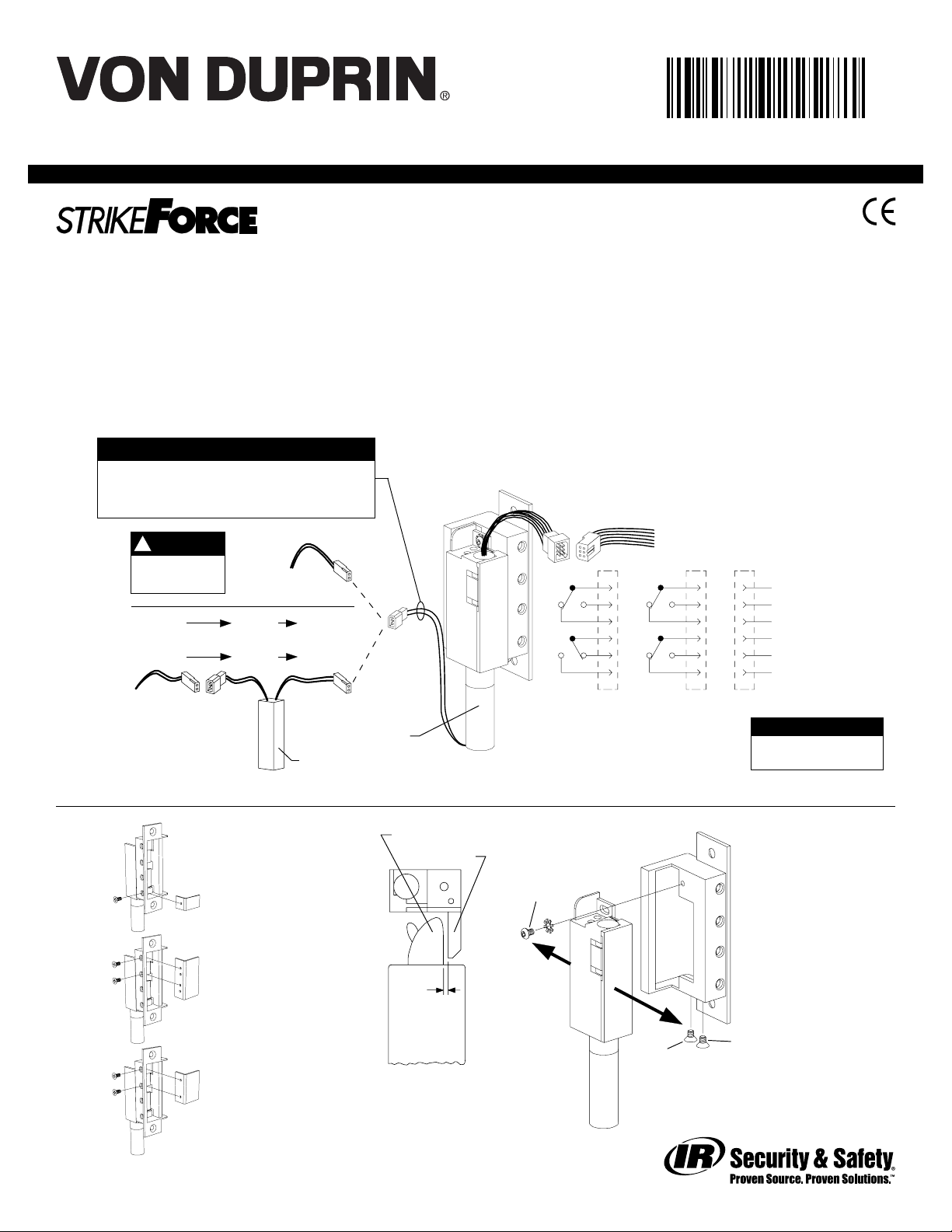
3. Wire strike (Figure 1). (Switches on 6210DS only.)
Wiring
for DC
supply
Wiring
for AC
supply
Check with factory for retrofit applications.
SOLENOID POWER REQUIREMENTS
Yellow solenoid wires: 12 VDC, 0.57 A
Black solenoid wires: 24 VDC, 0.29 A
(also shown on strike label)
NOTE
!
DC input is
{
nonpolarized
12 VAC SO-12 12 VDC
or
24 VAC SO-24 24 VDC
12 VDC
or
24 VDC
{
Use crimp
connectors to
splice field wiring
to P1 leads
P1 J1A P1A
P1
J1
Solenoid
SO-12 or SO-24
4. Install insert for auxiliary bolt operation (Figure 2).
5. Test strike: Apply solenoid power. Fail secure (FSE) lip unlocks.
Fail safe (FS) lip locks. Figure 1 shows status of switches.
6. Install strike with two #12-24 screws. Make sure clearance
between latch bolt and strike lip is 1/32” (Figure 3). If not,
uninstall strike, adjust (Figure 4), and reinstall.
7. Test door: With strike unlocked, door opens with latch bolt
extended. When door closes, latch bolt rides over strike lip.
Figure 1
J2 P2
S1
S2
Fail safe (FS)J2Fail secure (FSE)
depressed, strike lip closed and locked
(switches and tripper on 6210DS only)
1
2
3
4
5
6
J2
Switches shown with tripper
Use crimp connectors to
splice field wiring to P2
leads; insulate unused leads
S1
S2
1
2
3
4
5
6
Red (C)
Blue
Yellow
White (C)
Gray
Violet
P2
SWITCH RATINGS
Standard: 5 A, 30 VDC
Gold: 0.25 A, 30 VDC
(monitors
}
tripper)
(monitors
}
strike lip)
S1
S2
Latch bolt
Insert and location
for Von Duprin
mortise locks
Insert and location
for Schlage
mortise locks
Insert and location
for Yale, Best, and
Sargent mortise
locks
Figure 2
931001_00(7) Copyright © 2004 Ingersoll-Rand. All rights reserved.
Strike lip
1/32”
Top view;
faceplate not
shown for clarity
Figure 3
A
Figure 4
B
To adjust strike, loosen screws
A, B, and C and move backbox
sideways as necessary
C
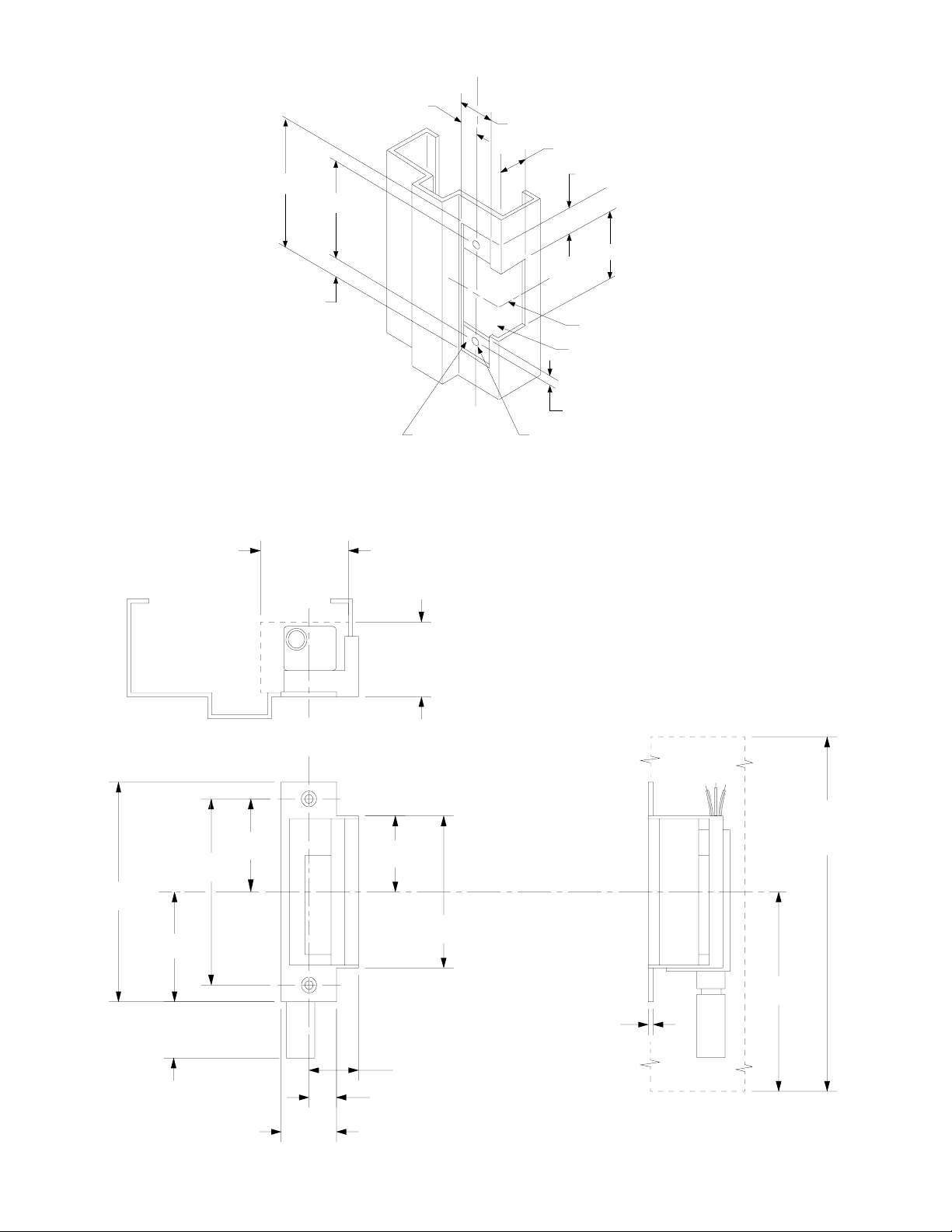
4-7/8”
4-1/8”
3/8”
LHR shown
RHR opposite
C lock and strike
L
5/8”
1-1/4”
1-9/16”
Suggested cutout
1/4” maximum
Reinforce for
strike attachment
as required
#16 drill and
#12-24 tap
2 places
Frame Preparation for Strike
3/4”
3-3/8”
C strike
L
4-7/8”
backbox
assembly
2-7/16”
Strike
4-1/8”
2-1/16”
2”minimum
clearance
C lock and strike
L
1-3/4”
minimum
clearance
1-11/16”
3-3/8”
C strike
L
12” minimum
clearance
6”
931001_00(7)
1-1/4”
1/8”
1-1/8”
5/8”
1-1/4”
Strike Dimensions and Required Clearances
 Loading...