

Von Duprin RX-LC, S1, RX Installation Instructions Manual
*941038-00*
941038-00
Switch Retrot Kit
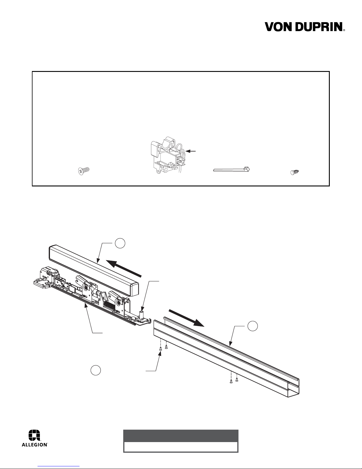
This kit includes the following parts:
RX
{
RX/RX-LC/S1
Installation Instructions
This switch is intended for signaling purposes only and is rated for a
maximum 2 ampere resistive load at 24VDC/AC. Use with inductive
or capacitive loads (magnetic locks or solenoid devices) derates the
capacity of the switch. Consult the factory for assistance.
RX-LC
8-18 X 3/8" Flat Head Screw (2)
This switch is intended for systems using low current signals. The switch is
{
rated for a maximum of 50mA. Consult the factory for assistance.
Standard (RX)
or low current (RX-LC)
Switch Assembly
Cable Tie 1.5"
Step 1 Disassemble the device. (Remove from door if mounted.)
22 Device
Remove push bar.
3
Slide
to
remove
Dogging assembly may not
be present on all devices.
Slide
to
remove
Nylon Fastener
Base Plate
Assembly
Remove screws.
1
Customer Service
1-877-671-7011 www.allegion.com/us
Remove mechanism case.
2
© Allegion 2014
Printed in U.S.A.
941038-00 Rev. 01/14-c
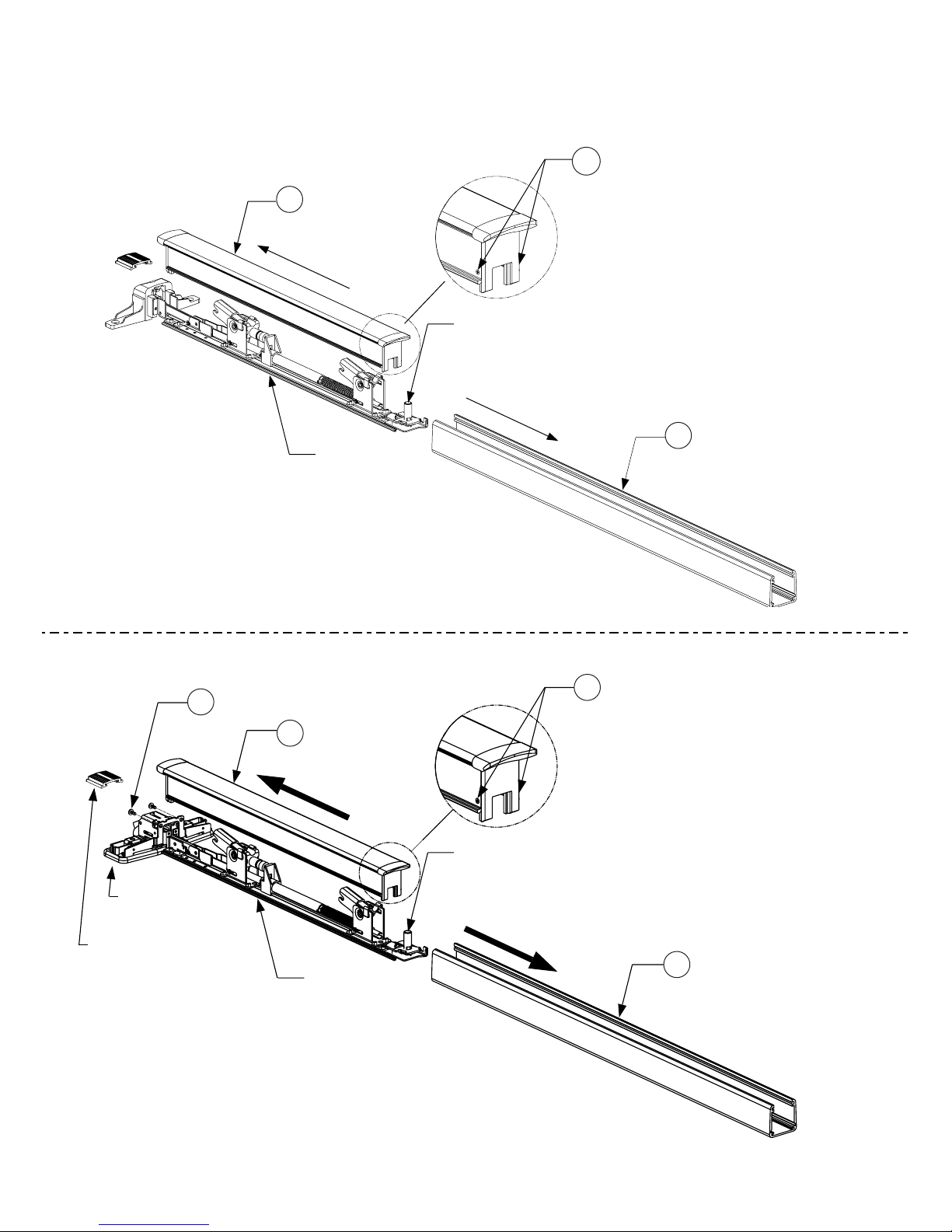
Step 1 Continued
33/35 Device
2
Remove push bar.
ø
Slide
to
remove
Base Plate
Assembly
3
If the push bar has 2 screws
ù
for end cap, replace with the
2 screws provided in this kit.
Dogging assembly may not
be present on all devices.
Slide
to
remove
1
÷
Remove mechanism case.
33A/35A & 98/99 Device
1
÷
Remove.
98/99 device
center case shown
Used on 33A/35A
device only
3
ù
Remove push bar.
Slide
to
remove
Base Plate
Assembly
If the push bar has 2 screws
4
ú
for end cap, replace with the
2 screws provided in this kit.
This end only
Dogging assembly may not
be present on all devices.
Slide
to
remove
2
ø
Remove mechanism case.
 Loading...