

Von Duprin Quiet One 9847WDC-F, Quiet One 9947WDC, Quiet One CD9847WDC, Quiet One EL9847WDC, Quiet One 9947WDC-F Installation Instructions Manual
...
VON DUPRIN
®
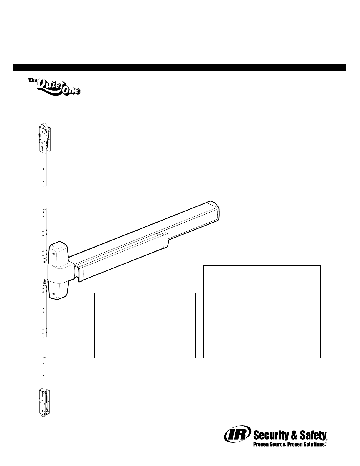
Installation Instructions
®
98/9947WDC Concealed V ertical Rod Exit Device
Wood Door Applications
Devices covered by these instructions:
98/9947WDC Concealed Vertical Rod Device
98/9947WDC-F (Fire) Concealed Vertical Rod Device
CD98/9947WDC (Cylinder Dogging) Concealed Vertical Rod Device
EL98/9947WDC (Electric Latch Retraction) Concealed Vertical Rod Device
Index:
• Screw chart ............................2
• Device installation................3-5
Special tools needed:
5/64” hex wrench
#10-24 tap
Drill bits: #25, 1/8”, 1/4”,
5/16”, 13/32”
Please give these instructions to building owner after device is installed
This product is covered by the
following patent numbers:
3,767,238 4,427,223
3,854,763 4,466,643
4,167,280 4,741,563
• Door preparation chart............ 6
• Door routing instructions .........7
• Frame preparation chart .........8
• Adjust rods ............................. 9
• Optional equipment.......... 10-11
• Cut device ............................12
FAX version 911377_00(3) Page 1 of 12
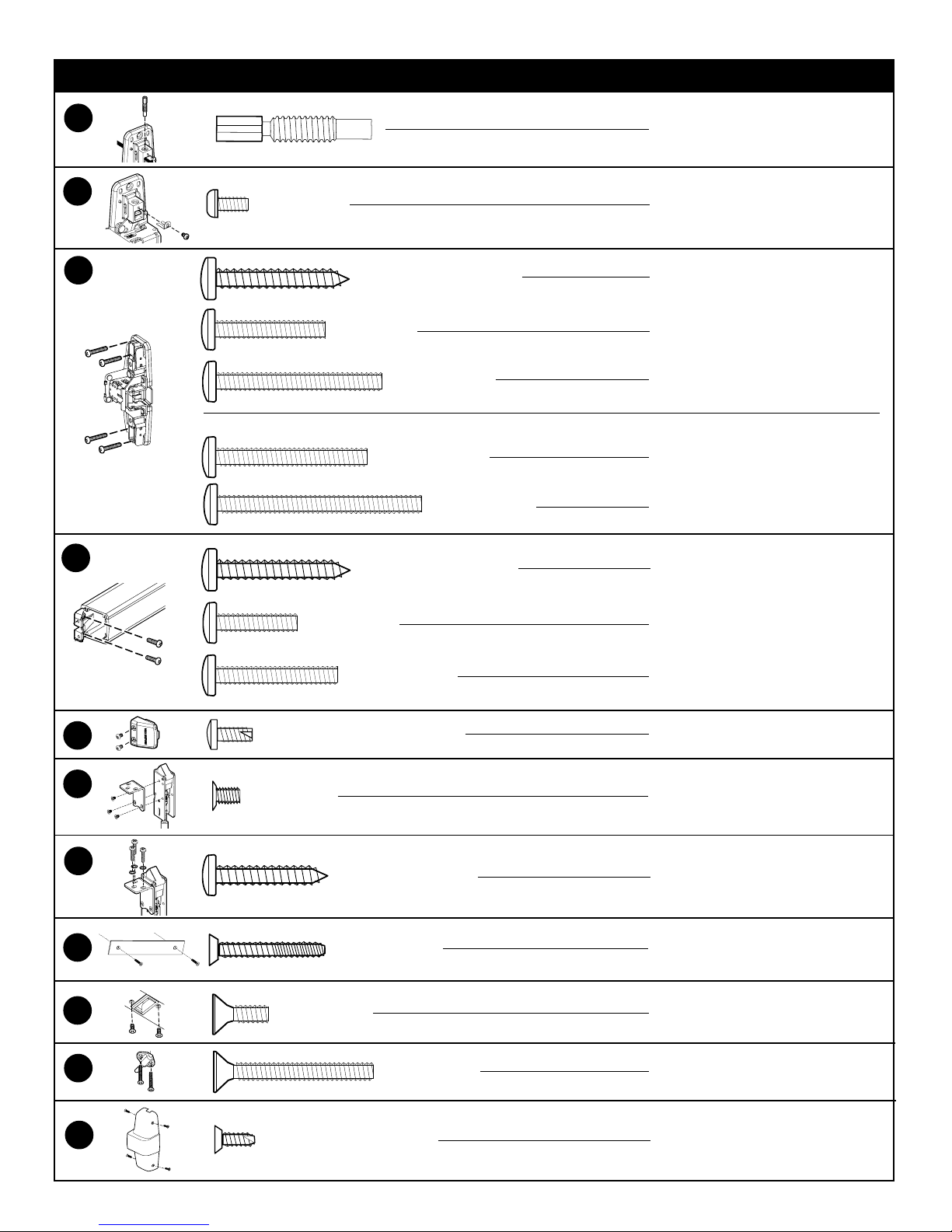
SCREW CHART
A
B
C
D
#8-32 X 5/16”
- Packaged with trim -
#10 X 1-1/4” Wood screw
#10-24 X 1”
#10-24 X 1-1/2”
#10-24 X 1-3/8”
#10-24 X 1-7/8”
#10 X 1-1/4” Wood screw
Rod adjustment screw
Rod locking screw
Surface mount (WDC)
Sexbolts (1-3/4” door)
Sexbolts (2-1/4” door)
990 trims (1-3/4” door)
990 trims (2-1/4” door)
Surface mount (WDC)
E
G
H
J
#10-24 X 3/4”
#10-24 X 1-1/8”
#10-16 X 3/8” Thread cutting
F
I
#10-32 X 1/4”
#10 X 1” Wood screw
#8-16 X 8-32 X 1”
#10-24 X 1/2”
#10-24 X 1-1/2”
Sex bolts (1-3/4” door)
Sex bolts 2-1/4” door
End cap screw
Bracket screw
Bracket to door screw
Cover plate screw
338 strike screw
Ratchet release screw
K
#8-18 X 3/8” Thread cutting
Center case cover screw
FAX version 911377_00(3) Page 2 of 12
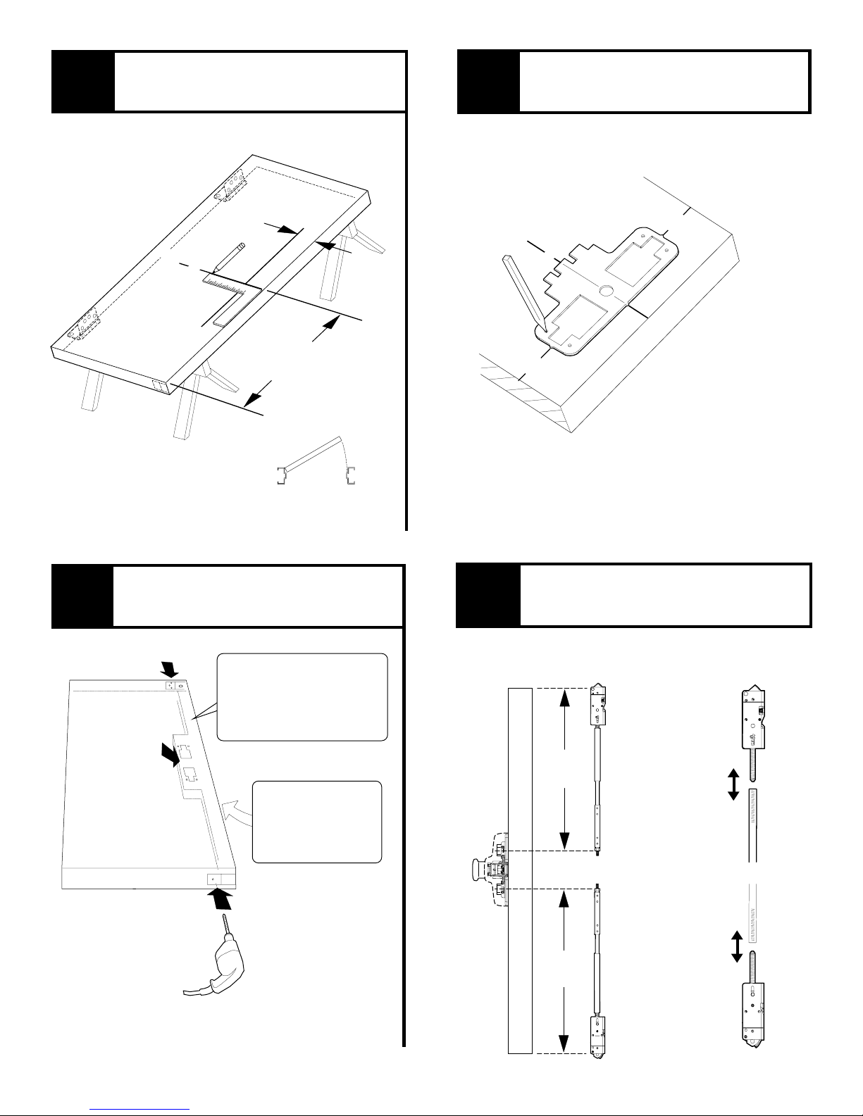
1
Draw horizontal and vertical
device center lines (C ).
L
2
Align template along center lines
and mark holes and cut-outs.
3
2-1/2”
backset
C
L
C
L
Prepare door per preparation
chart on page 6.
to bottom of
C
L
39 -9/16”
door
RHR shown
(LHR opposite)
4
C
L
C
L
C
L
Assemble rods and latches and
5
adjust length for proper door height.
If door does not have
cut-out for rods inside
lock stile, door must be
routed (see “Door Routing
Instructions” on page 7)
See trim instructions
for pull side door
preparation. Line X-X
in trim instructions is
same as device C.
L
Follow red and blue instruction cards on
rods to set initial rod length
Top
length
Bottom
length
Fine tune the
overall length
by threading
latch in or out
of rod
FAX version 911377_00(3) Page 3 of 12
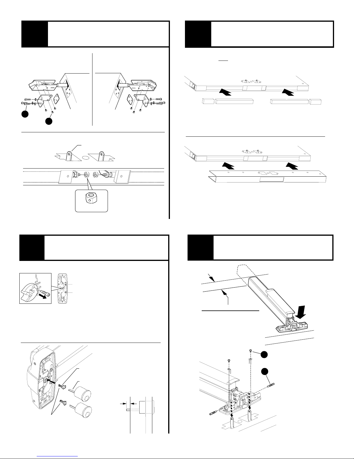
5
Secure latches and rods into door
5
as shown and attach offset links.
6
Install blocking and door wrap
(if using door wrap).
G
Top latch
& rod
F
Offset link
Lock nut
Bottom latch
& rod
NOTE: If not using door wrap, the blocking can be
installed after device is installed.
Blocking
See page page 7 for blocking dimensions
Door wrap
Optional- to be used on fire doors only,
not supplied by Von Duprin
Blocking
If using an outside cylinder, check NL
7
NL drive screw
Note: When the NL
drive screw is left in
back of device, the
outside cylinder
will function only
as a Night Latch.
drive screw and install tailpiece guide.
5
When installing trim that has a
functional lever, knob, or thumb
piece AND an outside cylinder to
lock and unlock the trim, remove NL
drive screw from back of device.
DO NOT remove NL drive screw for
the following trims:
NL, EO, DT, TP-2, L-2, and K-2.
With “BE” trim, device may need
rehanded. Look for instructions on
back of trim.
Tailpiece guide
Tailpiece
Cut tailpiece
if needed
1/2”
Check device length and attach
8
device center case to two offset
links as shown.
2” Minimum clearance
(with endcap removed)
If device is too long for
door, see “Cut Device”
on back cover
Center case
(align with
mounting holes)
B
A
Rotate tailpiece
guide to match
tailpiece
Door
surface
FAX version 911377_00(3) Page 4 of 12
 Loading...