

Von Duprin QEL94/9547 Series, QEL94/9547, QEL94/9548, QEL94/9547-LBR Installation Instructions Manual
*24158859*
24158859
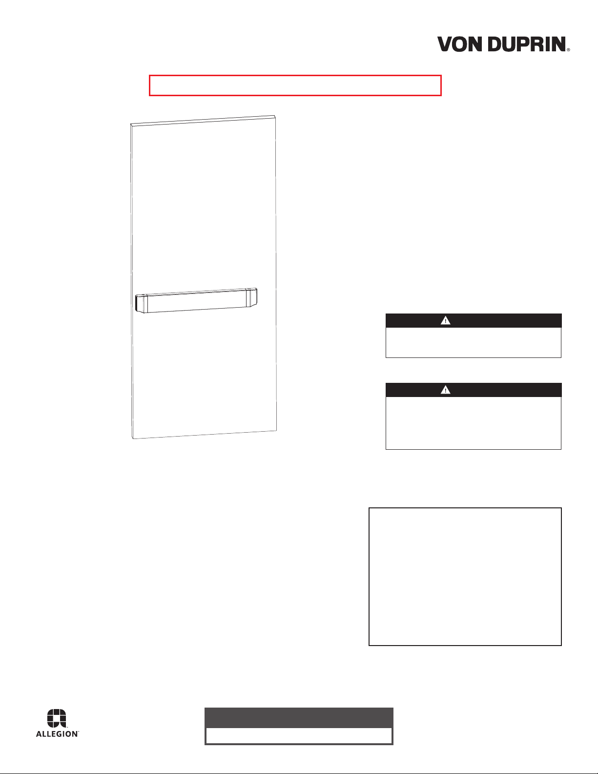
Recessed Exit Device
QEL94/9547
FOR DEVICES SOLD PRIOR TO DEC. 2014
Install in accordance with instructions or
Installation Instructions
WARNING
device will not function.
Devices covered by these instructions:
QEL94/9547/48 Concealed Vertical Rod Device (Panic and Fire)
QEL94/9547-LBR Concealed Vertical Rod Device (Fire)
Read All Warnings
Before Starting Installation!
CAUTION
For less bottom rod (LBR) devices, do not
cover the door gap at the auxiliary fire latch
with a door edge guard or similar product.
If edge guard is installed, remove it.
Index
• Warnings .......................... .......... 1
• Parts ........................................... 2
• General Information .................... 3
• Specifications ............................. 3
• Tools Needed ............................. 3
• Set Handing ............................... 3
• Installation .................................. 4
Customer Service
1-877-671-7011 www.allegion.com/us
© Allegion 2018
Printed in U.S.A.
24158859 Rev. 10/18-c
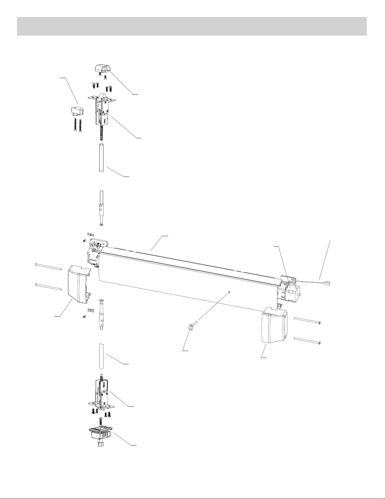
PARTS
Ratchet
release
assembly
Soffit strike
Top latch
assembly
Top rod
assembly
End cap
Bottom rod
assembly
Bottom latch
assembly
Device
(panic devices
QEL cable
QEL motor
Dogging key
End cap
only)
2 of 16
Sill strike
GENERAL INFORMATION
y embedding
The QEL94/9547 Exit Device is designed to provide reduced pushpad projection and a unique appearance b
the device into the face of the door.
These instructions assume that a factory-prepared door and frame are being used.
Before starting installation, review "Warnings," "Parts," "Specifications," and "Tools Needed."
SPECIFICATIONS
Mechanical
• Vertical rods adjustable for doors 6'8" to 8' tall
• Rods for 10' doors are available upon request
• Pushpad projection (depressed) 1¹⁄₈" to 1¹⁄₄"
Electrical Load
• Voltage: 1.4 A inrush (0.5 sec)
• Current: 0.14 A holding
2.0 A calibrate (3 sec, one time)
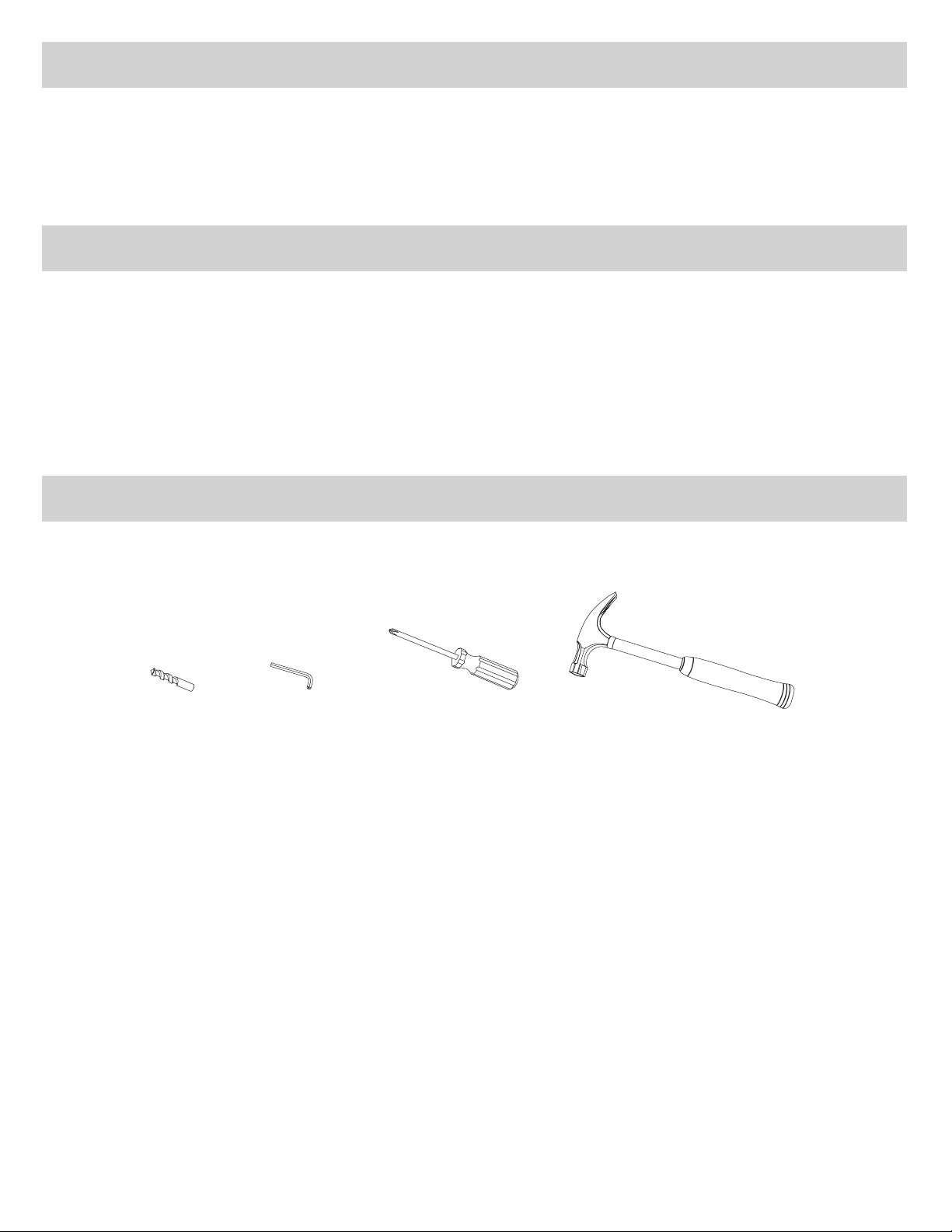
TOOLS NEEDED
These are the tools needed for installing a QEL94/9547 into a factory-prepared door and frame.
¹⁄₂" drill bit ⁷⁄₆₄" hex key Phillips screwdriver Hammer
3 of 16
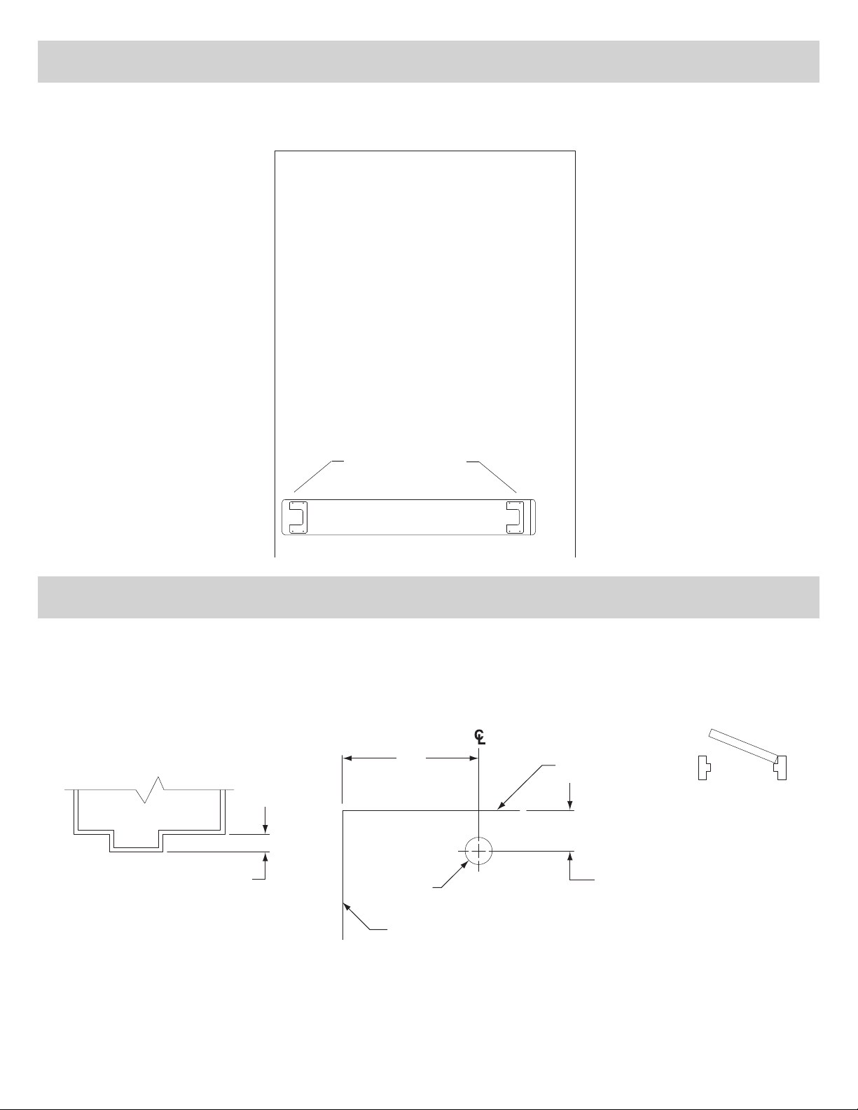
1 PREPARE DOOR FOR TRIM (SKIP THIS STEP IF NOT USING TRIM)
Drill through the four mounting holes and trim access hole at the latch side of the cutout. See trim installation
instructions for hole sizes and locations.
Latch
side
Hinge
side
2 PREPARE HOLE FOR RATCHET RELEASE PLUNGER
a. Determine stop height (Figure 2-1), then mark center of hole on device side of door (Figure 2-2).
b. Drill a ¹⁄₂” diameter hole where marked through device side of door only.
Latch
2³⁄₄"
Top of door
LHR shown
RHR opposite
4 of 16
Stop height
¹⁄₂" dia.
Side opposite hinges
¹¹⁄₁₆" for ¹⁄₂" stop height
¹³⁄₁₆" for ⁵⁄₈" stop height
¹⁵⁄₁₆" for ³⁄₄" stop height
Figure 2-1 Figure 2-2
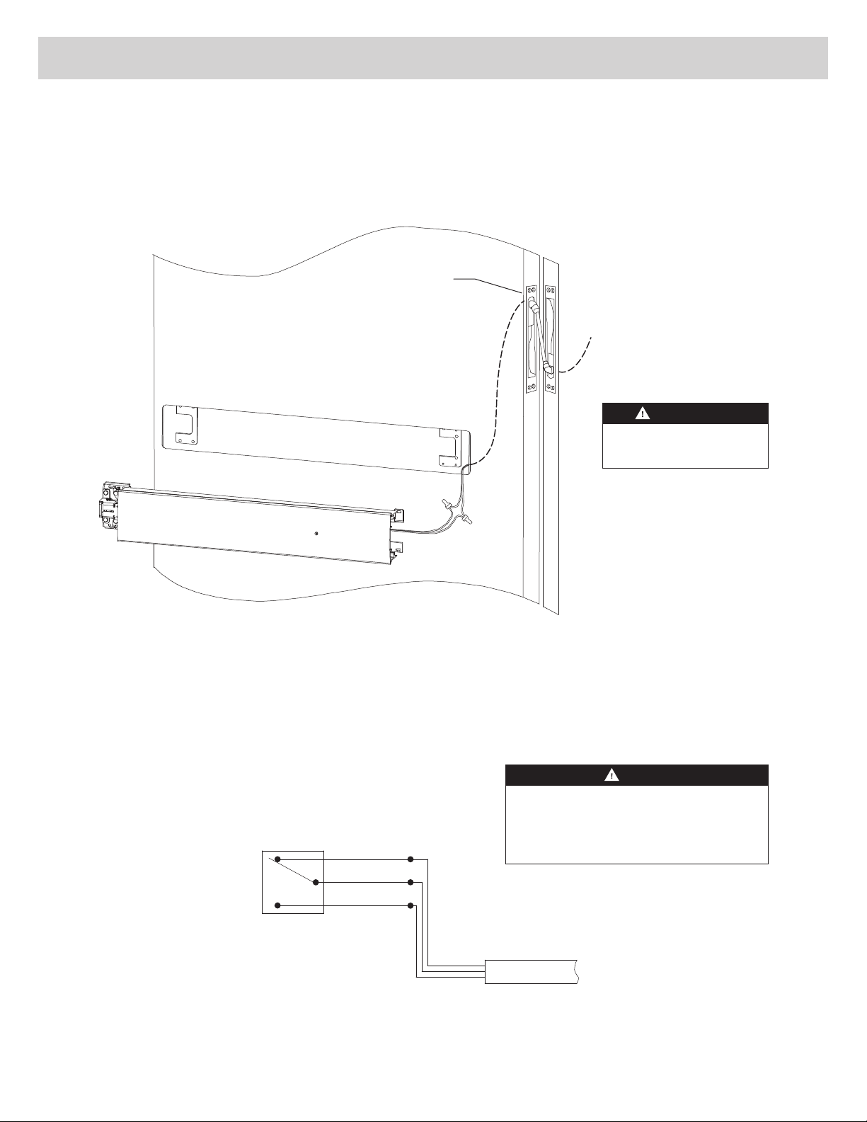
3 WIRE LX SWITCH (LX DEVICES ONLY)
a. Connect field wiring to frame side of power transfer (Figure 3-1).
b. See LX switch wiring information (Figure 3-2) for switch configuration.
c. Connect LX switch wiring to door side of power transfer using crimp connectors. Unused wires should be insulated
separately.
Power transfer
(Von Duprin EPT10 shown, or
EPT2 can be used on QEL
device without LX switch)
Field
wiring
WARNING
Disconnect power before
wiring LX switch.
NC
NO
Figure 3-1
Switch
Figure 3-2
Yellow
Red
Blue
NOTE
The latch bolt monitor switch is activated
whenever the latch bolt is retracted. The
switch function is shown with the latchbolt
extended and the touchbar not depressed.
5 of 16
 Loading...