

Von Duprin LGO Installation Instructions Manual
*941277-00*
941277-00
Latch Guard
LGO
Installation Instructions
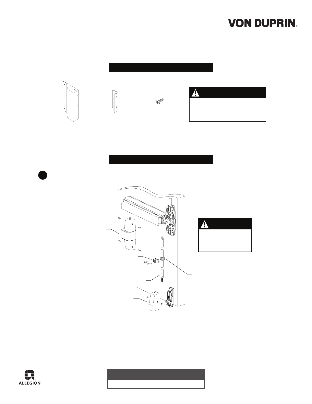
PARTS
NOTE
This latch guard will cover a
bottom latch that projects as
far as 1-13/16” from the door.
Latch Guard Latch Guard
Remove center case cover, latch cover, rod guide, and bottom rod (Figure 1).1
Center case
cover
Bracket
Rod guide
Bottom rod
#8-32 Screw
(quantity 7)
INSTALLATION
NOTE
Rod for 33/35 and
88 device unscrews
at device.
Rod guide
bushing
Latch cover
Figure 1
Customer Service
1-877-671-7011 www.allegion.com/us
© Allegion 2014
Printed in U.S.A.
941277-00 Rev. 06/14-b
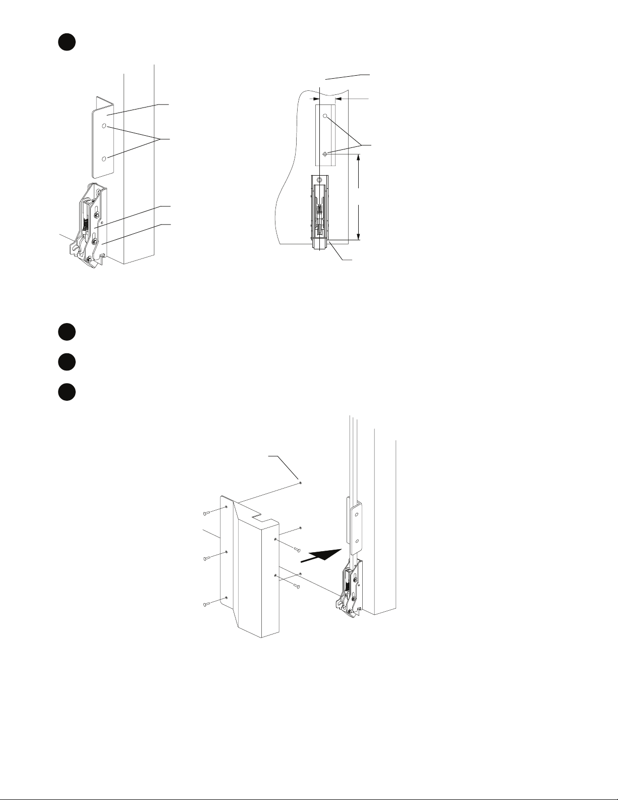
2 Locate and install latch guard bracket with two #8-32 screws (Figure 2 and Figure 3).
Measure from center line of latch
13/16” for Von Duprin 22, 33/35,
33A/35A, and 98/99 devices
15/16” for Von Duprin 88 devices
Use latch guard bracket as a
template for locating holes; drill
and tap door for #8-32 screws
5”
Measure from bottom of latch case
Latch guard
bracket
Tapped
holes
Latch case
Latch
mounting
bracket
C
L
Figure 3 Figure 2
3 Reinstall rod and adjust rods per device instructions.
4 Reinstall rod guide bushing, rod guide, center case cover, and latch cover.
5 Drill and tap door for #8-32 screws and install latch guard with five #8-32 screws (Figure 4).
Drill and tap three
#8-32 mounting
holes in door
Figure 4
 Loading...