

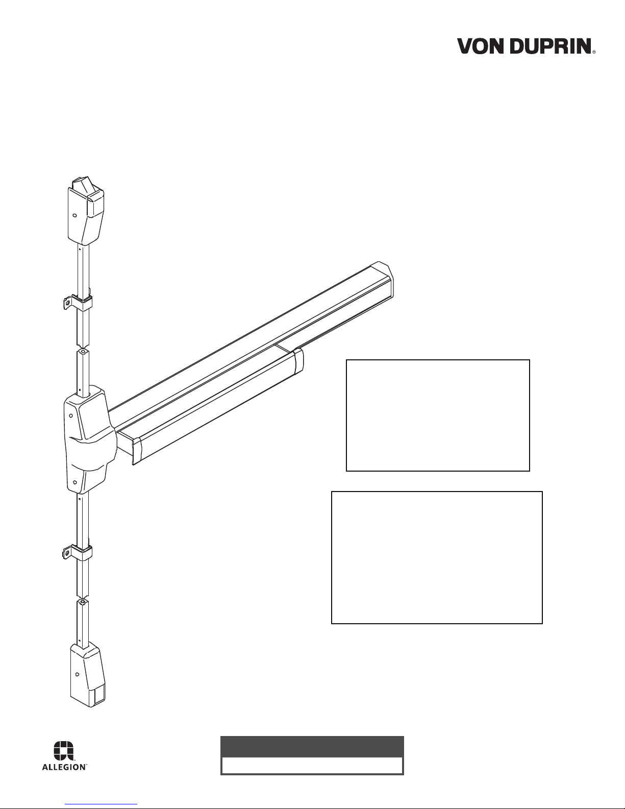
Von Duprin 98/9927, CD98/9927, EL98/9927, 98/9927-F Installation Instructions Manual
*911375-00*
911375-00
Surface Vertical Rod Exit Device
EL98/9927 (Electric Latch Retraction) Surface Vertical Rod Exit Device
98/9927
Installation Instructions
Devices covered by these instructions:
98/9927 Surface Vertical Rod Exit Device
98/9927-F (Fire) Surface Vertical Rod Exit Device
CD98/9927 (Cylinder Dogging) Surface Vertical Rod Exit Device
Special tools needed:
5/64” hex wrench
#10-24 tap
Drill bits: #25, 1/8”, 1/4”,
5/16”, 13/32”
Index:
• Screw chart ............................. 2
• Preparation chart .................... 3
• Device installation ............... 4-6
• Cut top rod ............................. 7
• Install rod extension ................ 7
• Optional equipment ............... 8
• Cut device .............................. 8
Customer Service
1-877-671-7011 www.allegion.com/us
© Allegion 2016
Printed in U.S.A.
911375-00 Rev. 12/16-e
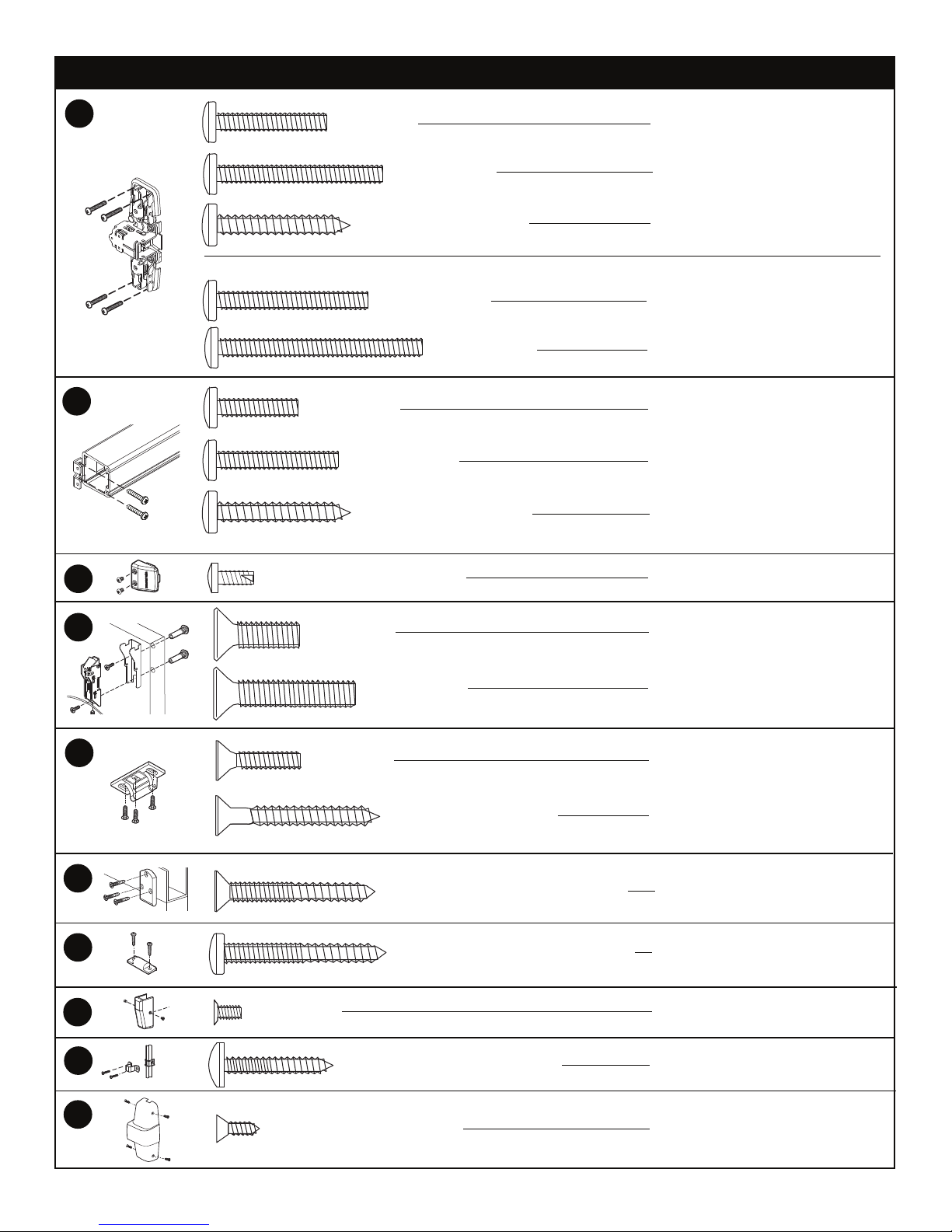
SCREW CHART
A
B
- Packaged with trim -
#10-24 X 3/4”
#10-24 X 1”
#10-24 X 1-1/2”
#10 x 1-1/4” Wood screw
#10-24 X 1-3/8”
#10-24 X 1-7/8”
#10-24 X 1-1/8”
#10 x 1-1/4” Wood screw
Surface mount or
Sex bolts (1-3/4” door)
Sex bolts (2-1/4” door)
Surface mount (wood)
990 trims (1-3/4” door)
990 trims (2-1/4” door)
Surface mount or
Sex bolts (1-3/4” door)
Sex bolts 2-1/4” door
Surface mount (wood)
C
D
E
F
G
H
#10-16 x 3/8” Thread cutting
1/4-20 X 3/4”
1/4-20 X 1-1/4”
#10-24 X 3/4”
#10 x 1-1/2” Wood screw
#10-12 x 10-24 x 1-1/4” Combination
#10-12 x 10-24 x 1-1/4” Combination
#8-32 X 1/4”
End cap
1-3/4” door
2-1/4” door
Metal frame
Wood frame
Metal or wood frame
Variable floor surfaces
Latch covers
I
J
2
#8-18 x 3/8” Thread cutting
#10-12 x 10-24 x 1” Combination
Metal or wood door
Center case cover
PREPARATION CHART
Go to instructions on next page before using Preparation Chart
Top strike
#25 Drill
#10-24 Tap
Latches
5/16” Drill (device side)
13/32” Drill (trim side)
Metal
MetalWood
1/8” Drill
pilot 1” deep
13/32” Drill thru
Wood
C
L
*End cap bracket - 2 holes
Surface mount Sex bolts
#25 Drill
Metal
#10-24 tap
1/8” Drill
pilot 1” deep
Wood
*Prepare holes after lock side of device
is mounted and hinge side is leveled
1/4” Drill (device side)
Metal
13/32” Drill (trim side)
13/32”
Wood
Drill thru
C
X
X
*Rod guides
#25 Drill
#10-24 Tap
MetalWood
1/8” Drill
pilot 1” deep
*Use rod guide
as a template
to mark holes
Center case - 4 holes
Surface mount Sex bolts or 990 trims
#25 Drill
Metal
#10-24 tap
L
1/8” Drill
pilot 1” deep
Wood
1/4” Drill (device side)
Metal
13/32” Drill (trim side)
13/32”
Wood
Drill thru
Door cut-outs
Outside cylinder applications:
Mark with template and cut-out:
Metal door (cut device side)
Wood door (cut thru)
For trim applications with working
lever, thumbpiece, or knob:
Mark with template and cut out:
(cut device side only)
If door already has this cut-out for
trim, no further cutting is necessary
See template
for strike
variations
Bottom strike
#25 Drill
#10-24 Tap
MetalWood
1/8” Drill
pilot 1” deep
3
 Loading...