

Von Duprin Chexit CX33A/35A, Chexit CX98/99 Installation Instructions Manual
M
T
VON DUPRIN
®
Installation Instructions – Electrical
S
I
F
S
I
E
HE
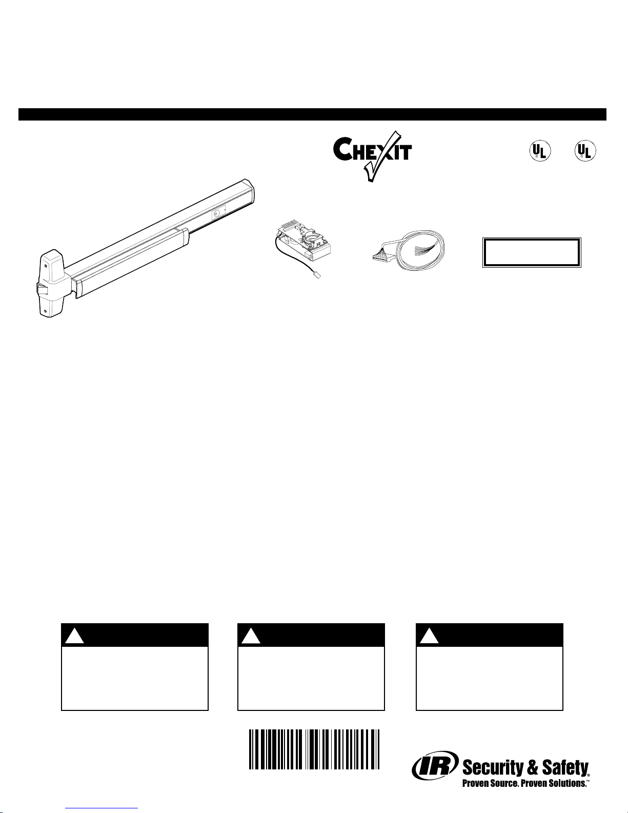
CX33A/35A &CX98/99 Device
CX Rim Exit Device
Chexit Module
T
®
Cable
PUSH UNTIL ALARM SOUNDS
DOOR CAN BE OPENED
A
D
L
C
IN 15 SECONDS
Door Sign
(CX98/99 shown)
GENERAL INFORMATION
The Von Duprin Chexit device is designed for accident hazard or fire exit applications. It meets both life
safety and security needs as well as all requirements of NFPA101 for “Special Locking Arrangement” and
UBC “Special Egress-Control Devices.”
The Von Duprin Chexit device sounds an alarm and keeps an exit door secured for 15 seconds following an
attempt to exit. The Chexit releases immediately upon a fire alarm condition.
®
S
I
F
S
I
E
A
D
L
C
C
ELECTRICAL SPECIFICATIONS
Voltage...............................................................24 VDC
Current...............................................................0.4 A
Current on arming...........................................300-mS 16-A in-rush
External alarm dry contacts (NO and C)....24 VDC, 1 A rating
Normally closed inputs ..................................Fire alarm (FA; required)
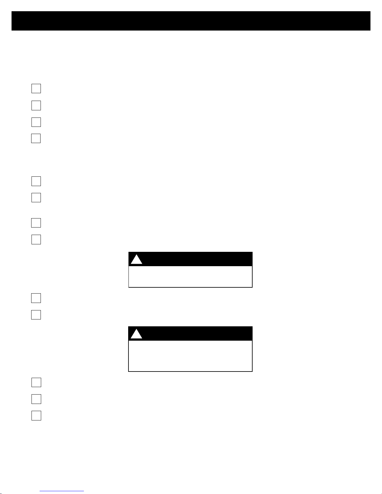
WARNING
!
Do not exceed rated
specifications.
911352_00(5) Page 1 of 8
External inhibit (EI)
Door position switch (DPS)
WARNING
!
The Chexit device must be
installed in accordance
with these instructions by
a qualified electrician.
911352-00
WARNING
!
Wiring must be in
accordance with all local
codes and regulations.
PRE-INSTALLATION CHECKLIST
Complete the items on the checklist below before installing the Chexit module. Each component listed
should be prepared and installed according to the installation instructions supplied with it.
Mechanical Preparation
1. Door and frame have been prepared for power transfer.
2. Chexit device has been installed. (See instructions packaged with Chexit device.)
3. Trim such as a lever handle, if used, has been installed.
4. Suggested: Obtain a 1 1/4” or 1 3/8” mortise cylinder. (It is easier to install the mortise cylinder
during electrical installation than after electrical installation.)
Electrical Preparation
1. Read all of these instructions before installing the Chexit module.
2. If available, get a wiring diagram for your installation. Otherwise, refer to Figures 2 and 3 and
Table 1 in “Typical Wiring”and mark the components you use in Table 1.
3. Determine the physical location of each component used (see Figure 1).
4. Pull field wiring between component locations and frame side of power transfer (see Figure 1).
!
The wiring requirements in Table 2 in
“Typical Wiring” must be followed.
5. Mount components and connect them to field wiring (see Figure 2 or Figure 3).
6. Connect field wiring to frame side of power transfer. (Route wires through frame back box.)
!
Components must be connected to
wire colors as shown in Figures 2
7. Install frame back box and frame side of power transfer.
8. Get requirements for Chexit option switches, record in Table 3 in “Options,” and set switches.
IMPORTANT
IMPORTANT
and 3 in “Typical Wiring.”
9. Complete steps 1 through 10 of “Installation.”
To install mortise cylinder after electrical installation:
1. Remove end cap and end cap bracket (see “Installation” step No. 1).
2. Slide cover plate out until knurled ring is visible; install cylinder (see “Installation” step No. 5).
3. Complete steps Nos. 5, 7, 8, and 10 of “Installation.”
911352_00(5) Page 2 of 8
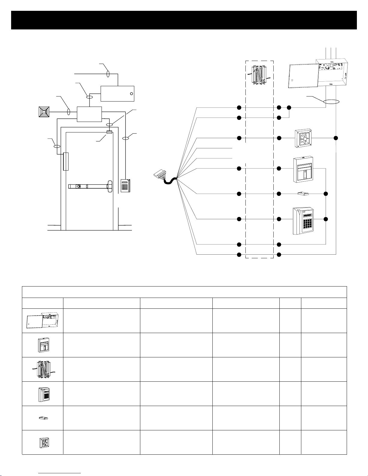
TYPICAL WIRING
2 x 18 GA
External
alarm
8 x 18 GA
plus 2 x *
* See “Power
*
Supply Output”
in Table 2 for
wire GA
*
EPT
3 x 14 GA
2 x *
*
Junction
box
DPS
Chexit
Power
supply
External
inhibit
Single Door Application
Red (+24)
2 x 18 GA
2 x 18 GA
(plus power if
required)
Cable to
Chexit
device
Blue (C)
Brown (NO)
Violet (CM-)
Gray (CM+)
Yellow (FA)
Orange (DPS)
Green (EI)
Not used;
}
separately
Power
transfer
insulate
Power supply
input
Power supply
output
+
FIRE
+24
_
GND
Figure 1. Component Placement and
Wiring Requirements, Single Door
ComponentPicture
24 VDC power supply
FIRE
Building fire alarm
(normally closed contacts)
Power transfer
(EPT-10 shown)
External inhibit device
(card reader, key switch, etc.;
normally closed contacts)
Door position switch
(normally closed contacts)
External alarm
White (SC)
Black (GND)
Figure 2. Wiring Connections, Single Door
Table 1. Installation Components
Function
Supplies power to Chexit
Unlocks Chexit in case
of fire alarm
Transfers electrical power
through frame to door
(wires concealed)
Allows authorized egress
or ingress without alarm
Arms Chexit 2.5 seconds
after door closes; sounds
alarm if door forced open
Provides louder alarm than
Chexit internal horn
Optional/Required If Not Used...
Required
(Von Duprin PS873)
Required
Highly
recommended
Optional (wire multiple
external inhibit devices
in series)
Optional
Optional
Used?
Yes
Yes
Required
Required
Use door loop or
electric hinge
Connect green
wire to
white wire
Connect orange
wire to white
wire
Insulate blue and
brown wires
separately
911352_00(5) Page 3 of 8
 Loading...