

Von Duprin DE5300, Chexit, RCM Special Instructions Manual
*941316-00*
941316-00
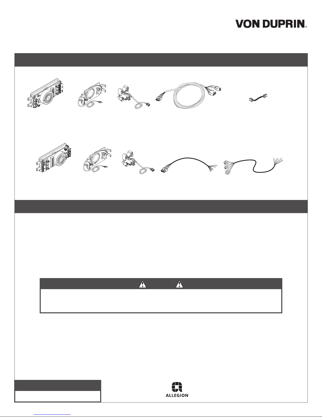
Service Parts Replacement
Chexit Service Parts
Chexit/RCM/DE5300
Special Instructions
Chexit/RCM/DE5300 Service Parts
Chexit
Module
DE5300/RCM Service Parts
DE5300/RCM
Module
Key Switch
RX Switch
Chexit
Field Wiring Cable
Key Switch
RX Switch
DE5300/RCM
Field Wiring Cable
Table of Contents
Module Replacement on CX Device........................................ 2-3
Module Replacement on DE5300 or RCM Device .................. 4-5
Key Switch Replacement CX Device....................................... 6
Key Switch Replacement DE5300 or RCM Device ................. 7
RX Switch Replacement on Chexit or RCM Exit Device ......... 8
Blocking Device Cable
(connected to motor)
DE5300/RCM
Device Wiring Cable
To avoid risk of shock, disconnect AC power from power supply before proceeding with component
replacement. If using Battery Backup option, unplug all four wires from battery terminals.
Customer Service
1-877-671-7011 www.allegion.com/us
WARNING
© Allegion 2015
Printed in U.S.A.
941316-00 Rev. 07/15-a
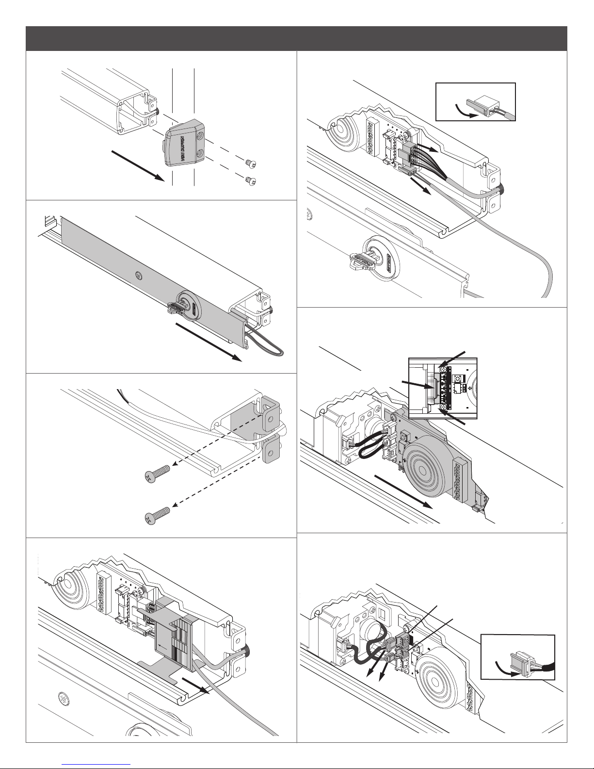
Module Replacement on a Chexit Device
BLOCKING
DEVICE
RESET
TRIM
DEVICE
REX RENBLK
STATUS
Pry here
1a Removal of Chexit Module. First, remove end cap.
1b Slide and remove Cover Plate.
1e Press release tabs on Chexit Field Wiring Cable and
Key Switch Cable to disconnect from module.
Press tab to release
connectors
1f Insert athead screwdriver between module and motor
(only in the area shown) and pry until the module
disengages.
1c Remove end cap bracket.
1d Slide Wire Guard out of end of case.
after cables are
CX Module
Install this bracket
plugged into the
WIRE COLOR CHART
RED 24V BLUE AL
www.allegion.com/us
BLACK GND BROWN AL
GREEN INH WHITE SE
ORANGE DPS VIOLET SEC
YELLOW FA TAN N/A
GREY GNG PINK N/A
DO NOT pry
in this area.
Pry here
1g Disconnect Blocking Device Cable from 3-pin
connector labeled “BLK” and RX Cable from 2-pin
connector labeled “REX” on Module. Slide Chexit
Module fully out of device case.
3-Pin
Connector
2-Pin
ACTUATOR
BLOCKING
Connector
Press tab to release
connectors
2
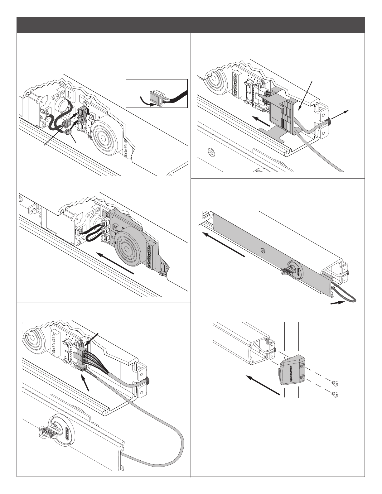
Module Replacement on a Chexit Device (Continued)
Tension
1h Installation of Chexit Module. First, slide Module
into device case. Connect Blocking Device Cable from
motor to 3-pin connector on Module. Connect 2-pin
cable from under motor to Request-to-Exit connector
labeled “REX” on Module.
If removal is needed, press
release tab on connector.
ACTUATOR
BLOCKING
2-Pin
3-Pin
Connector
Connector
1k Slide Wire Guard into case end and above Key Switch
and Chexit Door Wiring Cables until making contact
with module.
If trim is used, cover its
cable with wire guard also.
Push excess
cable into door.
after cables are
CX Module
Install this bracket
plugged into the
WIRE COLOR CHART
RED 24V BLUE AL
www.allegion.com/us
BLACK GND BROWN AL
GREEN INH WHITE SE
ORANGE DPS VIOLET SEC
YELLOW FA TAN N/A
GREY GNG PINK N/A
1i Push Module toward motor until it snaps into place.
Snap into
place
1j Connect Field Wiring Cable and Key Switch Cable to
Module as shown.
1l While keeping tension on the Key Switch Cable and
pushing wires at against door, slide Cover Plate fully
into place. After Cover Plate is installed, push Key
Switch Cable under the wire guard
1m Install end cap.
3
 Loading...