

Von Duprin 99, CD98, 98-F, 99-F, CD99 Installation Instructions Manual
...
Installation Instructions
®
98/99
CD98/CD99 (Cylinder Dogging) Rim Exit Device
98-2/99-2 (Double Cylinder) Rim Exit Device
EL98/EL99 (Electric Latch Retraction) Rim Exit Device
Series Rim Exit Device
Devices covered by these instructions:
98/99 Rim Exit Device
98/99-F (Fire) Rim Exit Device
911373-00
Please give these instructions to building owner after device is installed
Special tools needed:
5/64” hex wrench
#10-24 tap
5/8” spade drill (
Drill bits: #25, 1/8”, 1/4”,
99-F wood door
5/16”, 3/8”, 13/32”
s Screw chart ............................. 2
s Preparation chart .................... 3
s Device installation ............... 4-5
)
s Optional equipment ............ 6-7
s Cut device .............................. 8
s 499F strike installation ............ 8
© 2011 Ingersoll-Rand Company
1-877-671-7011
911373_00 Rev. 3/11_c
Index:
A
#10-24 X 3/4”
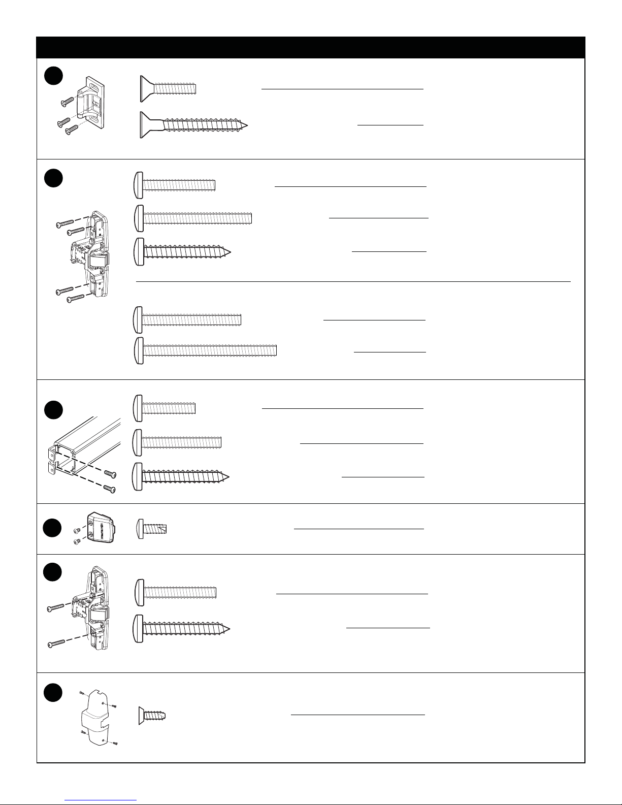
SCREW CHART
Metal frame
B
C
- Packaged with trim -
#10-24 X 3/4”
#10 X 1-1/2” Wood screw
#10-24 X 1”
#10-24 X 1-1/2”
#10 X 1-1/4” Wood screw
#10-24 X 1-3/8”
#10-24 X 1-7/8”
Wood frame
Surface mount or
Sex bolts (1-3/4” door)
Sex bolts (2-1/4” door)
Surface mount (wood)
990 Trims (1-3/4” door)
990 Trims (2-1/4” door)
Surface mount or
Sex bolts (1-3/4” door)
D
E
F
#10-24 X 1-1/8”
#10 X 1-1/4” Wood screw
#10-16 X 3/8” Thread cutting
#10-24 X 1”
#10 X 1-1/4” Wood screw
#8-18 X 3/8” Thread cutting
Sex bolts (2-1/4” door)
Surface mount (wood)
End cap screw
Surface mount (metal)
Surface mount (wood)
Cover screw
2
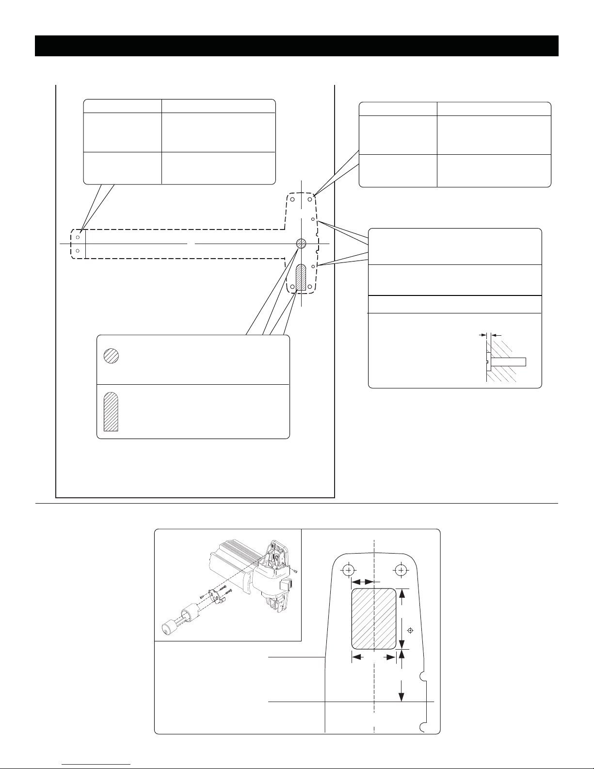
PREPARATION CHART
Go to instructions on next page before using preparation chart
*End cap bracket - 2 holes
Surface mount Sex bolts
#25 Drill
Metal
#10-24 tap
1/8” Drill
pilot 1” deep
Wood
*Prepare holes after lock side of device
is mounted and hinge side is leveled
1/4” Drill (device side)
Metal
13/32” Drill (trim side)
13/32”
C
L
Drill thru
RHR shown
(LHR opposite)
Wood
Door cut-outs
Outside cylinder applications:
Mark with template and cut-out:
Metal door (cut device side)
Wood door (cut thru)
X
C
X
Center case - 4 holes
Surface mount Sex bolts or 990 trims
#25 Drill
Metal
#10-24 tap
1/8” Drill
pilot 1” deep
Wood
L
Center case - 2 support holes
#25 Drill #10-24 tap
Metal
1/8” Drill pilot 1” deep
Wood
For 98-F/99-F (fire) wood door
#825 Sex bolts (2) required
3/8” Drill thru
5/8” Spade drill
Wood or
composite
1/16” Deep outside
1/4” Drill (device side)
Metal
13/32” Drill (trim side)
13/32”
Wood
Drill thru
1/16”
For trim applications with working
lever, thumbpiece, or knob:
Mark with template and cut out:
(cut device side only)
CUT-OUT FOR 99-2 “DOUBLE CYLINDER” OPTION
11/16”
1-3/4”
1-1/4”
1-3/8”
Device and strike
C
L
C
L
3
 Loading...