

Von Duprin 33/35A, CD33/35A, 33/35A-F, SS33/35A, EL33/35A Installation Instructions Manual
*911402-00*
911402-00
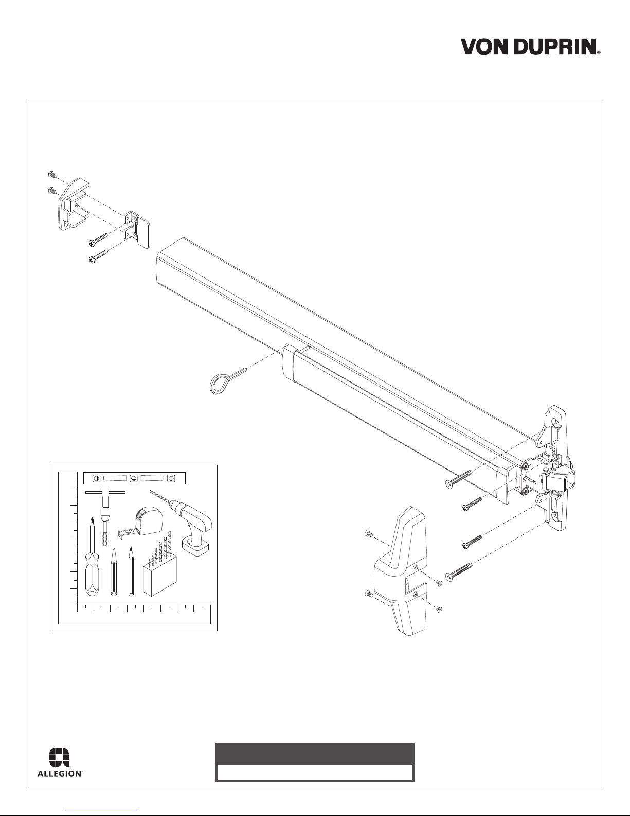
Rim Exit Device Installation Instructions
33/35A Series
Devices covered by these instructions:
33/35A Rim Exit Device
33/35A-F Rim Exit Device
CD33/35A Rim Exit Device
EL33/35A Rim Exit Device
SS33/35A Rim Exit Device
(use with non-fire devices to lock down pushbar)
#10-24
Dogging Key
Customer Service
1-877-671-7011 www.allegion.com/us
© Allegion 2016
Printed in U.S.A.
911402-00 Rev. 05/16-d
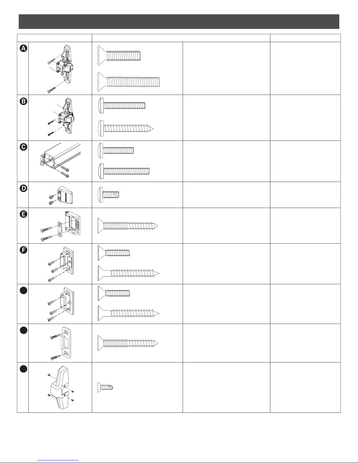
SCREW CHART
G
H
I
Device Subassembly
Screw Application
Z\v-20 x1” (25 mm)
Z\v-20 x 1-Z\x” (38 mm) 2Z\v” (57 mm) door
#10-24 x 1” (25 mm)
#10 x 1Z\v” (32 mm) Wood screw
#10-24 x C\v” (19 mm)
#10-24 x 1Z\,” (29 mm) Sex bolts, 2Z\v” (57 mm) door
#10-16 x C\,” (10 mm) Thread cutting
Trim mount or sex bolts:
1C\v” (44 mm) door
Metal door surface mount
(Yellow)
Wood door surface mount
Surface mount or Sex bolts
1C\v” (44 mm) door
End cap
#10-12 x 10-24 x 1Z\v” (32 mm)
combination
#10-24 x C\v” (19 mm)
#10 x 1Z\x” (38 mm) Wood screw
#10-24 x C\v” (19 mm)
#10 x 1Z\x” (38 mm) Wood screw
#10-12 x 10-24 x 1Z\v” (32 mm)
combination
#8-18 x C\,” (10 mm) Thread cutting
Metal or wood frame
Metal frame
Wood frame
Metal frame
Wood frame
Metal or wood frame
Center case cover
2
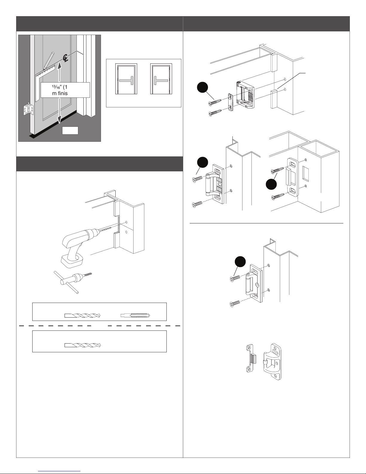
1 Draw horizontal device and strike center lines (
Panic Device
* 39ZC\zn” (101.1 cm)
from finished floor
RHR LHR
For double doors with a
*
mullion and strike already
RHR
installed, use existing
strike center line.
C
).
L
3 Install strike using two screws only at this time.
Door
Install strike
1/16” past door
E
1439 Strike (standard)
side of stop
2 Prepare frame for strike using paper templates.
See pages 8 through 12 for strike templates and frame
preparation dimensions.
Metal
Wood
1439 strike
preparation
shown
#25
OR
Z\,” (3 mm) x 1” (25 mm) deep
#10-24
F
Door
H
299 Strike
Fire Rated Device
G
299F Strike
For 499F strike installation, see page 6.
Mullion
1606 Strike
See “Screw Chart” on previous page for screw types and
sizes.
499F Strike
3
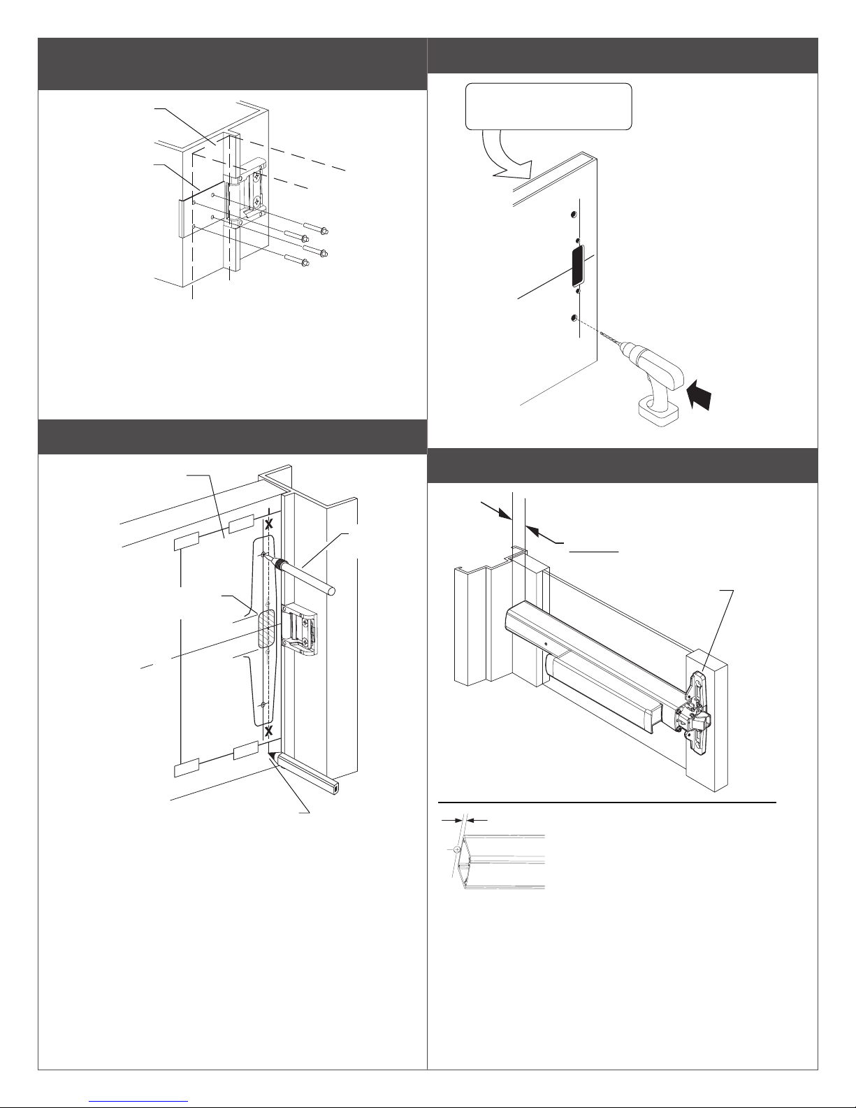
4 If using a 1439 strike, install wear strip. If not, go to
step 5.
Door
side
Wear
strip
A. Center wear strip on strike as shown.
6 Prepare lock side of door for device and trim.
See trim instructions for
pull side door preparation.
X
See template for drill and
cut-out information
B. Mark and drill 1/8” dia. holes (4 places).
C. Install wear strip with flat head drive
rivets (4 places) from 1439 strike package.
5 Tape template to door and mark door.
Paper Template
(pages 11 and 12)
Mark door
cut-out
C
L
Mark 4
holes
X
7 Measure to determine length to cut device.
1-3/16” minimum clearance
(with end cap removed)
dengila eciveD
gnitnuom htiw
seloh
Mark vertical line X-X for trim alignment
Note: Line X-X is a reference line on the paper template used for
trim and exit device alignment. Line X-X shown here should
correspond to line X-X in the trim installation instructions
”61/5
Note
If 5/8” diameter wire access hole
has been predrilled in door, cut
device 5/16” from center of hole.
4
 Loading...